

Overview
In this Getting Started tutorial, we will learn about the Raspberry Pi Pico, a brand new exciting Microcontroller board based on RP2040 Microcontroller from the Raspberry Pi Foundation. The Raspberry Pi Pico is a low-cost Arm-based microcontroller that we can program using C/C++ and MicroPython.
Over the years Raspberry Pi boards have become a must tool for students, hobbyists,s or Industrialists. But when it comes to cost, the Raspberry Pi Board is overtaken by Arduino, ESP32, STM32, or other AVR, ARM, PIC Microcontrollers. The Raspberry Pi computer costs around 35-40$ whereas the other microcontrollers barely cost 2-5$ only. This is the reason why Raspberry Pi Foundation released their low-cost powerful competitive Raspberry Pi Pico Board with RP2040, a Dual Core ARM Cortex-M0+ Microcontroller.
The tutorial covers the RP2040 Microcontroller, its features & specifications. We will also learn about the Raspberry Pi Pico Board, its layout, and specifications. The detailed guide of Raspberry Pi Pico Pins like ADC pins, I2C Pins, SPI Pins, UART, etc can help you to interface any sensors or module with this powerful board.
Since it’s a Raspberry Pi Pico getting started tutorial, so we will only program the device using Micropython. For that, you can either use Thonny IDE or you can also go with uPyCraft IDE. In some other tutorials, we will learn how to program Raspberry Pi Pico with C/C++. Even the Arduino IDE will support Raspberry Pie Pico in the future as it is in the development phase now. We will go through the basic Raspberry Pi Pico LED Blink Code & check the board functionality.
What is RP2040 Microcontroller?
Earlier all the Raspberry Pi boards like Raspberry Pi 3 or 4 or Raspberry Pi Zero featured Broadcom Processors like BCM2835, BCM2836, BCM2711 etc. The RP2040 chip was announced on 21st January 2021 and is the first processor designed by the Raspberry Pi Foundation.
The RP2040 is a 32-bit dual ARM Cortex-M0+ microcontroller integrated circuit released at the same time as part of the Raspberry Pi Pico board. The processor is a low-cost microcontroller and costs around US$4. The chip is 40nm silicon in a 7×7 mm QFN-56 package.
The RP2040 contains two ARM Cortex-M0+ cores clocked at 133 MHz together with 264 KB of RAM. The Program memory is external and supports up to 16 MB. The device has everything you expect from a modern microcontroller like UARTS, SPI, and I2C ports, and there are timers, PWM, DMA, and a 12-bit analog-to-digital converter (ADC).
Meaning of RP2040
The name RP2040 has a very interesting meaning explained below.
1. RP means: Raspberry Pi
2. Number 2 means: Processor Cores as it is a dual-core microcontroller. So, the value is 2.
3. Number 0 means: Type of Processor Core as it is ARM Cortex-M0+. So, the value is 0.
4. Number 4 means: Represents On-chip RAM. RP2040 has 264 KB of RAM. The formula to get 4 value is: floor (log2 (ram / 16k)). So, the value is 4.
5. Number 0 means: Represents On-chip Flash. As there is no on-chip flash, the value is 0.
RP2040 Key features:
- 133MHz dual ARM Cortex-M0+ cores
- 264kB SRAM in six independent banks
- Support for up to 16MB of off-chip Flash memory via dedicated QSPI bus
- DMA controller
- Fully-connected AHB crossbar
- Interpolator and integer divider peripherals
- On-chip programmable LDO(Low-dropout_regulator) to generate core voltage
- 2 on-chip PLLs to generate USB and core clocks
- 30 GPIO pins, 4 of which can be used as analog inputs
Introduction to Raspberry Pi Pico
The Raspberry Pi Pico is the first microcontroller board based on the RP2040. It looks a lot like other microcontroller boards with the MCU in the center, a micro-USB connector on one end, and a row of contacts along each side. A 3-pin debug connector is available at the other end of the board.

The Raspberry Pi Pico measures 51 by 21 mm, which is the exact same size as an ESP32 Pico Kit & slightly larger than an Arduino Nano or Micro. The Pico comes with 2 MB of QSPI Flash memory and 25 of the 30 GPIO pins of the RP2040 have been brought out on the extension connectors. The board is breadboard friendly and fits perfectly on breadboard.

Features of Raspberry Pi Pico
Following are the features of Raspberry Pi Pico Board.
1. Based on RP2040 Microcontroller
2. 2 MB of SPI Flash Memory
3. Type B Micro-USB port for power & programming
4. 40 DIP style IO Pins
5. 3-pin ARM Serial Wire Debug (SWD) interface
6. 12 MHz Crystal oscillator
7. Boot Selection Button
8. Programmable LED connected to GPIO 25
9. 3.3V Fixed Output Buck-Boost SMPS Converter
Raspberry Pi Pico Pinout
This is a top view of the pinouts on the Raspberry Pi Pico. The pin labels are on the bottom of the board.

There are 40-pin on the Raspberry Pi Pico. Out of those 40 pins, 26 pins are Input-Output (IO Pins). All those 14 pins are analog, digital, and other Serial Pins. There are 14 power and system-related pins. The remaining 3 more pins are used for SWD Debugging.
There are two I2C peripherals available, I2C0 and I2C1. Similarly, there are two SPI peripherals, SPI0 and SPI1The number of UART Pins are also two, UART0 and UART1. You can assign any of these to the pins on which they are available.
Before you start using Raspberry Pi Pico, you have to solder 40 pin male headers, 20 on each side of the board.

Programming Raspberry Pi Pico
The Pi Pico can be programmed using C/C++ or Python, among other languages. Pico is adaptable to a vast range of applications and skill levels, and getting started is as easy as dragging and dropping a file. If you are working with C, then it is recommended to use a Linux based system like a Raspberry Pi Computer as it is easy to download the SDK and write C Programs in Linux.
But I will recommend using MicroPython to program the Raspberry Pi Pico Board. MicroPython is a Python Language Interpreter that is developed for Microcontrollers and embedded systems. The Syntax for MicroPython is very similar to Python. So, if you worked with Python, then working with MicroPython will be very easy.
To program the Raspberry Pi Pico using Micropython, you can either use:
1. Thonny IDE
2. uPyCraft IDE
But before getting started with Raspberry Pi Pico, you have to install MicroPython on Raspberry Pi Pico Board.
Installing MicroPython on Raspberry Pi Pico
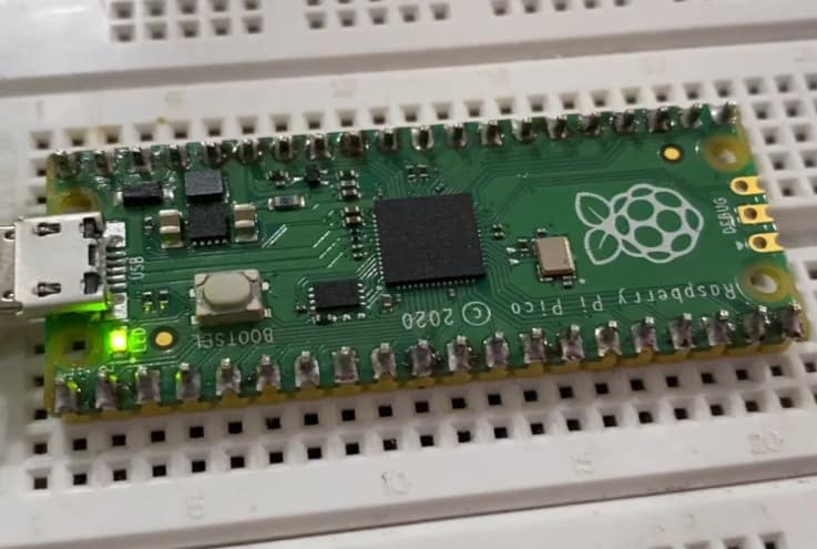
Push and hold the BOOTSEL button on the Pico, & then immediately connect the Pico Board to your computer using a micro USB cable. Release BOOTSEL once the drive RPI-RP2 appears on your computer.

Open the RPI-RP2 drive that appears in the Drives tab.

Visit the Raspberry Pi Pico Official Documentation page from here: Raspberry Pi Documentation.

Download the MicroPython UF2 file from the MicroPython tab.

Drag and drop the UF2 file onto the RPI-RP2 drive. The Raspberry Pi Pico will reboot and will now run MicroPython.

Getting Started with Raspberry Pi Pico using MicroPython on Thonny IDE
- Now let us get started with Raspberry Pi Pico using MicroPython on Thonny IDE. First you have to download Thonny from the https://thonny.org/

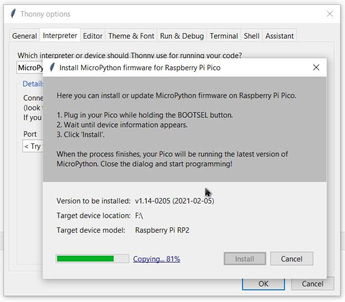
- Connect the Raspberry Pi Pico to your computer. Then from Thonny go to Tools > Options and click on the Interpreter tab. From the interpreter dropdown list, select MicroPython (Raspberry Pi Pico). The port dropdown menu can be left to automatically detect the Pico. Click Ok to close.

- When you plugin the pico Board, a firmware installation tab will appear for raspberry pi pico. Click on Install & some files will be downloaded.
- After successful installation, the MicroPython version and Raspberry board will appear in the Python Shell. To test we can write a quick print function to say “Hello World”. Press Enter to run the code. You will get Hello World as a response.

Writing a blink program for the onboard LED of pico
The on-board LED on the Raspberry Pi Pico is connected to GPIO25. Copy the following code and paste it on the editor window.
|
1 2 3 4 5 6 7 8 |
from machine import Pin import utime led = Pin(25, Pin.OUT) led.low() while True: led.toggle() print("Toggle") utime.sleep(1) |
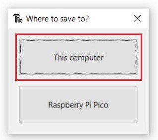
Save the program on the computer and give a unique name like blink.py
- The program will run and you can see the LED toggling in the board

Now unplug the USB of Raspberry Pi Pico and plug back in again. You will see the LED isn’t blinking. This is because the program is saved in the computer, not in the Raspberry Pi Pico Board.
To make the system work even after plugging and unplugging the USB cable, you need to save the program to the Pico Board. To do that open a new tab and paste the same program and click on save. This time save it on the Pico Board.
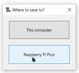
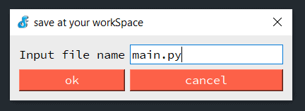
While saving give it a name main.py as shown in the image below.

This time the LED will blink even after plugging and removing the power cable. This is because the program is saved in the Pi Board.
Writing a blink program for the external LED
Now let us write a Raspberry Pi Pico LED Blink code to Blink an external LED connected to Raspberry Pi Pico GPIO Pin28. The schematic is given below. Connect an LED to GPIO28 via 330ohm resistor.

Copy the following code and upload it to the Pico Board.
|
1 2 3 4 5 6 7 8 |
from machine import Pin import utime led = Pin(28, Pin.OUT) led.low() while True: led.toggle() print("Toggle") utime.sleep(1) |
As soon as the code runs, the LED will start blinking after every interval of 1 second.

Writing a program to blink both on-board & external LED
Now let us write a Raspberry Pi Pico Code to blink both the on-board and external LED. The code is very simple. Copy the following code and run.
|
1 2 3 4 5 6 7 8 9 10 11 |
from machine import Pin import utime led1 = Pin(25, Pin.OUT) led2 = Pin(28, Pin.OUT) led1.low() led2.low() while True: led1.toggle() led2.toggle() print("Toggle") utime.sleep(1) |
Once the code run, the both LED will blink, i.e the on-board LED & also the external LED.

Getting Started with Raspberry Pi Pico using MicroPython on uPyCraft IDE
You can also program the Rapsberry Pi Pico RP2040 Microcontroller using uPyCraft IDE. The uPyCraft IDE is similar to Thonny IDE. We have already explained in detail about the uPyCraft IDE on ESP32 using Micropython previously. You can check it.
First download uPyCraft IDE from the following link: https://github.com/DFRobot/uPyCraft. Now open the uPyCraft IDE.

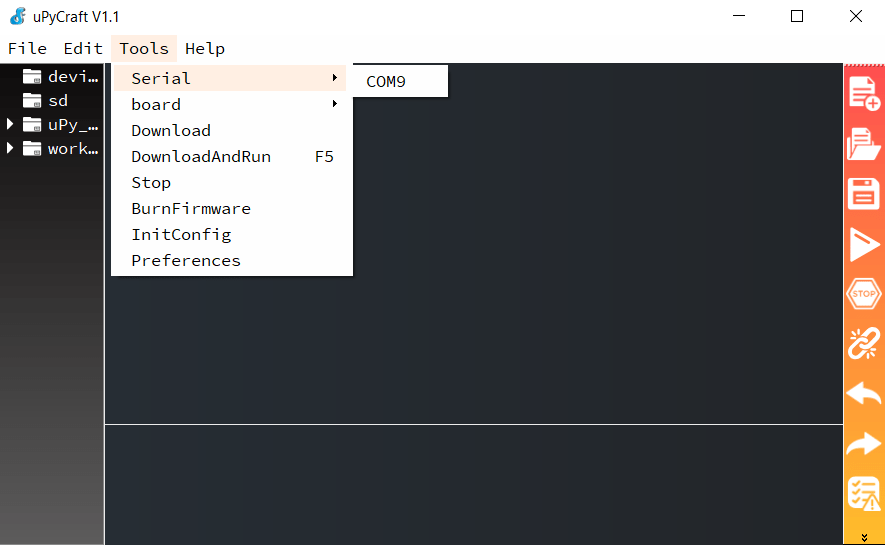
Click on Tools & from the Tools Menu select the COM Port.
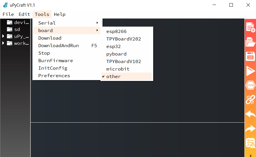
From the tools, select Board and then select others.
Now copy the following Raspberry Pi Pico LED Blink Code and paste it on the New Tab in uPyCraft IDE.

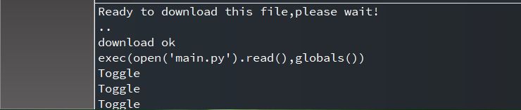
Save the file by the name main.py.
Then click on Download & Run Button from the right side. Once downloaded the LED will start blinking. You will be able to see toggle appearing on Shell Window.
You can test the rest of the above codes with uPyCraft IDE. The code will work with any IDE.
Related Raspberry Pi Pico Projects & Tutorials
You can follow the follow following Raspberry Pi Pico tutorials & projects.
1. Raspberry Pi Pico I2C Tutorial
2. Raspberry Pi Pico ADC Tutorial
3. Raspberry Pi Pico OLED Display Tutorial
4. Raspberry Pi Pico Internal Temperature Sensor
5. Raspberry Pi Pico DHT11 Sensor Tutorial
6. Raspberry Pi Pico 16X2 LCD Tutorial
Video Tutorial & Guide

For students, beginners and makers who want to learn Raspberry Pi Pico & MicroPython, you can buy the Raspberry Pi Pico Starter Kit and do almost 10 projects.


3 Comments
how do I use a sh1106 screen with a pi Pico I cant find any projects with that screen .
Any one prepared to set up my Pico for auto watering of a small green house. I have a pump, Pico 2 w sensors, solar panel, ATD converter, solenoid x2
Retired and hoping to play with controllers, RPi etc , inside my hobby which is gardening NOT COMMERCIAL
George,
Go to chat.openai.com. Create an account. Tell it in the subsequent chat window something like: Write micro python code for a raspberry pi pico that (here you tell it in English what you want your pico to do like read your water sensor and turn on a valve, etc.). Keep playing with your English instructions till the code does what you want.