

Overview
In this tutorial, we will be interfacing the BMI160 Accelerometer & Gyroscope with the Raspberry Pi Pico using MicroPython. The BMI160 is a small, low-power, low-noise 16-bit inertial measurement unit that integrates a 3-axis accelerometer and a 3-axis gyroscope. It provides precise motion sensing for applications like augmented reality, fitness tracking, and indoor navigation.
This tutorial provides detailed information about the BMI160 Accelerometer Gyroscope Module, including its specifications and technical details. First, we will interface the BMI160 with a Raspberry Pi Pico and then write a MicroPython code to convert the accelerometer raw values to Acceleration and Tilt Angles (Pitch & Roll).
Bill of Materials
We will need the following components for this tutorial. You can purchase all the components from the given links.
| S.N. | Components Name | Quantity | Purchase Link |
|---|---|---|---|
| 1 | Raspberry Pi Pico | 1 | Amazon | AliExpress |
| 2 | BMI160 Accelerometer Gyroscope | 1 | Amazon | AliExpress |
| 3 | Connecting Wires | 10 | Amazon | AliExpress |
| 4 | Breadboard | 1 | Amazon | AliExpress |
BMI160 3 Axis Accelerometer & Gyroscope
The BMI160 is a high-performance, small, and ultra-low-power 16-bit Inertial Measurement Unit (IMU) that combines a 3-axis accelerometer and a 3-axis gyroscope in a single package.
It is designed to deliver accurate and reliable motion sensing for a wide range of applications, such as augmented reality, indoor navigation, wearable devices, and gaming. The sensor offers advanced features like motion detection, step counting, and gesture recognition, making it versatile for modern technology needs.
The BMI160 supports both I2C and SPI interfaces for communication, making it compatible with a variety of microcontrollers and processors. It has a compact footprint of just 2.5 x 3.0 x 0.8 mm³, which is smaller than many competing IMUs, such as the MPU6050, and is well-suited for space-constrained devices like wearables. Refer to Bosch BMI160 Datasheet for more information.
Technical Specifications of BMI160
- Operating Voltage: 1.71 – 3.6 V (Breakout Board operates between 3.2V~6V)
- Power Consumption:
- Gyroscope: 900 µA (full operation)
- Gyroscope + Accelerometer: 950 µA (full operation)
- Accelerometer: 180 µA (full operation)
- Suspend Mode: 3 µA
- Motion Detection: 200 µA
- Acceleration Range: ±2g/±4g/±8g/±16g
- Gyroscopes Range: ±125°/s,±250°/s,±500°/s,±1000°/s,±2000°/s
- Acceleration Zero-g Offset: ±40mg
- Gyroscopes Zero-g Offset: ±10°/s
- Interfaces:
- Primary: I2C or SPI
- Secondary: High-speed SPI for optical image stabilization
- Noise Density:
- Accelerometer: 180 µg/√Hz
- Gyroscope: 0.008 °/s/√Hz
- Programmable Frequency: 25/32Hz~1600Hz
- 6D Detection and Location
- 16-bit Data Output
- Shock Resistance: 1000gx 200us
- 2 Independent Programmable Interrupt Generators
- In-built 1024 Byte FIFO
Applications of BMI160
- Augmented Reality: Tracks motion for virtual environments.
- Indoor Navigation: Supports step counting and positioning.
- Mobile Devices: For smartphones and smartwatches.
- Wearables: Powers fitness and health devices.
- Gaming: Tracks motion in controllers.
- Cameras: Stabilizes images.
- Drones & Toys: Enables motion sensing.
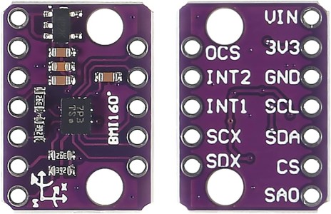
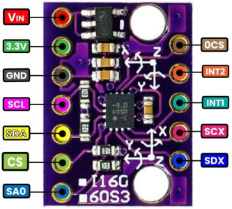
Pinout of BMI160
| Pin | Name | Description |
|---|---|---|
| VIN | VIN | Power input pin. Accepts 3.3V to 5V and steps it down for the BMI160 using an onboard regulator. |
| 3.3V | 3.3V | Regulated 3.3V output pin. |
| GND | GND | Ground pin. Connect to the ground of your system. |
| OCS | OCS | Optional Chip Select for secondary SPI interface (used in optical image stabilization). |
| INT1 | INT1 | Interrupt pin 1. Used for motion events or data-ready notifications. |
| INT2 | INT2 | Interrupt pin 2. An additional interrupt pin for more advanced use cases. |
| SCL/SCX | SCL or SCX | I2C clock line when using I2C communication. Acts as SPI clock (SCX) in SPI mode. |
| SDA/SDX | SDA or SDX | I2C data line when using I2C communication. Acts as SPI data (SDX) in SPI mode. |
| CS | CS | Chip Select pin for SPI communication. Used to select the BMI160 during SPI transactions. |
| SA0 | SA0 | I2C address selection pin. Connect to GND for address 0x68 or to 3.3V for 0x69. |
Interfacing BMI160 with Raspberry Pi Pico
Let us interface the BMI160 Gyroscope Accelerometer module with Raspberry Pi Pico Board. We can either use the module in SPI Mode or in I2C Mode. For this tutorial, we are using the I2C Mode as it just requires 2 wires.
Here is an interfacing circuit diagram for the connection between BMI160 and Raspberry Pi Pico Board.

| BMI160 Pin | Raspberry Pi Pico | Description |
|---|---|---|
| 3.3V | 3.3V | Power input for the BMI160. |
| GND | GND | Ground connection. |
| SCL | GP1 | I2C Clock line. |
| SDA | GP0 | I2C Data line. |
| SA0 | GND | Sets I2C address to 0x68. |
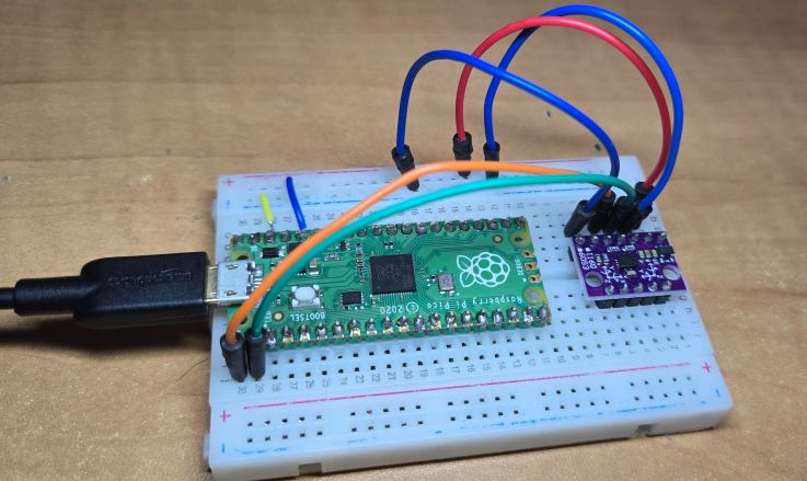
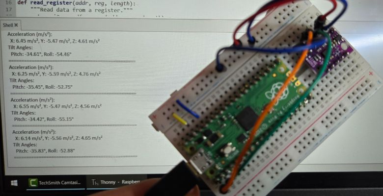
You can use a breadboard to connect the BMI160 with Raspberry Pi Pico as per the circuit diagram.
MicroPython Code
After hardware connection is done, now lets write an MicroPython Code to read the Raw Acceleration and Gyroscope Data from BMI160 Module & Raspberry Pi Pico. We will use some mathematical equations to convert the raw values into acceleration and gyroscopic value.
Raw values are converted to 𝑚/𝑠^2 using the formula:

Sensitivity for ±2g is 16384 LSB/g. Adjust if you use a different range.
The angle of rotation around the X-axis is called as Pitch which is calculated using the following formula:

The angle of rotation around the Y-axis is called as Roll which is calculated using the following formula:

This code uses a Raspberry Pi Pico to interface with the BMI160 sensor via I2C. It measures acceleration in m/s² and calculates tilt angles (pitch and roll). Auto-calibration is performed to remove offsets. Accurate readings are printed continuously.
|
1 2 3 4 5 6 7 8 9 10 11 12 13 14 15 16 17 18 19 20 21 22 23 24 25 26 27 28 29 30 31 32 33 34 35 36 37 38 39 40 41 42 43 44 45 46 47 48 49 50 51 52 53 54 55 56 57 58 59 60 61 62 63 64 65 66 67 68 69 70 71 72 73 74 75 76 77 78 79 80 81 82 83 84 85 86 87 88 89 90 91 92 93 94 95 96 97 98 99 100 101 102 103 |
from machine import I2C, Pin import math import time # Constants BMI160_I2C_ADDR = 0x68 ACCEL_SENSITIVITY = 16384.0 # ±2g sensitivity for the accelerometer in LSB/g # Initialize I2C with specified pins i2c = I2C(0, scl=Pin(1), sda=Pin(0), freq=400000) def write_register(addr, reg, data): """Write data to a register.""" i2c.writeto_mem(addr, reg, bytes([data])) def read_register(addr, reg, length): """Read data from a register.""" return i2c.readfrom_mem(addr, reg, length) def initialize_bmi160(): """Initialize the BMI160 sensor.""" # Set accelerometer to normal mode write_register(BMI160_I2C_ADDR, 0x7E, 0x11) # ACC_NORMAL_MODE time.sleep(0.1) def read_raw_acceleration(): """Read raw acceleration data.""" data = read_register(BMI160_I2C_ADDR, 0x12, 6) # Read accel data ax_raw = int.from_bytes(data[0:2], 'little') - (1 << 16 if data[1] & 0x80 else 0) ay_raw = int.from_bytes(data[2:4], 'little') - (1 << 16 if data[3] & 0x80 else 0) az_raw = int.from_bytes(data[4:6], 'little') - (1 << 16 if data[5] & 0x80 else 0) return ax_raw, ay_raw, az_raw def auto_calibrate(): """Perform auto-calibration to remove noise or error.""" print("Starting auto-calibration...") num_samples = 100 ax_offset = 0 ay_offset = 0 az_offset = 0 for _ in range(num_samples): ax_raw, ay_raw, az_raw = read_raw_acceleration() ax_offset += ax_raw ay_offset += ay_raw az_offset += az_raw time.sleep(0.01) # Small delay between readings # Calculate average offsets ax_offset //= num_samples ay_offset //= num_samples az_offset //= num_samples # Assuming the sensor is stable, Z-axis should measure 1g (gravity) az_offset -= int(ACCEL_SENSITIVITY) print("Auto-calibration completed.") print("Offsets - X: {}, Y: {}, Z: {}".format(ax_offset, ay_offset, az_offset)) return ax_offset, ay_offset, az_offset def read_acceleration(ax_offset, ay_offset, az_offset): """Read raw acceleration data, apply offsets, and convert to m/s².""" ax_raw, ay_raw, az_raw = read_raw_acceleration() ax = ((ax_raw - ax_offset) / ACCEL_SENSITIVITY) * 9.81 # Convert to m/s² ay = ((ay_raw - ay_offset) / ACCEL_SENSITIVITY) * 9.81 # Convert to m/s² az = ((az_raw - az_offset) / ACCEL_SENSITIVITY) * 9.81 # Convert to m/s² return ax, ay, az def calculate_tilt_angles(ax, ay, az): """Calculate pitch and roll angles from acceleration.""" pitch = math.atan2(ay, math.sqrt(ax**2 + az**2)) * 180.0 / math.pi roll = math.atan2(-ax, az) * 180.0 / math.pi return pitch, roll # Initialize BMI160 initialize_bmi160() print("BMI160 Initialized") # Perform auto-calibration ax_offset, ay_offset, az_offset = auto_calibrate() while True: try: # Read acceleration values ax, ay, az = read_acceleration(ax_offset, ay_offset, az_offset) # Calculate tilt angles pitch, roll = calculate_tilt_angles(ax, ay, az) # Print acceleration values print("Acceleration (m/s²):") print(" X: {:.2f} m/s², Y: {:.2f} m/s², Z: {:.2f} m/s²".format(ax, ay, az)) # Print tilt angles print("Tilt Angles:") print(" Pitch: {:.2f}°, Roll: {:.2f}°".format(pitch, roll)) print("=" * 50) except OSError as e: print("I2C Error: ", e) time.sleep(0.1) |
Copy the above code in Thonny IDE editor window. Then run the code.
When the module is placed on a stable surface without any movements and vibrations, it gives following results.
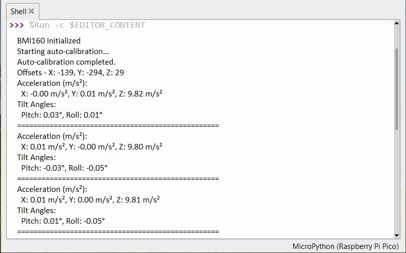
The acceleration in x and y axis is zero but in z axis it shows 9.81. This is due to the gravitational pull of the earth. Similarly pitch and roll angles are almost zero.
To observe the change in acceleration and tilt angles, shake or tremble the module. You will observe the massive change in acceleration and tilt angles readings.
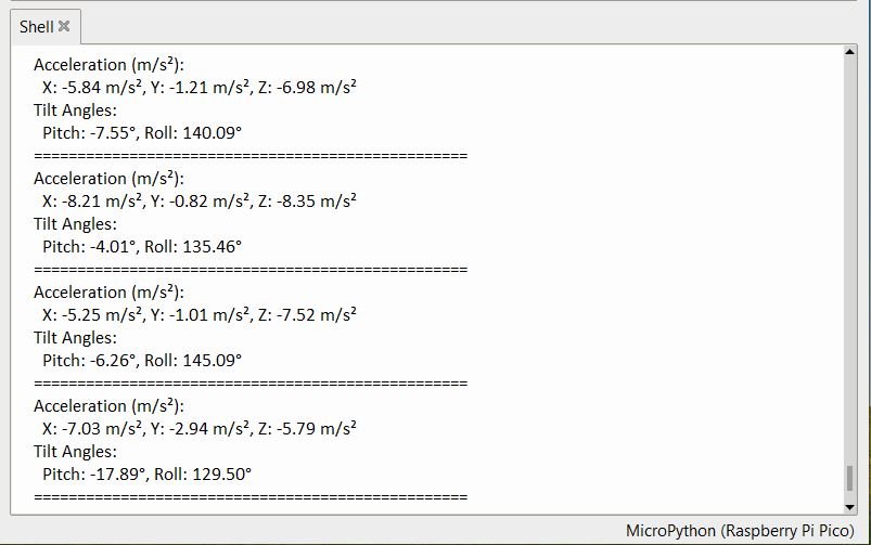
The tilt angle will only vary when the BMI160 is rotated in all 3 different axis.
This is how you can interface BMI160 Accelerometer Gyroscope Module with Raspberry Pi Pico using the MicroPython code.
Video Tutorial & Guide


