

Overview
In this project, we will learn how to make our own IoT Based Electricity Energy Meter using ESP32 & monitor data on the Blynk Application. Earlier we built IoT DC Energy Meter and GSM Prepaid Energy Meter. With the current technology, you need to go to the meter reading room and take down readings. Thus monitoring and keeping track records of your electricity consumption is a tedious task. To automate this, we can use the Internet of Things. The Internet of Things saves time and money by automating remote data collection. Smart Energy Meter has received quite a lot of acclaim across the globe in recent years. So, why not to build our own IoT Based Electricity Energy Meter?
We need to select the current sensor as well as the voltage sensor so that the current & voltage can be measured and thus we can know about the power consumption & total power consumed. The best current sensor available in the market is SCT-013. This is SCT-013 Non-Invasive AC Current Sensor Split Core Type Clamp Meter Sensor which can be used to measure AC current up to 100 amperes. Similarly, the best voltage sensor is the AC Voltage Sensor Module ZMPT101B. The ZMPT101B AC Voltage Sensor is the best where we need to measure the accurate AC voltage with a voltage transformer.
Using the SCT-013 Current Sensor & ZMPT101B Voltage Sensor, we can measure the all required parameters needed for Electricity Energy Meter. We will interface the SCT-013 Current Sensor & ZMPT101B Voltage Sensor with ESP32 Wifi Module & Send the data to Blynk Application. The Blynk Application Dashboard will display the Voltage, Current, Power & total unit consumed in kWh.
Bill of Materials
The list of components required for making IoT Based Electricity Energy Meter are given below. Most of the components can be ordered online from Amazon.
| S.N. | Components | Quantity | |
|---|---|---|---|
| 1 | ESP32 WiFi Module | 1 | Amazon | AliExpress |
| 2 | ZMPT101B AC Voltage Sensor Module | 1 | Amazon | AliExpress |
| 3 | SCT-013-030 Non-invasive AC Current Sensor | 1 | Amazon | AliExpress |
| 4 | 16x2 LCD Display | 1 | Amazon | AliExpress |
| 5 | Potentiometer 10K | 1 | Amazon | AliExpress |
| 6 | Resistor 10K | 2 | Amazon | AliExpress |
| 7 | Resistor 100ohm | 1 | Amazon | AliExpress |
| 8 | Capacitor 10uF | 1 | Amazon | AliExpress |
| 9 | Connecting Wires | 10 | Amazon | AliExpress |
| 10 | Breadboard | 1 | Amazon | AliExpress |
SCT-013 Current Sensor
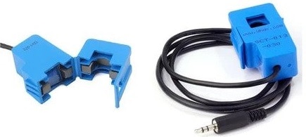
The SCT-013 is a Non-invasive AC Current Sensor Split Core Type Clamp Meter Sensor that can be used to measure AC current up to 100 amperes. Current transformers (CTs) are sensors are for measuring alternating current. They are particularly useful for measuring whole building electricity consumption. The SCT-013 current sensors can be clipped straight either to the live or neutral wire without having to do any high voltage electrical work.
![]()
Like any other transformer, a current transformer has a primary winding, a magnetic core, and a secondary winding. The secondary winding comprises many turns of fine wire housed within the casing of the transformer.
Specifications
1. Input Current: 0-30A AC
2. Output Signal: DC 0-1 V
3. Non-linearity: 2-3 %
4. Build-in sampling resistance (RL): 62 Ω
5. Turn Ratio: 1800:1
6. Resistance Grade: Grade B
7. Work Temperature: -25 °C~+70 °C
8. Dielectric Strength (between shell and output): 1000 V AC / 1 min 5 mA
ZMPT101B AC Single Phase Voltage Sensor

The ZMPT101B AC Single Phase voltage sensor module is based on a high precision ZMPT101B voltage Transformer used to measure the accurate AC voltage with a voltage transformer. This is an ideal choice to measure the AC voltage using Arduino or ESP32.
The Modules can measure voltage within 250V AC voltage & the corresponding analog output can be adjusted. The module is simple to use and comes with a multi-turn trim potentiometer for adjusting and calibrating the ADC output.
Specifications
1. Voltage up to 250 volts can be measured
2. Lightweight with on-board micro-precision voltage transformer
3. High precision on-board op-amp circuit
4. Operating temperature : 40ºC ~ + 70ºC
5. Supply voltage 5 volts to 30 volts
You can use ZMPT101B for AC Voltage Monitoring applications.
Circuit Diagram & Hardware Setup
Now let us see the circuit diagram of IoT Based Electricity Energy Meter using ESP32. The circuit has been designed using Fritzing software.

The connection diagram is simple. Both the Sensor, i.e. SCT-013 Current Sensor & ZMPT101B Voltage Sensor VCC is connected to Vin of ESP32 which is a 5V Supply. The GND pin of both the modules is connected to the GND of ESP32. The output analog pin of the ZMPT101B Voltage Sensor is connected to GPIO35 of ESP32. Similarly, the output analog pin of SCT-013 Current Sensor is connected to GPIO34 of ESP32. You need a two resistor of 10K & a single resistor of 100 ohms connected along with a 10uF Capacitor.
Apart from the circuit part, the AC wires where the current and voltage needs to measured are connected to the input AC Terminal of Voltage Sensor. Similarly, the current sensor clip doesn’t have any connection and a single live wire or neutral wire is inserted inside the clip part as shown in the above circuit.

The 16×2 LCD used in this project is optional. There is no need to connect the LCD as we will be monitoring the ESP32/SCT-013 ZMPT101B/ Energy Meter Data on Blynk Application. In case you want to connect the LCD, you need so many connections. Connect the pin numbers 4, 6, 11, 12, 13, 14 of LCD to ESP32 D13, D12, D14, D27, D26, D25 pins. Also connect the LCD 1, 5, 16 Pin to GND & 2, 15 Pin to 5V VCC. Use a 10K Potentiometer at Pin 3 of LCD to adjust the LCD Contrast.
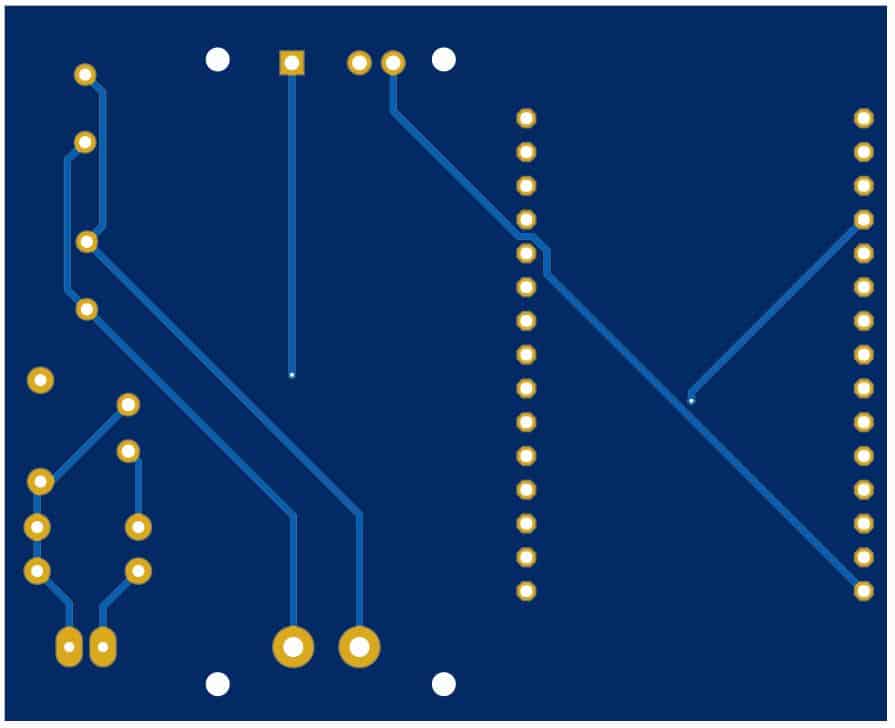
Project PCB Gerber File & PCB Ordering Online
If you don’t want to assemble the circuit on breadboard and you want PCB for the project, then here is the PCB for you. The PCB Board for the IoT Energy Meter is designed using EasyEDA online Circuit Schematics & PCB designing tool. The front side and back side of the PCB is given below.

The Gerber File for the PCB is given below. You can simply download the Gerber File and order the PCB from ALLPCB at 1$ only.
You can use this Gerber file to order high quality PCB for this project. To do that visit the ALLPCB official website by clicking here: https://www.allpcb.com/.

You can now upload the Gerber File by choosing the Quote Now option. From these options, you can choose the Material Type, Dimensions, Quantity, Thickness, Solder Mask Color and other required parameters.

After filling all details, select your country and shipping method. Finally you can place the order.
Setting Up Blynk Application
Blynk is an application that runs over Android and IOS devices to control any IoT based application using Smartphones. It allows you to create your Graphical user interface for IoT application. Here we will display the IoT Energy Meter Data on Blynk Application.
- So download and install the Blynk Application from Google Play Store. IOS users can download from the App Store. Once the installation is completed, open the app & sign-up using your Email id and Password.
- From the dashboard create a new project and select ESP32 & Wifi Connection.
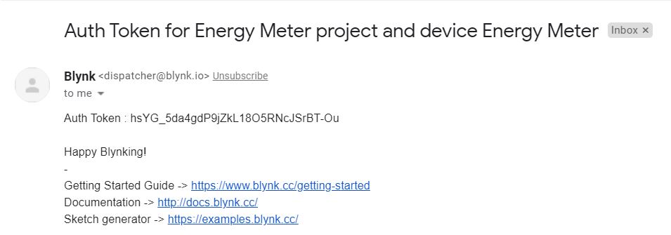
- Then drag & drop or add 4 widgets and assign the variable as per code and then email the authentication code.
- You will get the authentication code in the mail. Copy this authentication code. This will be used in your code.
Required Library Installation
1. EmonLib Library
The Emonlib Library is used for Electricity Energy Meter. EmonLib is a Continuous Monitoring of Electricity Energy repeats, every 5 or 10s, a sequence of voltage and current measurements. EemonLib continuously measures in the background the voltage and all the current input channels, calculates a true average quantity for each and then informs the sketch that the measurements are available and should be read and processed.
2. Blynk Library
Blynk is the most popular Internet of Things platform for connecting any hardware to the cloud, designing apps to control them, and managing your deployed products at scale. With Blynk Library you can connect over 400 hardware models including Arduino, ESP8266 & ESP32 to the Blynk Cloud.
Source Code/Program – IoT Electricity Energy Meter
After Adding the above libraries to the Arduino IDE, you can upload the IoT Electricity Energy Meter Code to ESP32 Board.
But before that please make changes to the WiFi SSID, Password & Blynk Authentication Token.
|
1 2 3 |
char auth[] = "605c2d780fd*******d7a31611"; char ssid[] = "*************************"; char pass[] = "************************"; |
The complete code is given below.
|
1 2 3 4 5 6 7 8 9 10 11 12 13 14 15 16 17 18 19 20 21 22 23 24 25 26 27 28 29 30 31 32 33 34 35 36 37 38 39 40 41 42 43 44 45 46 47 48 49 50 51 52 53 54 |
#define BLYNK_PRINT Serial #include "EmonLib.h" //https://github.com/openenergymonitor/EmonLib #include <WiFi.h> #include <WiFiClient.h> #include <BlynkSimpleEsp32.h> EnergyMonitor emon; #define vCalibration 106.8 #define currCalibration 0.52 BlynkTimer timer; char auth[] = "*********************"; char ssid[] = "*********************"; char pass[] = "*********************3"; float kWh = 0; unsigned long lastmillis = millis(); void myTimerEvent() { emon.calcVI(20, 2000); Serial.print("Vrms: "); Serial.print(emon.Vrms, 2); Serial.print("V"); Blynk.virtualWrite(V0, emon.Vrms); Serial.print("\tIrms: "); Serial.print(emon.Irms, 4); Serial.print("A"); Blynk.virtualWrite(V1, emon.Irms); Serial.print("\tPower: "); Serial.print(emon.apparentPower, 4); Serial.print("W"); Blynk.virtualWrite(V2, emon.apparentPower); Serial.print("\tkWh: "); kWh = kWh + emon.apparentPower*(millis()-lastmillis)/3600000000.0; Serial.print(kWh, 4); Serial.println("kWh"); lastmillis = millis(); Blynk.virtualWrite(V3, kWh); } void setup() { Serial.begin(9600); emon.voltage(35, vCalibration, 1.7); // Voltage: input pin, calibration, phase_shift emon.current(34, currCalibration); // Current: input pin, calibration. Blynk.begin(auth, ssid, pass); timer.setInterval(5000L, myTimerEvent); } void loop() { Blynk.run(); timer.run(); } |
Source Code/Program – IoT Electricity Energy Meter with LCD
|
1 2 3 4 5 6 7 8 9 10 11 12 13 14 15 16 17 18 19 20 21 22 23 24 25 26 27 28 29 30 31 32 33 34 35 36 37 38 39 40 41 42 43 44 45 46 47 48 49 50 51 52 53 54 55 56 57 58 59 60 61 62 63 64 65 66 67 68 69 70 71 72 73 74 75 76 77 78 79 80 81 82 83 84 85 86 87 88 89 90 91 92 93 94 95 96 97 |
#include <LiquidCrystal.h> LiquidCrystal lcd(13, 12, 14, 27, 26, 25); #define BLYNK_PRINT Serial #include "EmonLib.h" #include <WiFi.h> #include <WiFiClient.h> #include <BlynkSimpleEsp32.h> EnergyMonitor emon; #define vCalibration 83.3 #define currCalibration 0.50 BlynkTimer timer; char auth[] = "hsYG_5da4gdP9jZkL18O5RNcJSrBT-Ou"; char ssid[] = "Alexahome"; char pass[] = "loranthus"; float kWh = 0; unsigned long lastmillis = millis(); void myTimerEvent() { emon.calcVI(20, 2000); kWh = kWh + emon.apparentPower * (millis() - lastmillis) / 3600000000.0; yield(); Serial.print("Vrms: "); Serial.print(emon.Vrms, 2); Serial.print("V"); Serial.print("\tIrms: "); Serial.print(emon.Irms, 4); Serial.print("A"); Serial.print("\tPower: "); Serial.print(emon.apparentPower, 4); Serial.print("W"); Serial.print("\tkWh: "); Serial.print(kWh, 5); Serial.println("kWh"); lcd.clear(); lcd.setCursor(0, 0); lcd.print("Vrms:"); lcd.print(emon.Vrms, 2); lcd.print("V"); lcd.setCursor(0, 1); lcd.print("Irms:"); lcd.print(emon.Irms, 4); lcd.print("A"); delay(2500); lcd.clear(); lcd.setCursor(0, 0); lcd.print("Power:"); lcd.print(emon.apparentPower, 4); lcd.print("W"); lcd.setCursor(0, 1); lcd.print("kWh:"); lcd.print(kWh, 4); lcd.print("W"); delay(2500); lastmillis = millis(); Blynk.virtualWrite(V0, emon.Vrms); Blynk.virtualWrite(V1, emon.Irms); Blynk.virtualWrite(V2, emon.apparentPower); Blynk.virtualWrite(V3, kWh); } void setup() { Serial.begin(9600); Blynk.begin(auth, ssid, pass); lcd.begin(16, 2); emon.voltage(35, vCalibration, 1.7); // Voltage: input pin, calibration, phase_shift emon.current(34, currCalibration); // Current: input pin, calibration. timer.setInterval(5000L, myTimerEvent); lcd.setCursor(3, 0); lcd.print("IoT Energy"); lcd.setCursor(5, 1); lcd.print("Meter"); delay(3000); lcd.clear(); } void loop() { Blynk.run(); timer.run(); } |
Code Explanation
|
1 2 3 4 5 |
#define BLYNK_PRINT Serial #include "EmonLib.h" //https://github.com/openenergymonitor/EmonLib #include <WiFi.h> #include <WiFiClient.h> #include <BlynkSimpleEsp32.h> |
First, we include the necessary libraries for ESP32 Board. EmonLib handles the retrieval of data from both sensors as well as the calculation for the RMS and power values. BlynkSimpleEsp32 integrates the program to the Blynk Mobile app. The power can also be calculated using the AC Wattage Calculator.
|
1 2 3 4 |
EnergyMonitor emon; #define vCalibration 106.8 #define currCalibration 0.52 BlynkTimer timer; |
The EnergyMonitor object emon is created &calibration factors are defined. The Blynk timer object is then created to handle the sending of data to the Blynk mobile app.
|
1 2 3 |
char auth[] = "**********************************"; char ssid[] = "**********************************"; char pass[] = "**********************************"; |
Then we define the SSID & Password on our local wifi network & insert the authentication code from the Blynk.
|
1 2 |
float kWh = 0; unsigned long lastmillis = millis(); |
The millis & kWh values have to be initialized. The kWh starts at 0 and will slowly go up as time goes on.
|
1 2 |
emon.calcVI(20, 2000); kWh = kWh + emon.apparentPower * (millis() - lastmillis) / 3600000000.0; |
The values from the sensors are being retrieved & calculated. Using emon.calcVI(20, 2000), the real power, apparent power, power factor, Vrms, and Irms are being calculated.
|
1 2 3 4 |
Blynk.virtualWrite(V0, emon.Vrms); Blynk.virtualWrite(V1, emon.Irms); Blynk.virtualWrite(V2, emon.apparentPower); Blynk.virtualWrite(V3, kWh); |
We then use Blynk.virtualWrite to send the data to Blynk based on the virtual pins set.
|
1 2 3 4 5 |
Serial.begin(9600); emon.voltage(35, vCalibration, 1.7); // Voltage: input pin, calibration, phase_shift emon.current(34, currCalibration); // Current: input pin, calibration. Blynk.begin(auth, ssid, pass); timer.setInterval(5000L, myTimerEvent); |
Under the setup function we initialized the Serial baud rate and set the current and voltage sensor analog pin as GPIO34 & GPIO35. Then we set the timer to 5000L for an update time of 5 seconds
|
1 2 |
Blynk.run(); timer.run(); |
Inside the loop fucntion we are running the timer and Blynk
Testing: IoT Based Electricity Energy Meter using ESP32 & Blynk
The ESP32 Board will try connecting to the wifi Network using the given SSID & Password. The LCD Display will light up with the following message Initially.

When no load is connected or when the load is powered off the Current and Voltage parameters should be almost 0. If it shows some other value, then you need to modify the following calibration factor in the code.
|
1 2 |
#define vCalibration 106.8 #define currCalibration 0.52 |

Now when the load is connected, the LCD Display will display the Voltage and Current value on LCD Screen along with Power Consumption and total kWh units.


The energy meter data is uploaded to Blynk Application after the interval of every 5 seconds. The data can be observed on Serial Monitor as well as Blynk Application.


Thus, you can use this IoT Based Electricity Energy Meter to monitor the electricity consumption of your house.
Video Tutorial & Guide

UPDATE: The Blynk App got updated to the latest version, i.e Blynk 2.0. Therefore we have made IoT Smart Energy Meter using the new Blynk 2.0 App. You can follow the link below to start doing the project with new Blynk App with some more additional features.
Incase, you want more accurate results then you can use PZEM-004T AC Energy Meter module which can be interfaced with Arduino and ESP32 Microcontroller.


28 Comments
How can I get a software simulation for this
How can i do the node red instead blynk? Can you please help me and give the code for the node and mqtt
How can I do Mqtt node red instead of blynk? Can you please help me with the code?
Could this apply at 3 phase distribution board? And how to do that?
I need simulation file
Wonderfully detailed write-up. I’m building one myself right now. Everything in the explanation is very detailed except for “Use a 10K Potentiometer at Pin 3 of LCD to adjust the LCD Contrast.”. Last I looked, a potentiometer has 3 connections. Am I to assume one side of the pot to V+, other side to GND, and the middle connection to pin 3 of the LCD?
hello can i know which ESP32 board do we need to select?
Esp32 Dev Module
Source Code/Program with LCD not working LCD not displaying anything. can you please check
I am also facing the same problem, can any guide me? please
Admin I have made this project but nothing is displayed on my LCD also the Blynk app on laptop does connect to the WiFi.
can i get the simulation file of this project
can u please send the simulation file
Hello,
Why don’t you answer the rest of the questions?
I imagine that you publish the projects to have an audience and at the same time monetize.
hello i really need your help in this project urgently the project is awesome but just want to know something about lcd and breadboard plz help me
my whatsapp no +923401352413 plz help me am stuck at a point
come bro it will work i have spent two days on it and finally made it
there are some things you have to do
if anyone want this with working whatsapp me there is some changing needed in it
+923401352413 whatsapp number.
hello bro can i get circuit diagram with LED and potentiometer included.???
what to do for the supply…how do we supply the voltage and the current to the prototype
brother in my project the current sensor is not working can u help me
how can i add power factor
how to connect a relay
Hello. Thanks for this wonderful tutorial. I just want to ask that I am using firebase database instead of Blynk Application. Can you please tell me the code for firebase? The controller is same esp32. Thanks
If I want to use only the current sensor (not voltage), how does this affects the circuit?
Thanks for the tutorial, just querios how you calculated the calibration factors.
The information you need is on the OpenEnergyMonitor website under ‘guides’. This project is based on the work done by those people who are the creators of the emon library. To get accurate results one should use the ZMPT101B transformer alone not the module.
This project uses the ESP32 and the ADC is not very accurate, it also uses Blynk. Neither of those is covered on the OEM site.
Nice one 👍.
I trying to built something close to that but with 1306 LCD display. The system is able to monitor as well as switch mains contactor when voltage is high or overcurrent but code not coming through. Can you help me.
I Need your help.I upload code ESP 32 S but LCD did not work.However ESP does not connect Wifi.I tried diffrent simple project for example led project but it does not again.Probably ESP does not give out.
Is it possible this project with esp8266 – 01 ??
Not possible