

Overview
In this project, we will make a Smart Arduino Based AC Voltage Protection & Monitoring System with Under & Over Voltage Protection features. We can use a ZMPT101B voltage sensor to measure the current Voltage status and display it on LCD Display.
Nowadays there are a lot of AC Mains voltage fluctuations due to interruption of heavy load, thunder & lightning, and switching impulses. This can easily damage the electronics/electrical parts and sometimes lead to fire accidents. Voltage irregularities are the major issues in industries that often damage sensitive electronic equipment. In most cases, MCB is used as a protection system but it would be better if we implement our own system which could be cheaper and more advanced. Moreover, the system should have user input for under-voltage and over-voltage protection.
Many devices are available in the market for AC Voltage Monitoring along with Under, Normal & Over Voltage Protection features. But they are expensive and can’t have user input. This project aims to sort out all those drawbacks and develop protection & monitoring for the electrical equipment from over and under AC voltages using Arduino as a controller at a low cost. So we can use the ZMPT101B voltage sensor & Arduino to measure AC Voltage and based on under & over voltage detection, the Relay can turn off the entire system.
Bill of Materials
The following components are needed for this project. You can purchase the products from the given link.
| S.N. | Components | Quantity | Purchase Link |
|---|---|---|---|
| 1 | Arduino Nano | 1 | Amazon | AliExpress |
| 2 | 16X2 LCD Display | 1 | Amazon | AliExpress |
| 3. | ZMPT101B Voltage Sensor | 1 | Amazon | AliExpress |
| 4 | 5V Relay Module | 1 | Amazon | AliExpress |
| 5 | BC547 Transistor | 1 | Amazon | AliExpress |
| 6 | 1N4007 Diode | 1 | Amazon | AliExpress |
| 7 | Resistor 10K | 1 | Amazon | AliExpress |
| 8 | Resistor 1K | 1 | Amazon | AliExpress |
| 9 | Resistor 220-ohm | 1 | Amazon | AliExpress |
| 10 | LED 5mm (Multicolor) | 3 | Amazon | AliExpress |
What is Over Voltage & Under Voltage?
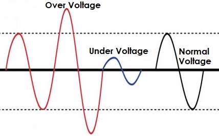
Overvoltages are the voltages that exceed the normal or rated values which cause insulation damage to electrical appliances leading to short circuits. To be more precise, it’s when a supply voltage of 10 percent and above the rated voltage occurs. The conditions may be hazardous. Depending on its duration, the overvoltage event can be transient—a voltage spike—or permanent, leading to a power surge.
Similarly, Undervoltage happens when the average voltage of equipment falls below the rated voltage amount. Frequent Undervoltage can result in a degradation in equipment performance and reliability.
Block Diagram: Arduino Over & Under AC Voltage Monitoring
Here is a simple block diagram of an AC Under Voltage Over Voltage Monitoring & Protection System with an Arduino Microcontroller.

In Asia and most parts of the world, the usual AC supply voltage is between 220-240V. There is a +2% tolerance for Voltage fluctuations. In case there is an increase above the tolerance voltage over voltage is detected. We have also set the under voltage as 190V in this circuit. And test with variations in under and over voltage, we have used 220V Fan AC Dimmer. You can make your own AC Dimmer by referring to our previous post.
In the above block diagram, 200V AC Mains is supplied directly to the ZMPT101B Voltage Sensor. In this project, the input voltage is varied using the Fan AC Dimmer instead of a direct 220V Power Supply. The output of the ZMPT101B is an Analog voltage that is below 5V and can be fed easily to the Arduino Analog pin. The Arduino Nano Board and Relay are powered via a 5V Power supply or a 5V DC Adapter. A Load can be connected across the output of the Relay.
We have used a 16×2 LCD Display for displaying the Voltage Value and also the under, normal and over-voltage conditions. Whenever the voltage goes beyond 220V, the over-voltage condition is achieved and Relay disconnects all the electrical appliances. The LCD will display overvoltage message. Similarly, if the voltage lies between 220V-190V the Relay turns ON as Normal Voltage is displayed on the LCD. In case the voltage further drops below 190V, the under voltage condition is achieved. The Relay will shut down the system and the LCD displays the Under Voltage message.
Tripping Time Calculation
The tripping time is to be calculated using the formula:
t = Time Multiplier
V = Voltage at A0
Vs = Source Voltage
Circuit Diagram: Arduino Over & Under AC Voltage Monitoring
Using the block diagram from above, we can make a simple circuit diagram using Arduino and some active passive electronic components.

Connect the 16×2 LCD Pin 4, 6, 11, 12, 13, and 14 to Arduino D3, D4, D5, D6, D7, and D8 Pin. Use a 10K Potentiometer at Pin 3 of LCD to adjust LCD Contrast. Supply 5V to LCD Pin 2 & 15. Connect LCD Pin 1, 5 & 16 to GND of Arduino.
Connect the Green and Yellow LED to digital pins D11 and D12 of Arduino. The LED1 is for Power indication. In order to control the Relay, we are using a BC547 transistor as a Switch. The diode 1N4007 which is across the Relay is serving as reverse voltage protection. You can connect multiple loads across the output of Relay. The load may be the AC Bulbs or any home appliances operating at 220V.

The ZMPT101B is an analog sensor. Therefore connect the analog pin of the sensor to Arduino A0 Pin. You can power the ZMPT101B, Relay Module using the 5V Pin of Arduino. The ZMPT101B accepts the input AC Voltage of 220V or over in our case. To test the Arduino Over & Under AC Voltage Monitoring Protection Circuit, AC Fan Dimmer is the best option.

Project PCB Gerber File & PCB Ordering Online
If you don’t want to assemble the circuit on a zero PCB and you want PCB for the project, then here is the PCB for you. I used EasyEDA to design the PCB. The PCB Board for AC Voltage Monitoring System looks something like below.

The Gerber File for the PCB is given below. You can simply download the Gerber File and order the PCB from ALLPCB at 1$ only.
You can use this Gerber file to order high quality PCB for this project. To do that visit the ALLPCB official website by clicking here: https://www.allpcb.com/.

You can now upload the Gerber File by choosing the Quote Now option. From these options, you can choose the Material Type, Dimensions, Quantity, Thickness, Solder Mask Color and other required parameters.

After filling all details, select your country and shipping method. Finally you can place the order.
You can assemble the components on the PCB Board.

ZMPT101B Voltage Sensor Calibration
Initially the ZMPT101B Voltage Sensor requires calibration as it doesn’t come pre-calibrated. First upload the following code to the Arduino Board.
|
1 2 3 4 5 6 7 8 9 10 |
void setup() { Serial.begin(9600); } void loop() { Serial.println(analogRead(A0)); delay(100); } |
After uploading the code, open the Serial Plotter. If the Serial Plotter doesn’t show the sine wave, then rotate the potentiometer to calibrate the sensor. Once it shows a proper sine wave, you can assume it as a proper calibration.

Source Code/Program
The following is the code for Over and Under AC Voltage Protection system using Arduino. Copy the code and paste it on the Arduino editor. The select the Arduino Nano Board from Board Manager and also the right COM port. Then you can upload the code.
|
1 2 3 4 5 6 7 8 9 10 11 12 13 14 15 16 17 18 19 20 21 22 23 24 25 26 27 28 29 30 31 32 33 34 35 36 37 38 39 40 41 42 43 44 45 46 47 48 49 50 51 52 53 54 55 56 57 58 59 60 61 62 63 64 65 66 67 68 69 70 71 72 73 74 75 76 77 78 79 80 81 82 |
#include <Filters.h> #include <LiquidCrystal.h> const int rs = 3, en = 4, d4 = 5, d5 = 6, d6 =7, d7 = 8; LiquidCrystal lcd(rs, en, d4, d5, d6, d7); float testFrequency = 50; int Sensor = 0; int relay = 10; int yellow = 12; int green = 11; float intercept = 0.7; float slope = 0.04; float current_Volts; unsigned long printPeriod = 1000; unsigned long previousMillis = 0; void setup() { lcd.begin(16, 2); pinMode(relay, OUTPUT); pinMode(yellow, OUTPUT); pinMode(green, OUTPUT); lcd.print("Voltage:"); delay(1000); } void loop() { RunningStatistics inputStats; while ( true ) { Sensor = analogRead(A0); inputStats.input(Sensor); if ((unsigned long)(millis() - previousMillis) >= printPeriod) { previousMillis = millis(); current_Volts = intercept + slope * inputStats.sigma(); current_Volts = current_Volts * (40.3231); lcd.setCursor(9, 0); lcd.print(current_Volts); lcd.print("V"); } if ( (current_Volts > 0) && (current_Volts < 190) ) { lcd.setCursor(0, 1); lcd.print("Under Voltage"); digitalWrite(relay, LOW); digitalWrite(yellow, LOW); digitalWrite(green, HIGH); } if ( (current_Volts >= 190) && (current_Volts <= 220) ) { lcd.setCursor(0, 1); lcd.print("Normal Voltage"); digitalWrite(relay, HIGH); digitalWrite(yellow, LOW); digitalWrite(green, LOW); } if ( current_Volts > 220 ) { lcd.setCursor(0, 1); lcd.print("Over Voltage"); digitalWrite(relay, LOW); digitalWrite(yellow, HIGH); digitalWrite(green, LOW); } } } |
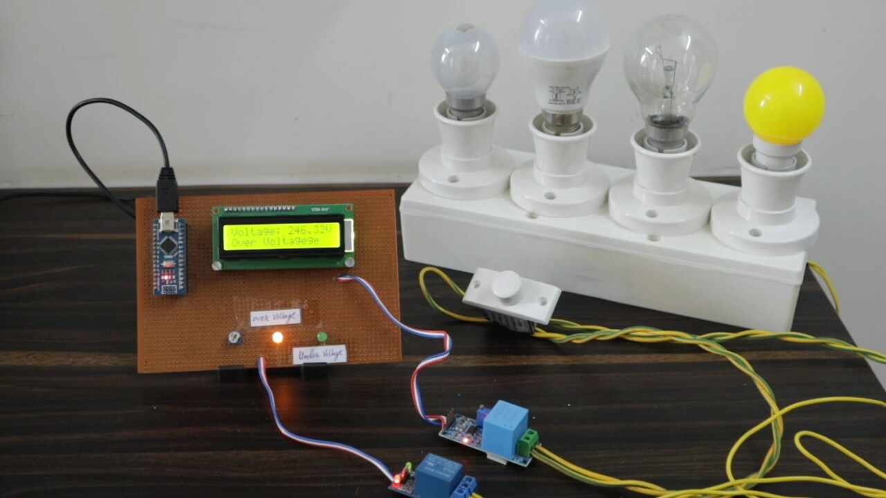
Testing: Under & Over Voltage Protection System
After uploading the code, the circuit is ready for testing. Under normal conditions, i.e when the voltage is between 190V to 220V, the load turns on and the system keeps working.

If the voltage goes beyond 220V, the load turns off and LCD Displays an Over Voltage message.
If the voltage goes below 190V, the load turns off and LCD Displays Under Voltage message.

This is how you can monitor the over-voltage and under voltage parameters using Arduino and ZMPT101B Voltage Sensor.
Video Tutorial & Guide


")


3 Comments
will i rum the code its give me error
1nz5vd5.5wql\sketch_mar27a\sketch_mar27a.ino:1:10: fatal error: Filters.h: No such file or directory
#include
^~~~~~~~~~~
compilation terminated.
exit status 1
Compilation error: Filters.h: No such file or directory
Error while running the program, how to fix because many lines are subjected to error?
Error while compiling in void loop : RunningStatistics not declared in this scope.
Please advise