

Overview
In this tutorial, we will learn how to interface INA219 DC Current Sensor Module with Arduino. Using the INA219 DC Current Sensor, we can measure the current, voltage and power. It can measure the voltage up to +26V and current upto 3.2A. If you want higher current upto 50A, you may use INA226 module.
INA219 is a shunt Current Sensor module introduced by the Texas instruments. It is a Zero-Drift, Bidirectional, Power Monitor module that monitors shunt voltage, Bus voltage, current, and power. For communication with microcontrollers, it employs an integrated interface that is compatible with both I2C and SMBus.
The INA219 can be used in various applications such as power management and overcurrent protection in servers, test equipment, battery chargers, and any system that requires a high-accuracy, low-cost method of monitoring power and current.
Bill of Materials
To interface INA219 DC Current Sensor Module with Arduino, we need following components. You can purchase all of them from the given links:
| S.N. | Components | Quantity | Purchase Link |
|---|---|---|---|
| 1 | Arduino Nano | 1 | Amazon | AliExpress | SunFounder |
| 2 | INA219 Current Sensor | 1 | Amazon | AliExpress |
| 3 | LED 5mm | 4 | Amazon | AliExpress | SunFounder |
| 4 | 330-ohm Resistor | 4 | Amazon | AliExpress| SunFounder |
| 5 | Jumper Wires | 10 | Amazon | AliExpress | SunFounder |
| 6 | Breadboard | 1 | Amazon | AliExpress | SunFounder |
INA219 DC Current Sensor Module

The INA219 is a high-side current shunt and power monitor IC developed by Texas Instruments. It operates on an I2C-compatible or SMBus-compatible interface which facilitates communication with microcontrollers. The key features of this IC are its ability to measure both shunt voltage drop and bus supply voltage, as well as its zero-drift architecture, which enables precise and consistent measurements.
Download INA219 Datasheet: INA219 Datasheet
INA219 Circuit & Schematic

The INA219 module is built with an INA219 chip, a few resistors, and a capacitor that helps reduce noise, or unwanted electrical signals.

Features & Specifications of INA219
- Operational Voltage (3 – 5.5 Volts): The INA219 operates between 3 to 5.5 volts, increasing its compatibility with various systems running at either 3.3V or 5V logic level. This feature enhances the module’s flexibility in diverse circuit designs.
- Bus Voltage Range (0 – 26 Volts): The INA219 can monitor power supplies within 0 to 26 volts range. This broad range makes the module applicable to low-voltage logic circuits and higher-voltage power supplies.
- Current Sensing Range (±3.2A with ±0.8mA resolution): The INA219 can monitor a current range of ±3.2A with a precise resolution of ±0.8mA. This capacity makes it suitable for various applications including power management, battery chargers, and DC motor control, enabling accurate tracking and control of power consumption.
- 0.1 ohm 1% 2W Current Sense Resistor: The module uses a 0.1-ohm shunt resistor with a 1% tolerance and 2W power rating for current sensing. The low resistance value minimizes power loss, while the 1% tolerance ensures measurement accuracy. The 2W power rating indicates its robustness, supporting current measurements up to ±3.2A.
Pinout of INA219
The INA219 sensor module typically has the following pins:

- VCC: This pin is used to supply the operating voltage to the INA219 module. It can handle an input voltage of 3.3V to 5.5V.
- GND: This is the Ground pin.
- SCL: This pin is used for the clock line of the I2C interface.
- SDA: This pin is used for the data line of the I2C interface.
- Vin-: This pin connects to the negative terminal of the voltage supply that you want to measure. This pin is also where the shunt resistor is placed and is used for current sensing.
- Vin+: This pin connects to the positive terminal of the voltage supply that you want to measure.
I2C Address
The INA219 uses the I2C protocol to communicate with microcontrollers, and each device on the I2C bus must have a unique address. The default I2C address for the INA219 is 0x40 (or 1000000 in binary).
The address can be changed if you want to use multiple INA219 sensors on the same I2C bus. The INA219 allows up to 16 different I2C addresses, ranging from 0x40 to 0x4F. This is achieved by configuring the states of the two address pins A0 and A1. On the INA219 module, these two pins, A0 and A1, are often found with solder pads or jumpers. By default, they are connected to the Ground (GND) which corresponds to the default address 0x40.
| A1 | A0 | Slave Address (Hex) |
|---|---|---|
| GND | GND | 0x40 |
| GND | 0x41 | |
| GND | SDA | 0x42 |
| GND | SCL | 0x43 |
| GND | 0x44 | |
| 0x45 | ||
| SDA | 0x46 | |
| SCL | 0x47 | |
| SDA | GND | 0x48 |
| SDA | 0x49 | |
| SDA | SDA | 0x4A |
| SDA | SCL | 0x4B |
| SCL | GND | 0x4C |
| SCL | 0x4D | |
| SCL | SDA | 0x4E |
| SCL | SCL | 0x4F |
You can change the I2C address by changing the connections of these pins to either GND, SDA, SCL, or leaving them floating (not connected). For instance, if you connect the A0 pin to SDA and A1 to GND, the address will be 0x48.
So, if you want to have multiple INA219 modules in the same system, you just need to set a unique address for each one by configuring the A0 and A1 pins accordingly. Remember, any time you change the I2C address, you must update the address in your microcontroller’s software so it knows where to find each INA219 on the I2C bus.
Register Address & Values Calculations
The INA219 has a set of internal registers that hold measurement data and control settings. They can be accessed via the I2C interface to configure the chip, initiate measurements, and read measurement results.
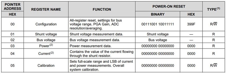
1. Configuration Register (Address = 00h): This register is used to control various aspects of the INA219, such as the bus voltage range, PGA gain, ADC resolution/averaging, operating mode, and more. It can be read or written to configure the INA219 as needed.
2. Shunt Voltage Register (Address = 01h): This register holds the raw measurement result for the shunt voltage. It can be read to obtain the shunt voltage measurement, and the value must be processed as per the datasheet’s guidance to get the actual voltage in volts.
Shunt voltage (in volts) is calculated by taking the raw reading from the Shunt Voltage Register and multiplying it by 10 µV. The formula is:
Bus voltage (in volts) is calculated by taking the raw reading from the Bus Voltage Register and multiplying it by 4 mV. The formula is:
Power (in watts) is calculated by taking the raw reading from the Power Register and multiplying it by the Power_LSB value (defined when the calibration register is set). The formula is:
Current (in amperes) is calculated by taking the raw reading from the Current Register and multiplying it by the Current_LSB value (defined when the calibration register is set). The formula is:
Interfacing INA219 DC Current Sensor Module with Arduino
Now let us interface the INA219 DC Current Sensor Module with Arduino. The hardware interfacing is very simple.
Circuit Diagram
Here is a simple connection diagram that can be used to interface sensor with Arduino along with external load and power supply.

Connect the VCC, GND, SCL & SDA pin of INA219 to 5V, GND, A5 & A4 of Arduino respectively. The Vin+ pin should be connected to power source and the Vin- to the load as shown in the image above.
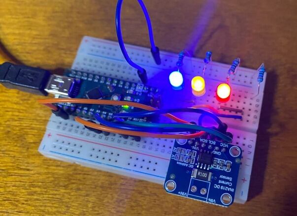
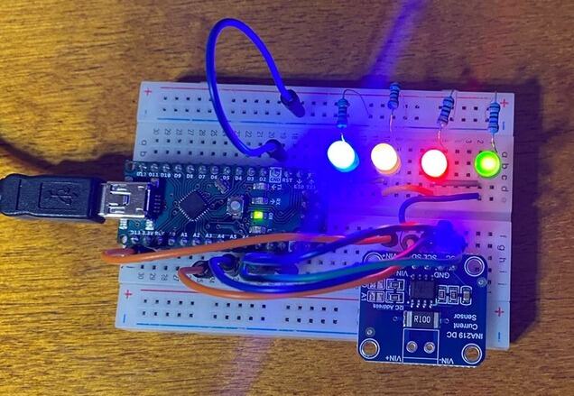
Practical Test Circuit
For practical testing, I have used 4 LED of different color like red, green, yellow & blue. This will help to test the current, voltage and power.

For testing I used breadboard and Arduino Nano.

Source Code/Program
Here is a sample code for interfacing INA219 Current Sensor module with Arduino. The code requires Adafruit INA219 for compilation. Therefore download the library and add it to the library folder.
|
1 2 3 4 5 6 7 8 9 10 11 12 13 14 15 16 17 18 19 20 21 22 23 24 25 26 27 28 29 30 31 32 33 34 35 36 37 38 39 40 41 42 43 44 45 46 47 48 49 50 51 52 53 |
#include <Wire.h> #include <Adafruit_INA219.h> Adafruit_INA219 ina219; void setup(void) { Serial.begin(9600); while (!Serial) { delay(1); } // Initialize the INA219. if (! ina219.begin()) { Serial.println("Failed to find INA219 chip"); while (1) { delay(10); } } // To use a slightly lower 32V, 1A range (higher precision on amps): //ina219.setCalibration_32V_1A(); // Or to use a lower 16V, 400mA range, call: //ina219.setCalibration_16V_400mA(); Serial.println("Measuring voltage, current, and power with INA219 ..."); } void loop(void) { float shuntvoltage = 0; float busvoltage = 0; float current_mA = 0; float loadvoltage = 0; float power_mW = 0; shuntvoltage = ina219.getShuntVoltage_mV(); busvoltage = ina219.getBusVoltage_V(); current_mA = ina219.getCurrent_mA(); power_mW = ina219.getPower_mW(); loadvoltage = busvoltage + (shuntvoltage / 1000); Serial.print("Bus Voltage: "); Serial.print(busvoltage); Serial.println(" V"); Serial.print("Shunt Voltage: "); Serial.print(shuntvoltage); Serial.println(" mV"); Serial.print("Load Voltage: "); Serial.print(loadvoltage); Serial.println(" V"); Serial.print("Current: "); Serial.print(current_mA); Serial.println(" mA"); Serial.print("Power: "); Serial.print(power_mW); Serial.println(" mW"); Serial.println(""); delay(1000); } |
The following lines sets different ranges for the INA219 current sensor.
|
1 2 3 4 |
// To use a slightly lower 32V, 1A range (higher precision on amps): ina219.setCalibration_32V_1A(); // Or to use a lower 16V, 400mA range, call: ina219.setCalibration_16V_400mA(); |
By default, the INA219 sensor is initialized with a range of 32V and 2A. But you can change this default setting to calibrate for different ranges, and these commented lines of code show you how to do it.
ina219.setCalibration_32V_1A();calibrates the INA219 for a range up to 32V and 1A. This reduces the maximum current measurement range but increases the precision of current measurements, making them more accurate.ina219.setCalibration_16V_400mA();calibrates the INA219 for a range up to 16V and 400mA. This further reduces both voltage and current measurement range, but in return, it increases the precision for both voltage and current measurements.
Testing & Results of INA219 DC Current Sensor
After uploading the above code the assembled circuit is ready for testing. We will observe the value of Bus Voltage, Shunt Voltage, Load Voltage, Current & Power on Serial Monitor.
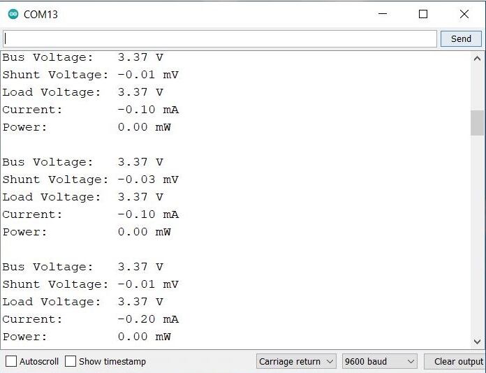
Initially we will not connect any LED to the circuit, and observe the readings.

These are the readings we got without any load.
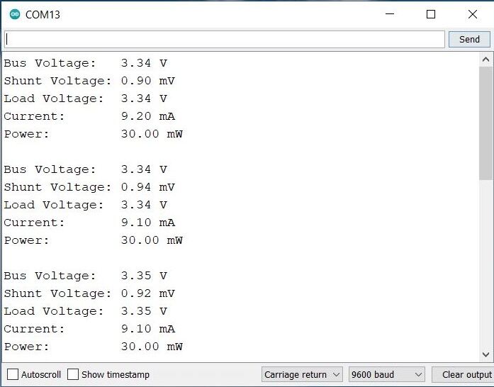
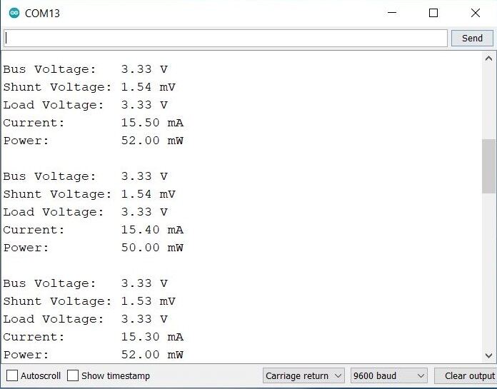
Then we connected 1 LED to the circuit as a load.

The Serial Monitor showed following reading with 1 LED.

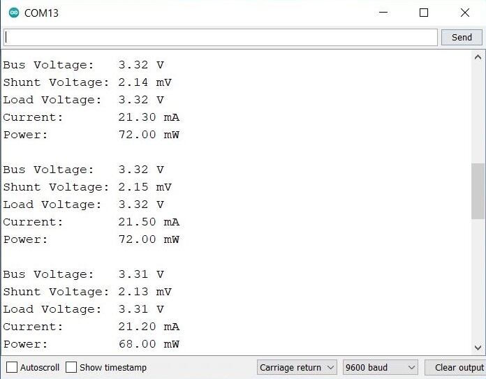
We increased the LED quantity to 2.

With increase in LED quantity, the value of current, voltage and power increased.
The we increased the LED quantity to 3.
This further incread the power consumption.
Then we conducted the final testing with 4 LEDs.
With 4 LEDs the power consumption was maximum.
You can increase the LED more and more or may add a 5V DC Motor to observe the change in reading of voltage, current and power.
Conclusion
The tutorial demonstrated the capability of the INA219 DC Current Sensor Module interfaced with Arduino to measure and monitor voltage, current, and power. Through a series of tests using LEDs as the load, it was established that the INA219 module can accurately track changes in power consumption. It was observed that as the quantity of LEDs increased, the power consumption, along with current and voltage, also increased accordingly. This direct relationship between the load increase and the values of voltage, current, and power confirms the reliability and efficacy of the INA219 module in accurately detecting and monitoring changes in these parameters.

")


4 Comments
Which software you used to draw the circuit diagram? How did you add the sensor in that?
You can use Fritzing software to draw the schematic.
Hi, trying to implement a bunch of these INA 219. Unfortunately i can’t use the 16 adresses. A soon a i connect A0 or A1 to SCL or SDA, communication is lost. It seems that if there only pads to ground is for the reason that the 16 adresses are not usable as stated in the datasheet. This is very frustrating 😦
You need to remove the pull up resistor if you want to connect it to SDA or SCL.