

Overview
In this project, we will build a DC Energy Meter using Arduino that can measure voltage, current, power, and energy consumption.
I recently came across a neat custom-made DC energy meter module from Mutex Embedded. This small but powerful board can measure DC parameters such as voltage (0–32 V range), current (up to 5 A), power, and cumulative energy consumption. It communicates easily over the I²C protocol, making it ideal for direct use with Arduino.
For this guide, I’ll show you how to connect the module to an Arduino and display the live energy meter data on a 16×2 I²C LCD display. The LCD cycles through values of voltage, current, power, and energy, so you can view the parameters in real time without needing a computer.
If you want to take it further, the same module also includes an ESP32 chip option for IoT applications, where the readings can be uploaded to a web server for remote monitoring. But in this guide, we’ll focus only on the Arduino + LCD setup. This project is a simple yet very practical way to track DC energy usage for your electronics, battery projects, or renewable energy experiments. You may use the same DC power module to make an IoT DC Energy meter with ESP32 and view the live data on Webserver.
Bill of Materials
We need following components to build this Arduino DC Energy Meter project.
| S.N. | Components Name | Quantity | Purchase Link |
|---|---|---|---|
| 1 | Arduino Nano Board | 1 | Amazon | AliExpress |
| 2 | DC Power Monitor Module | 1 | Mutex-Embedded |
| 3 | 16x2 LCD Display | 1 | Amazon | AliExpress |
| 4 | Connecting Wires | 10 | Amazon | AliExpress |
| 5 | Breadboard | 1 | Amazon | AliExpress |
DC Power Monitor Module

The DC Power Monitoring Module is a feature-rich solution for tracking voltage, current, power, and energy consumption across four independent channels. At its core is the ESP32-S2 microcontroller, ensuring high performance and IoT readiness. Current measurement is handled through precision high-wattage shunt resistors, while an onboard SD card slot enables real-time data logging. A CR1220 coin cell holder powers the real-time clock, allowing accurate time-stamping of measurements even when the main supply is off.

On the hardware side, the board includes a tiny rear connector that works with a dedicated power extension board, which provides a USB-to-serial interface, micro-USB port, and reset switch. With support for up to 32 V input voltage and 5 A current per channel, the module is well-suited for monitoring small to medium DC appliances or battery systems.

The module supports both I²C and Modbus RTU (UART/RS485) interfaces, making it compatible with a wide range of microcontrollers, including Arduino and ESP32. Data can also be logged to the SD card for up to a year, with weekly historical summaries available for long-term analysis. To simplify user experience, a free PC application is provided for configuration, live monitoring, and firmware updates.
Features & Specifications
- Voltage range: 0 – 32V
- Current range 0 – 5A
- 4 – Channels with common GND
- Serial Interface: I2C + UART Modbus
- RS-485 Bus extension
- Real-Time Clock
- Micro SD Card Data Logging
- PC Application
- Built for Industrial use
Useful Links
Interfacing the DC Energy Meter with Arduino
The DC Power Monitor Module supports both I²C and Modbus RTU communication protocols. In this project, we will be using the I²C interface to connect the module with an Arduino and build our own DC Energy Meter.
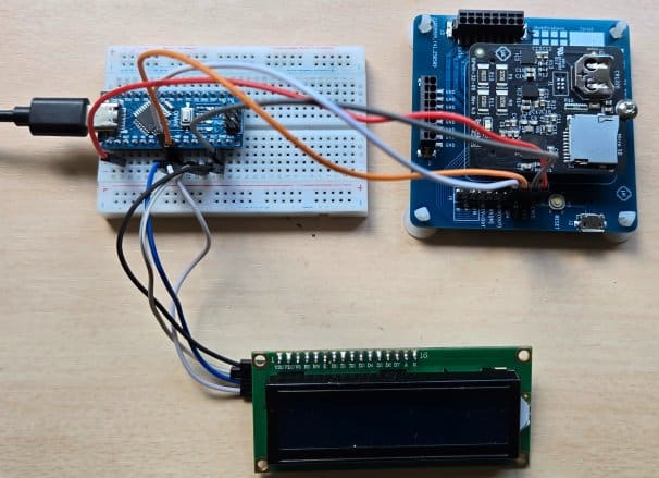
Hardware & Circuit
The wiring is very straightforward. Connect the VCC pin of the Power Monitor Module to the 3.3V pin on the Arduino, and connect the GND pin to the Arduino GND. Then, link the communication lines by connecting the module’s SDA pin to the Arduino’s A4 pin and the SCL pin to the Arduino’s A5 pin.
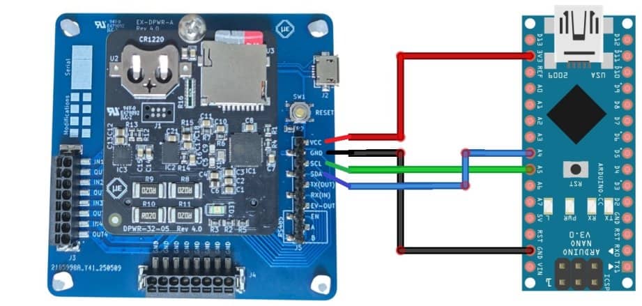
With just these four simple connections, the Arduino will be able to read voltage, current, power, and energy data directly from the module over the I²C bus.
Power Supply & Load Connection
To begin, we need to connect a DC supply and a load to the Power Monitor Module. The board provides four input/output channels labeled IN1–IN4 and OUT1–OUT4. In this example, we will be using Channel 1.
- Connect the Supply
Take any DC supply, such as a battery or a regulated DC adapter. Connect the positive terminal of the supply to the IN1 terminal. The negative (ground) terminal of the supply should be connected to the GND line provided on the module. - Connect the Load
For the load connection, wire the positive terminal of your load (e.g., a DC motor, lamp, or electronic circuit) to the OUT1 terminal. The negative terminal of the load should also be connected to the common GND of the module.
That’s all that is needed—the module will now measure the supply voltage, the current flowing through the load, and automatically calculate power and energy consumption for Channel 1.
I2C Library (MbI2C_ArduinoPort.h)
The developer of this product has already created a library for the DC Power Monitor Module. Although it was originally written for another microcontroller, I have adapted the same library and used it in this Arduino project to read data via the I²C interface.
Create a folder anywhere in your computer and name it as “mb_energy_meter“. Inside the folder create a text file and save it as “MbI2C_ArduinoPort.h“. Copy the following library code and paste it in the .h file and save it.
|
1 2 3 4 5 6 7 8 9 10 11 12 13 14 15 16 17 18 19 20 21 22 23 24 25 26 27 28 29 30 31 32 33 34 35 36 37 38 39 40 41 42 43 44 45 46 47 48 49 50 51 52 53 54 55 56 57 58 59 60 61 62 63 64 65 66 67 68 69 70 71 72 73 74 75 76 77 78 79 80 81 82 83 84 85 86 87 88 89 90 91 92 93 94 95 96 97 98 99 100 101 102 103 104 105 106 107 108 109 110 111 112 113 114 115 116 117 118 119 120 121 122 123 124 125 126 127 128 129 130 131 132 133 134 135 136 137 138 139 140 141 142 143 144 145 146 147 148 149 150 151 152 153 154 155 156 157 158 159 160 161 162 163 164 165 166 167 168 169 170 171 172 173 174 175 176 177 178 179 180 181 182 183 184 185 186 187 188 189 190 191 192 193 194 195 196 197 198 199 200 201 202 203 204 205 206 207 208 209 210 211 212 213 214 215 216 217 218 219 220 221 222 223 224 225 226 227 228 229 230 231 232 233 234 235 236 237 238 239 240 241 242 243 244 245 246 247 248 249 250 251 252 253 254 255 256 257 258 259 260 261 262 263 264 265 266 267 268 269 270 271 272 273 274 275 276 277 278 279 280 281 282 283 284 285 286 287 288 289 290 291 292 293 294 295 296 297 298 299 300 301 302 303 304 305 306 307 308 309 310 311 312 313 314 315 316 317 318 319 320 321 322 323 324 325 326 327 328 329 330 331 332 333 334 335 336 337 338 339 340 341 342 343 344 345 346 347 348 349 350 351 352 353 354 355 356 357 358 359 360 361 362 363 364 365 366 367 368 369 370 371 372 373 374 375 376 377 378 379 380 381 382 383 384 385 386 387 388 389 390 391 392 393 394 395 396 397 398 399 400 401 402 403 404 405 406 407 408 409 410 411 412 413 414 415 416 417 418 419 420 421 422 423 424 425 426 427 428 429 430 431 432 433 434 435 436 437 438 439 440 441 442 443 444 445 446 447 448 449 450 |
#include <Arduino.h> #include <Wire.h> #include <stdint.h> #include <string.h> // -------- Original mb_i2c.h content (with include-guard adapted) -------- typedef bool (*I2cWriteCallback_t) (uint8_t slaveAddrs, uint8_t* pDataWr, uint8_t size); typedef bool (*I2cReadCallback_t) (uint8_t slaveAddrs, uint8_t* pDataRd, uint8_t size); typedef uint32_t (*GetMillisCallback_t) (void); typedef void (*DelayCallback_t) (uint32_t msDelay); typedef struct { uint8_t i2cAddress; I2cWriteCallback_t cbWrite; I2cReadCallback_t cbRead; GetMillisCallback_t cbGetMillis; DelayCallback_t cbDelay; } MbI2c_Init_t; typedef struct { MbI2c_Init_t init; bool isInitialized; } MbI2c_Handle_t; typedef enum { MbI2c_RegType_Holding, MbI2c_RegType_Input, } MbI2c_RegType_e; // -------- Constants from mb_i2c.c -------- #ifndef MB_I2C_READ_BUFFER_SIZE #define MB_I2C_READ_BUFFER_SIZE 128 #endif #ifndef MB_I2C_READ_DELAY #define MB_I2C_READ_DELAY 5 #endif #ifndef MB_I2C_READ_TIMEOUT #define MB_I2C_READ_TIMEOUT 100 #endif typedef enum { MbI2c_Cmd_WriteHolding = 1, MbI2c_Cmd_ReadHolding = 2, MbI2c_Cmd_ReadInput = 3 } MbI2c_Cmd_e; // SMBus CRC-8 lookup table static const uint8_t gLookupTableSmbus[256] = { 0x00, 0x07, 0x0e, 0x09, 0x1c, 0x1b, 0x12, 0x15, 0x38, 0x3f, 0x36, 0x31, 0x24, 0x23, 0x2a, 0x2d, 0x70, 0x77, 0x7e, 0x79, 0x6c, 0x6b, 0x62, 0x65, 0x48, 0x4f, 0x46, 0x41, 0x54, 0x53, 0x5a, 0x5d, 0xe0, 0xe7, 0xee, 0xe9, 0xfc, 0xfb, 0xf2, 0xf5, 0xd8, 0xdf, 0xd6, 0xd1, 0xc4, 0xc3, 0xca, 0xcd, 0x90, 0x97, 0x9e, 0x99, 0x8c, 0x8b, 0x82, 0x85, 0xa8, 0xaf, 0xa6, 0xa1, 0xb4, 0xb3, 0xba, 0xbd, 0xc7, 0xc0, 0xc9, 0xce, 0xdb, 0xdc, 0xd5, 0xd2, 0xff, 0xf8, 0xf1, 0xf6, 0xe3, 0xe4, 0xed, 0xea, 0xb7, 0xb0, 0xb9, 0xbe, 0xab, 0xac, 0xa5, 0xa2, 0x8f, 0x88, 0x81, 0x86, 0x93, 0x94, 0x9d, 0x9a, 0x27, 0x20, 0x29, 0x2e, 0x3b, 0x3c, 0x35, 0x32, 0x1f, 0x18, 0x11, 0x16, 0x03, 0x04, 0x0d, 0x0a, 0x57, 0x50, 0x59, 0x5e, 0x4b, 0x4c, 0x45, 0x42, 0x6f, 0x68, 0x61, 0x66, 0x73, 0x74, 0x7d, 0x7a, 0x89, 0x8e, 0x87, 0x80, 0x95, 0x92, 0x9b, 0x9c, 0xb1, 0xb6, 0xbf, 0xb8, 0xad, 0xaa, 0xa3, 0xa4, 0xf9, 0xfe, 0xf7, 0xf0, 0xe5, 0xe2, 0xeb, 0xec, 0xc1, 0xc6, 0xcf, 0xc8, 0xdd, 0xda, 0xd3, 0xd4, 0x69, 0x6e, 0x67, 0x60, 0x75, 0x72, 0x7b, 0x7c, 0x51, 0x56, 0x5f, 0x58, 0x4d, 0x4a, 0x43, 0x44, 0x19, 0x1e, 0x17, 0x10, 0x05, 0x02, 0x0b, 0x0c, 0x21, 0x26, 0x2f, 0x28, 0x3d, 0x3a, 0x33, 0x34, 0x4e, 0x49, 0x40, 0x47, 0x52, 0x55, 0x5c, 0x5b, 0x76, 0x71, 0x78, 0x7f, 0x6a, 0x6d, 0x64, 0x63, 0x3e, 0x39, 0x30, 0x37, 0x22, 0x25, 0x2c, 0x2b, 0x06, 0x01, 0x08, 0x0f, 0x1a, 0x1d, 0x14, 0x13, 0xae, 0xa9, 0xa0, 0xa7, 0xb2, 0xb5, 0xbc, 0xbb, 0x96, 0x91, 0x98, 0x9f, 0x8a, 0x8d, 0x84, 0x83, 0xde, 0xd9, 0xd0, 0xd7, 0xc2, 0xc5, 0xcc, 0xcb, 0xe6, 0xe1, 0xe8, 0xef, 0xfa, 0xfd, 0xf4, 0xf3 }; static uint8_t gReadBuffer[MB_I2C_READ_BUFFER_SIZE]; // -------- Internal functions from mb_i2c.c -------- static uint8_t mbI2c_smbus_calculate (uint8_t* pData, uint16_t size) { uint8_t crcByte = 0; for(uint16_t i = 0; i < size; i++) { crcByte = gLookupTableSmbus[crcByte ^ pData[i]]; } return crcByte; } static bool mbI2c_smbus_verify (uint8_t* pData, uint16_t size, uint8_t crc) { uint8_t crcByte = mbI2c_smbus_calculate(pData, size); return (crcByte == crc); } static bool mbI2c_readData (MbI2c_Handle_t* pHandle, uint16_t* pData, uint16_t len) { uint8_t lenBytes = len * 2; bool i2cStatus = false; uint32_t startTicks = pHandle->init.cbGetMillis(); do { if(pHandle->init.cbRead(pHandle->init.i2cAddress, gReadBuffer, lenBytes + 1)) { uint8_t crcValue = gReadBuffer[lenBytes]; bool crcState = mbI2c_smbus_verify(gReadBuffer, lenBytes, crcValue); if(crcState) { memcpy(pData, gReadBuffer, lenBytes); i2cStatus = true; break; } else { i2cStatus = false; } } else { i2cStatus = false; } } while ((pHandle->init.cbGetMillis() - startTicks) < MB_I2C_READ_TIMEOUT); return i2cStatus; } // -------- Public API from mb_i2c.c -------- static bool mbI2c_init (MbI2c_Init_t* pInit, MbI2c_Handle_t* pHandle) { if((pInit->cbWrite != NULL) && (pInit->cbRead != NULL) && (pInit->cbGetMillis != NULL) && (pInit->cbDelay != NULL)) { memcpy(&pHandle->init, pInit, sizeof(MbI2c_Init_t)); pHandle->isInitialized = true; return true; } pHandle->isInitialized = false; return false; } static bool mbI2c_writeHolding (MbI2c_Handle_t* pHandle, uint16_t regAddrs, uint16_t* pWriteBuf, uint16_t len) { if(!pHandle->isInitialized) { return false; } bool i2cStatus = true; uint8_t cmdPacket[5] = {0}; cmdPacket[0] = MbI2c_Cmd_WriteHolding; cmdPacket[1] = (regAddrs & 0xFF); cmdPacket[2] = ((regAddrs >> 8) & 0xFF); cmdPacket[3] = len; cmdPacket[4] = mbI2c_smbus_calculate(cmdPacket, 4); i2cStatus = pHandle->init.cbWrite(pHandle->init.i2cAddress, cmdPacket, 5); if(i2cStatus) { i2cStatus = pHandle->init.cbWrite(pHandle->init.i2cAddress, (uint8_t*)pWriteBuf, len * 2); } if(i2cStatus) { uint8_t crcValue = mbI2c_smbus_calculate((uint8_t*)pWriteBuf, len * 2); i2cStatus = pHandle->init.cbWrite(pHandle->init.i2cAddress, (uint8_t*)&crcValue, 1); } return i2cStatus; } static bool mbI2c_readHolding (MbI2c_Handle_t* pHandle, uint16_t regAddrs, uint16_t* pReadBuf, uint16_t len) { if(!pHandle->isInitialized) { return false; } uint8_t cmdPacket[5] = {0}; cmdPacket[0] = MbI2c_Cmd_ReadHolding; cmdPacket[1] = (regAddrs & 0xFF); cmdPacket[2] = ((regAddrs >> 8) & 0xFF); cmdPacket[3] = len; cmdPacket[4] = mbI2c_smbus_calculate(cmdPacket, 4); bool i2cStatus = pHandle->init.cbWrite(pHandle->init.i2cAddress, cmdPacket, 5); if(i2cStatus) { pHandle->init.cbDelay(MB_I2C_READ_DELAY); i2cStatus = mbI2c_readData(pHandle, pReadBuf, len); } return i2cStatus; } static bool mbI2c_readInput (MbI2c_Handle_t* pHandle, uint16_t regAddrs, uint16_t* pReadBuf, uint16_t len) { if(!pHandle->isInitialized) { return false; } uint8_t cmdPacket[5] = {0}; cmdPacket[0] = MbI2c_Cmd_ReadInput; cmdPacket[1] = (regAddrs & 0xFF); cmdPacket[2] = ((regAddrs >> 8) & 0xFF); cmdPacket[3] = len; cmdPacket[4] = mbI2c_smbus_calculate(cmdPacket, 4); bool i2cStatus = pHandle->init.cbWrite(pHandle->init.i2cAddress, cmdPacket, 5); if(i2cStatus) { pHandle->init.cbDelay(MB_I2C_READ_DELAY); i2cStatus = mbI2c_readData(pHandle, pReadBuf, len); } return i2cStatus; } static bool mbI2c_writeHoldingUint16 (MbI2c_Handle_t* pHandle, uint16_t regAddrs, uint16_t data) { return mbI2c_writeHolding(pHandle, regAddrs, &data, 1); } static bool mbI2c_writeHoldingInt16 (MbI2c_Handle_t* pHandle, uint16_t regAddrs, int16_t data) { return mbI2c_writeHolding(pHandle, regAddrs, (uint16_t*)&data, 1); } static bool mbI2c_writeHoldingUint32 (MbI2c_Handle_t* pHandle, uint16_t regAddrs, uint32_t data) { return mbI2c_writeHolding(pHandle, regAddrs, (uint16_t*)&data, 2); } static bool mbI2c_writeHoldingInt32 (MbI2c_Handle_t* pHandle, uint16_t regAddrs, int32_t data) { return mbI2c_writeHolding(pHandle, regAddrs, (uint16_t*)&data, 2); } static bool mbI2c_writeHoldingBool (MbI2c_Handle_t* pHandle, uint16_t regAddrs, bool data) { uint16_t data16 = data; return mbI2c_writeHolding(pHandle, regAddrs, &data16, 1); } static bool mbI2c_writeHoldingFloat (MbI2c_Handle_t* pHandle, uint16_t regAddrs, float data) { return mbI2c_writeHolding(pHandle, regAddrs, (uint16_t*)&data, 2); } static bool mbI2c_readUint16 (MbI2c_Handle_t* pHandle, uint16_t regAddrs, uint16_t* pReadData, MbI2c_RegType_e regType) { if(regType == MbI2c_RegType_Holding) { return mbI2c_readHolding(pHandle, regAddrs, pReadData, 1); } else { return mbI2c_readInput(pHandle, regAddrs, pReadData, 1); } } static bool mbI2c_readInt16 (MbI2c_Handle_t* pHandle, uint16_t regAddrs, int16_t* pReadData, MbI2c_RegType_e regType) { if(regType == MbI2c_RegType_Holding) { return mbI2c_readHolding(pHandle, regAddrs, (uint16_t*)pReadData, 1); } else { return mbI2c_readInput(pHandle, regAddrs, (uint16_t*)pReadData, 1); } } static bool mbI2c_readUint32 (MbI2c_Handle_t* pHandle, uint16_t regAddrs, uint32_t* pReadData, MbI2c_RegType_e regType) { if(regType == MbI2c_RegType_Holding) { return mbI2c_readHolding(pHandle, regAddrs, (uint16_t*)pReadData, 2); } else { return mbI2c_readInput(pHandle, regAddrs, (uint16_t*)pReadData, 2); } } static bool mbI2c_readInt32 (MbI2c_Handle_t* pHandle, uint16_t regAddrs, int32_t* pReadData, MbI2c_RegType_e regType) { if(regType == MbI2c_RegType_Holding) { return mbI2c_readHolding(pHandle, regAddrs, (uint16_t*)pReadData, 2); } else { return mbI2c_readInput(pHandle, regAddrs, (uint16_t*)pReadData, 2); } } static bool mbI2c_readBool (MbI2c_Handle_t* pHandle, uint16_t regAddrs, bool* pReadData, MbI2c_RegType_e regType) { uint16_t data16 = 0; bool status = true; if(regType == MbI2c_RegType_Holding) { status = mbI2c_readHolding(pHandle, regAddrs, &data16, 1); } else { status = mbI2c_readInput(pHandle, regAddrs, &data16, 1); } *pReadData = (bool)data16; return status; } static bool mbI2c_readFloat (MbI2c_Handle_t* pHandle, uint16_t regAddrs, float* pReadData, MbI2c_RegType_e regType) { if(regType == MbI2c_RegType_Holding) { return mbI2c_readHolding(pHandle, regAddrs, (uint16_t*)pReadData, 2); } else { return mbI2c_readInput(pHandle, regAddrs, (uint16_t*)pReadData, 2); } } // -------- Arduino Wire() callbacks (plug into MbI2c_Init_t) -------- static bool ArduinoI2C_Write(uint8_t addr7, uint8_t* pDataWr, uint8_t size) { Wire.beginTransmission(addr7); size_t n = Wire.write(pDataWr, size); uint8_t err = Wire.endTransmission(true); // send STOP return (err == 0) && (n == size); } static bool ArduinoI2C_Read(uint8_t addr7, uint8_t* pDataRd, uint8_t size) { // One request for 'size' bytes; then pull them out. // Note: classic AVR Wire has a 32-byte rx buffer limit. uint32_t start = millis(); uint8_t got = Wire.requestFrom((int)addr7, (int)size, (int)true); while ( (Wire.available() < got) && (millis() - start < MB_I2C_READ_TIMEOUT) ) { // wait briefly if somehow not all are queued yet delay(1); } if (got < size) { // If the peripheral returned fewer bytes, fill what we have and fail for (uint8_t i=0; i<got; ++i) pDataRd[i] = (uint8_t)Wire.read(); return false; } for (uint8_t i=0; i<size; ++i) pDataRd[i] = (uint8_t)Wire.read(); return true; } static uint32_t ArduinoMillis() { return millis(); } static void ArduinoDelay(uint32_t ms) { delay(ms); } // Helper to quickly set up a handle for Arduino Wire static bool MbI2c_BeginArduino(MbI2c_Handle_t* pHandle, uint8_t i2cAddress) { MbI2c_Init_t init; init.i2cAddress = i2cAddress; init.cbWrite = ArduinoI2C_Write; init.cbRead = ArduinoI2C_Read; init.cbGetMillis = ArduinoMillis; init.cbDelay = ArduinoDelay; return mbI2c_init(&init, pHandle); } // -------- Portable typed-read helpers (endianness & word-order control) ----- static inline uint16_t bswap16(uint16_t v) { return (uint16_t)((v >> 8) | (v << 8)); } static inline void swap16(uint16_t& a, uint16_t& b) { uint16_t t=a; a=b; b=t; } /* * Many metering ICs return: * - 16-bit words big-endian (byte order inside each 16-bit is MSB first), * - and a 32-bit value as two 16-bit words that may be [HiWord, LoWord] or [LoWord, HiWord]. * * Use these helpers to normalize into native CPU ordering for float/uint32. */ static bool mbRead2Words(MbI2c_Handle_t* h, uint16_t reg, MbI2c_RegType_e type, bool swapBytesEachWord, bool swapWordOrder, uint16_t outWords[2]) { uint16_t tmp[2] = {0,0}; bool ok = (type == MbI2c_RegType_Holding) ? mbI2c_readHolding(h, reg, tmp, 2) : mbI2c_readInput(h, reg, tmp, 2); if (!ok) return false; // optional byte swap within each 16-bit if (swapBytesEachWord) { tmp[0] = bswap16(tmp[0]); tmp[1] = bswap16(tmp[1]); } // optional word swap for 32-bit values if (swapWordOrder) swap16(tmp[0], tmp[1]); outWords[0] = tmp[0]; outWords[1] = tmp[1]; return true; } static bool mbReadFloatPortable(MbI2c_Handle_t* h, uint16_t reg, MbI2c_RegType_e type, bool swapBytesEachWord, bool swapWordOrder, float* out) { uint16_t w[2]; if (!mbRead2Words(h, reg, type, swapBytesEachWord, swapWordOrder, w)) return false; memcpy(out, w, sizeof(w)); // now in native layout return true; } static bool mbReadUint32Portable(MbI2c_Handle_t* h, uint16_t reg, MbI2c_RegType_e type, bool swapBytesEachWord, bool swapWordOrder, uint32_t* out) { uint16_t w[2]; if (!mbRead2Words(h, reg, type, swapBytesEachWord, swapWordOrder, w)) return false; memcpy(out, w, sizeof(w)); return true; } static bool mbReadUint16Portable(MbI2c_Handle_t* h, uint16_t reg, MbI2c_RegType_e type, bool swapBytesWord, uint16_t* out) { uint16_t v = 0; if (!( (type == MbI2c_RegType_Holding) ? mbI2c_readHolding(h, reg, &v, 1) : mbI2c_readInput(h, reg, &v, 1))) return false; if (swapBytesWord) v = bswap16(v); *out = v; return true; } |
Source Code/Program (DC Energy Meter using Arduino)
This Arduino sketch communicates with the DC Power Monitor Module over the I²C bus and continuously reads voltage, current, power, and total energy from Channel 1. It converts the raw register data into real-world units and prints the measurements to the Serial Monitor every 500 ms. It also performs an optional firmware version check during setup.
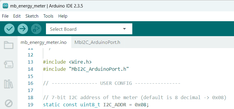
Create a new file on the folder that you created earlier and save it with a name “mb_energy_meter.ino“. Paste the following code on the ino file. Then open the Arduino code.
|
1 2 3 4 5 6 7 8 9 10 11 12 13 14 15 16 17 18 19 20 21 22 23 24 25 26 27 28 29 30 31 32 33 34 35 36 37 38 39 40 41 42 43 44 45 46 47 48 49 50 51 52 53 54 55 56 57 58 59 60 61 62 63 64 65 66 67 68 69 70 71 72 73 74 75 76 77 78 79 80 81 82 83 84 85 86 87 88 89 90 91 92 93 94 95 96 97 98 99 100 101 102 103 104 105 106 107 108 109 110 111 112 113 114 115 116 117 118 119 120 121 122 123 124 125 126 127 128 129 130 131 132 |
/* * DCEnergyMeter_CH1_I2C.ino * * Reads Channel 1 Voltage / Current / Power / Total Energy from the DPWR meter * over I2C, and prints to Serial. * * REQUIREMENTS: * - Put MbI2C_ArduinoPort.h (from our previous message) next to this .ino * - Wire I2C to your Arduino (SDA/SCL) and set the correct I2C address * - Channel 1 must be wired and powered per the manual */ #include <Wire.h> #include "MbI2C_ArduinoPort.h" // ---------------- USER CONFIG ---------------- // 7-bit I2C address of the meter (default is 8 decimal -> 0x08) static const uint8_t I2C_ADDR = 0x08; // Channel 1 Input register addresses (32-bit values in 2x16-bit regs): // (decimal addresses from the manual) static const uint16_t REG_VOLTAGE = 80; // CH1 Voltage (U32) -> V static const uint16_t REG_CURRENT = 82; // CH1 Current (U32) -> A static const uint16_t REG_POWER = 84; // CH1 Power (U32) -> W static const uint16_t REG_ENERGY = 88; // CH1 Total Energy (U32) -> Wh // All are "Input" registers static const MbI2c_RegType_e VOLTAGE_TYPE = MbI2c_RegType_Input; static const MbI2c_RegType_e CURRENT_TYPE = MbI2c_RegType_Input; static const MbI2c_RegType_e POWER_TYPE = MbI2c_RegType_Input; static const MbI2c_RegType_e ENERGY_TYPE = MbI2c_RegType_Input; // Endianness from the manual: // - each 16-bit word is transmitted MSB-first (big-endian on the wire) // - 32-bit values are two words in order [LowWord, HighWord] static const bool BYTES_BIG_ENDIAN_IN_WORDS = false; static const bool SWAP_WORDS_32BIT = false; // order already [Lo, Hi] // Scaling: the device returns scaled integers; apply 0.001 to get engineering units static const float VOLT_SCALE = 0.001f; // V per LSB static const float CURR_SCALE = 0.001f; // A per LSB static const float POWR_SCALE = 0.001f; // W per LSB static const float ENER_SCALE = 0.001f; // Wh per LSB // Sample period (ms) static const uint32_t SAMPLE_MS = 500; // ---------------- END USER CONFIG ---------------- MbI2c_Handle_t gMeter; // ---- Typed read helpers for this sketch ---- bool readU32Scaled(uint16_t reg, MbI2c_RegType_e type, float scale, float& outVal) { uint32_t raw = 0; if (!mbReadUint32Portable(&gMeter, reg, type, BYTES_BIG_ENDIAN_IN_WORDS, SWAP_WORDS_32BIT, &raw)) return false; outVal = raw * scale; return true; } bool readVoltage(float& v) { return readU32Scaled(REG_VOLTAGE, VOLTAGE_TYPE, VOLT_SCALE, v); } bool readCurrent(float& a) { return readU32Scaled(REG_CURRENT, CURRENT_TYPE, CURR_SCALE, a); } bool readPower (float& w) { return readU32Scaled(REG_POWER, POWER_TYPE, POWR_SCALE, w); } bool readEnergy (float& e) { return readU32Scaled(REG_ENERGY, ENERGY_TYPE, ENER_SCALE, e); } // Optional: read 16-bit firmware version fields to confirm non-zero reads bool readFirmwareVersion(uint16_t& major, uint16_t& minor) { // FW version (example): Input regs 48 = major, 49 = minor // Use 16-bit portable read to swap bytes if needed. if (!mbReadUint16Portable(&gMeter, 48, MbI2c_RegType_Input, BYTES_BIG_ENDIAN_IN_WORDS, &major)) return false; if (!mbReadUint16Portable(&gMeter, 49, MbI2c_RegType_Input, BYTES_BIG_ENDIAN_IN_WORDS, &minor)) return false; return true; } void setup() { Serial.begin(115200); while (!Serial) { /* wait for Serial on native USB boards */ } Wire.begin(); // join I2C bus Wire.setClock(400000); // try fast-mode; if bus is long/noisy, use 100000 if (!MbI2c_BeginArduino(&gMeter, I2C_ADDR)) { Serial.println(F("ERROR: Meter init failed (callbacks).")); for(;;) { delay(1000); } } Serial.println(F("DC Energy Meter (CH1) over I2C")); Serial.print(F("I2C address = 0x")); Serial.println(I2C_ADDR, HEX); // Optional sanity check: firmware version uint16_t fwMaj=0, fwMin=0; if (readFirmwareVersion(fwMaj, fwMin)) { Serial.print(F("FW version: ")); Serial.print(fwMaj); Serial.print(F(".")); Serial.println(fwMin); } else { Serial.println(F("FW version read failed (optional check).")); } } void loop() { float v=0, a=0, w=0, e=0; bool okV = readVoltage(v); bool okA = readCurrent(a); bool okW = readPower(w); bool okE = readEnergy(e); // Wh (total) if (okV && okA && okW && okE) { Serial.print(F("V=")); Serial.print(v, 3); Serial.print(F(" V ")); Serial.print(F("I=")); Serial.print(a, 3); Serial.print(F(" A ")); Serial.print(F("P=")); Serial.print(w, 3); Serial.print(F(" W ")); Serial.print(F("E=")); Serial.print(e, 3); Serial.println(F(" Wh")); } else { Serial.print(F("Read error(s): ")); if (!okV) Serial.print(F("[V] ")); if (!okA) Serial.print(F("[I] ")); if (!okW) Serial.print(F("[P] ")); if (!okE) Serial.print(F("[E] ")); Serial.println(); } delay(SAMPLE_MS); } |
Testing the Arduino DC Energy Meter
In the Arduino IDE, go to the Board Manager and select Arduino Nano (or the board you are using). Choose the correct COM port, then click on the Upload button to flash the code onto the board.
Once the upload is complete, open the Serial Monitor from the Arduino IDE. Set the baud rate to the value used in your code (e.g., 115200).
Make sure the DC Power Monitor Module is supplied with a suitable DC source such as a battery or a variable DC power supply. Also, connect a load (for example, an LED, a DC motor, or any small DC appliance) to the selected channel.
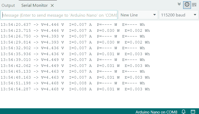
When everything is connected, you should start seeing real-time readings of voltage, current, power, and energy appear in the Serial Monitor.
Displaying the DC Energy Meter on LCD with Arduino
So far, we have displayed the DC Energy Meter readings on the Serial Monitor. Now, let’s show the same measurements on a 16×2 I²C LCD display.
Hardware & Circuit
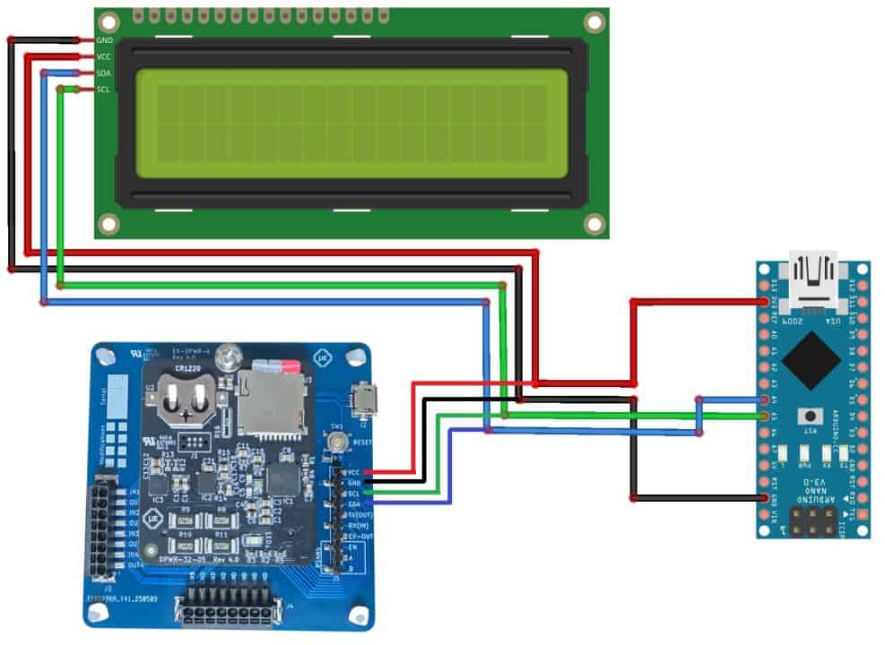
The LCD is powered from the Arduino’s 5V supply and communicates using the I²C interface. Simply connect the LCD’s SDA and SCL pins to the corresponding I²C pins of the Arduino (A4 for SDA and A5 for SCL on Arduino Uno/Nano).
Once connected, the real-time values of voltage, current, power, and energy can be displayed directly on the LCD screen for easy monitoring without needing a computer.
Source Code/Program
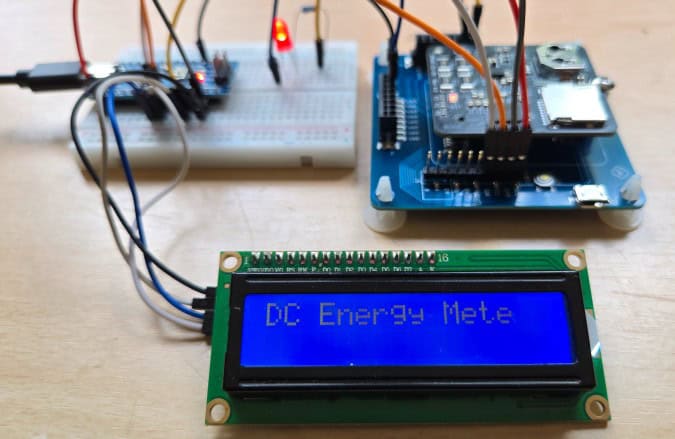
This code reads voltage, current, power, and energy values from the DC Power Monitor Module via I²C and displays them on a 16×2 LCD. It first shows a splash screen for four seconds, then alternates every three seconds between voltage/current and power/energy readings, while also printing the same data to the Serial Monitor.
Copy the following code and paste it on your main ino file. You need to add LiquidCrystal I2C to the Arduino library folder. You also need the above mentioned energy meter I2C library for reading the energy meter data.
|
1 2 3 4 5 6 7 8 9 10 11 12 13 14 15 16 17 18 19 20 21 22 23 24 25 26 27 28 29 30 31 32 33 34 35 36 37 38 39 40 41 42 43 44 45 46 47 48 49 50 51 52 53 54 55 56 57 58 59 60 61 62 63 64 65 66 67 68 69 70 71 72 73 74 75 76 77 78 79 80 81 82 83 84 85 86 87 88 89 90 91 92 93 94 95 96 97 98 99 100 101 102 103 104 105 106 107 108 109 110 111 112 113 114 115 116 117 118 119 120 121 122 123 124 125 126 127 128 129 130 131 132 133 134 135 136 137 138 139 140 141 142 143 144 145 146 147 148 149 150 151 152 153 154 155 156 157 158 159 160 161 162 163 164 165 166 167 168 169 170 171 172 173 174 175 |
/* * DCEnergyMeter_CH1_I2C_LCD.ino * * - Reads Channel 1 Voltage / Current / Power / Total Energy from the DPWR meter over I2C * - Shows a 4s splash screen "DC Energy Meter" * - Then alternates every 3s: * Page A: V on line 1, I on line 2 * Page B: P on line 1, E on line 2 * * REQUIREMENTS: * - Put MbI2C_ArduinoPort.h (from earlier) next to this .ino * - Install LiquidCrystal_I2C library (by Frank de Brabander, or compatible) * - Set LCD_ADDR (0x27 is common; sometimes 0x3F) * - I2C address of meter = 0x08 (7-bit) */ #include <Wire.h> #include <LiquidCrystal_I2C.h> #include "MbI2C_ArduinoPort.h" // ---------------- USER CONFIG ---------------- // LCD config static const uint8_t LCD_ADDR = 0x27; // <-- change to 0x3F if your module uses that static const uint8_t LCD_COLS = 16; static const uint8_t LCD_ROWS = 2; // Meter I2C address (7-bit) static const uint8_t I2C_ADDR = 0x08; // default per manual // Channel 1 Input register addresses (32-bit values in 2x16-bit regs), decimal: static const uint16_t REG_VOLTAGE = 80; // CH1 Voltage (U32) -> V static const uint16_t REG_CURRENT = 82; // CH1 Current (U32) -> A static const uint16_t REG_POWER = 84; // CH1 Power (U32) -> W static const uint16_t REG_ENERGY = 88; // CH1 Total Energy (U32) -> Wh // All are Input registers static const MbI2c_RegType_e VOLTAGE_TYPE = MbI2c_RegType_Input; static const MbI2c_RegType_e CURRENT_TYPE = MbI2c_RegType_Input; static const MbI2c_RegType_e POWER_TYPE = MbI2c_RegType_Input; static const MbI2c_RegType_e ENERGY_TYPE = MbI2c_RegType_Input; // Endianness discovered (do not swap bytes or words): static const bool BYTES_BIG_ENDIAN_IN_WORDS = false; // each 16-bit word already correct static const bool SWAP_WORDS_32BIT = false; // order [Lo, Hi] // Scaling: device returns scaled integers; apply 0.001 to get engineering units static const float VOLT_SCALE = 0.001f; // V per LSB static const float CURR_SCALE = 0.001f; // A per LSB static const float POWR_SCALE = 0.001f; // W per LSB static const float ENER_SCALE = 0.001f; // Wh per LSB // Timings static const uint32_t BOOT_SPLASH_MS = 4000; static const uint32_t PAGE_HOLD_MS = 3000; // ---------------- END USER CONFIG ---------------- LiquidCrystal_I2C lcd(LCD_ADDR, LCD_COLS, LCD_ROWS); MbI2c_Handle_t gMeter; // ---- Typed read helpers ---- bool readU32Scaled(uint16_t reg, MbI2c_RegType_e type, float scale, float& outVal) { uint32_t raw = 0; if (!mbReadUint32Portable(&gMeter, reg, type, BYTES_BIG_ENDIAN_IN_WORDS, SWAP_WORDS_32BIT, &raw)) return false; outVal = raw * scale; return true; } bool readVoltage(float& v) { return readU32Scaled(REG_VOLTAGE, VOLTAGE_TYPE, VOLT_SCALE, v); } bool readCurrent(float& a) { return readU32Scaled(REG_CURRENT, CURRENT_TYPE, CURR_SCALE, a); } bool readPower (float& w) { return readU32Scaled(REG_POWER, POWER_TYPE, POWR_SCALE, w); } bool readEnergy (float& e) { return readU32Scaled(REG_ENERGY, ENERGY_TYPE, ENER_SCALE, e); } // ---- LCD helpers ---- void lcdClear() { lcd.clear(); // small settle delay helps avoid ghosting on some backpacks delay(5); } // prints like "V: 12.345 V" trimmed to 16 chars void lcdPrintValue(uint8_t row, const char* label, float value, const char* unit, uint8_t decimals) { char val[16]; dtostrf(value, 0, decimals, val); // float -> text char line[32]; snprintf(line, sizeof(line), "%s %s %s", label, val, unit); line[LCD_COLS] = '\0'; // truncate to 16 cols just in case lcd.setCursor(0, row); lcd.print(line); } // prints like "V: ----" if read failed void lcdPrintDash(uint8_t row, const char* label, const char* unit) { char line[32]; snprintf(line, sizeof(line), "%s ---- %s", label, unit); line[LCD_COLS] = '\0'; lcd.setCursor(0, row); lcd.print(line); } // (Optional) Serial print for debugging void serialPrintAll(float v, float a, float w, float e, bool okV, bool okA, bool okW, bool okE) { Serial.print(F("V=")); okV ? Serial.print(v,3) : Serial.print(F("----")); Serial.print(F(" V ")); Serial.print(F("I=")); okA ? Serial.print(a,3) : Serial.print(F("----")); Serial.print(F(" A ")); Serial.print(F("P=")); okW ? Serial.print(w,3) : Serial.print(F("----")); Serial.print(F(" W ")); Serial.print(F("E=")); okE ? Serial.print(e,3) : Serial.print(F("----")); Serial.println(F(" Wh")); } void setup() { Serial.begin(115200); while (!Serial) { /* wait for Serial on native USB boards */ } Wire.begin(); // join I2C bus Wire.setClock(100000); // 100 kHz (stable with multiple devices); raise to 400k if you like // Meter init if (!MbI2c_BeginArduino(&gMeter, I2C_ADDR)) { Serial.println(F("ERROR: Meter init failed (callbacks).")); for(;;) { delay(1000); } } // LCD init lcd.init(); lcd.backlight(); lcdClear(); lcd.setCursor(0,0); lcd.print(F("DC Energy Meter")); delay(BOOT_SPLASH_MS); lcdClear(); } void loop() { float v=0, a=0, w=0, e=0; // --- Page A: Voltage & Current --- bool okV = readVoltage(v); bool okA = readCurrent(a); lcdClear(); if (okV) lcdPrintValue(0, "V:", v, "V", 3); else lcdPrintDash (0, "V:", "V"); if (okA) lcdPrintValue(1, "I:", a, "A", 3); else lcdPrintDash (1, "I:", "A"); serialPrintAll(v, a, w, e, okV, okA, false, false); delay(PAGE_HOLD_MS); // --- Page B: Power & Energy --- bool okW = readPower(w); bool okE = readEnergy(e); lcdClear(); if (okW) lcdPrintValue(0, "P:", w, "W", 3); else lcdPrintDash (0, "P:", "W"); if (okE) lcdPrintValue(1, "E:", e, "Wh", 2); // energy usually fine with 2 decimals else lcdPrintDash (1, "E:", "Wh"); serialPrintAll(v, a, w, e, okV, okA, okW, okE); delay(PAGE_HOLD_MS); // loop repeats; LCD is cleared between pages per your request } |
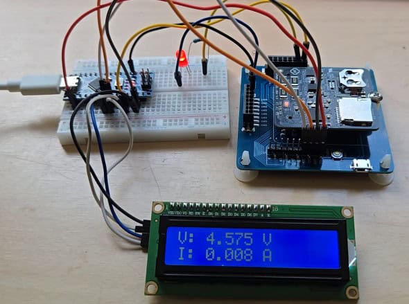
Testing the Arduino DC Energy Meter with LCD
Once you have completed the wiring and uploaded the code to the Arduino, the system is ready for testing.
Make sure that the module is connected to a DC supply and that a load is attached to the selected channel. As soon as the code is running, you will see the measured values of voltage, current, power, and energy displayed directly on the 16×2 I²C LCD screen.
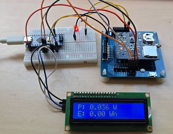
The DC Power Meter Module can measure input voltages in the range of 0 to 32 volts and currents from 0 to 5 amperes. For testing, you can connect a variable DC power supply or a battery as the source, along with a suitable load such as an LED, a resistor, or a small DC motor.
Video Tutorial & Guide

")


