

Introduction
Buck Converter is a dc-to-dc converter designed to perform the step down conversion of applied dc input. In a buck converter, the applied fixed dc input is reduced to a specific dc output voltage i.e. output voltage of the buck converter is always less than the input voltage. So, the Buck converter is also called the step-down converter or step-up chopper.
The efficient power conversion in bulk converter extends battery life and reduces the heat produced. So, it is mostly preferred for the production of smaller gadgets. It can be used in lots of cool applications. It is widely used in SMPS (switched-mode power supply) where the output dc voltage required is less than the input dc voltage.
There are various semiconductor devices like power MOSFET, power BJT, IGBT, and GTO that are used as a switch in buck converter circuits. Thyristors are not used generally for dc-dc converters because another external communication circuit is required when using a thyristor. Whereas power MOSFET or IGBT can be turned off by maintaining zero potential between the gate to the source terminal of power MOSFET, or the gate to the collector terminal of IGBT.
Operating Principle of Buck Converter
The operation of the buck converter is based on the principle of storing energy in an inductor. The voltage drop across an inductor is proportional to the change in the electric current flowing through the device. A switching transistor is used in between input and output for continuous switches on and off at high frequency. To maintain a continuous output, the circuit uses the energy stored in the inductor.
The circuit diagram for a typical buck converter is shown in the figure below.

In this circuit, the input voltage is connected to a controllable solid state device which operates as a switch. In circuit diagram represent that switch which is power MOSFET. There is another switch used in the circuit which is a freewheeling diode (FD). The switch and diode FD are connected to a low pass LC filter in order to reduce the current and voltage ripples which help in generating regulated dc output.
Here, the load is purely resistive load. The input voltage and current through load are constant. And the load can be seen as a current source.
The controlled switch is turned on and off by using PWM (Pulse Width Modulation). PWM can be time-based or frequency based. Time-based Modulation is mostly used for buck converters because it is simple to construct and use. The frequency remains constant in this type of PWM modulation. Whereas Frequency-based modulation has a wide range of frequencies to achieve the desired control of the switch and has a complicated design for the low-pass LC filter.
There are two modes of operation of the Buck converter. They are:
- Mode I: Switch1 is ON and Diode FD is OFF
- Mode II: Switch1 is OFF and Diode FD is ON
Mode I: Switch S1 is ON and Diode FD is OFF

In this mode of operation, switch S1 is in closed condition i.e. ON state, and diode FD is in open condition i.e. OFF state. Thus switch S1 allows the flow of current through it. The circuit diagram for this mode is shown in the above figure.
When a constant dc voltage is applied across the input terminal of the circuit, then the current flow in the circuit through closed switch S1 whereas the diode FD is in reverse biased condition. Due to this current flow in the circuit, the inductor “L” store energy in the form of a magnetic field. The capacitor is connected as shown in the circuit diagram. The current flows through the capacitor also and hence the capacitor store the charge. The voltage across the capacitor appears across the load and is equal to the output voltage Vo.
Let us say the switch S1 is ON for a time Ton and it is OFF for a time Toff.
Then the total time period T is a combination of Ton and Toff time.
![]()
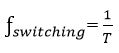
Then the switching frequency is given by:
And the duty cycle is given by:

Applying KVL in the above circuit, we get:
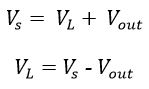
Also, we have:
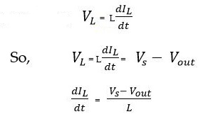
Since switch S1 is on closed condition for a time:
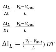
Then,

This equation gives the change in current through the circuit when switch S1 is closed. i.e. in Mode I.
Mode II: Switch S1 is OFF and Diode FD is ON

In this mode of operation, the switch S1 is in open condition i.e. OFF state and diode FD is in closed condition i.e. ON state. Thus switch diode FD allows the flow of current through it, whereas switch S1 blocks the current flow through it. The circuit diagram for this mode is shown in the above figure.
We know that the inductor in the circuit store energy in the form of a magnetic field. When S1 is open, then the inductor acts as the source. Hence diode FD becomes closed. In this mode of operation, the inductor releases the energy stored in the previous mode when switch S1 was closed. During releasing of energy stored in the inductor, the polarity of the inductor gets reversed which causes the freewheeling diode (FD) to come in forward biased condition. So it allows the flow of current in the circuit through diode FD. The way of current flow is shown in the above figure.
The flow of current in the circuit will continue until the stored energy in the inductor gets completely collapsed. When the inductor gets completely discharged, the freewheeling diode (FD) comes in reverse biased condition and hence diode FD will be open. Instantly, the switch S1 will get closed. In this way, the cycle will be continuing.
Now, applying KVL in the above circuit, where we kept the original convention to analyze the circuit, we get:
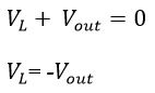
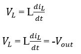
Also we have:
From above, it is known that: T = Ton + Toff
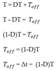
Now,from above equation:
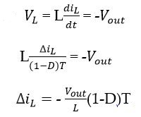
This equation gives the rate of change of current through the inductor when the switch S1 is in the OFF state i.e. in Mode II.
Since the net change in current through the inductor in one complete cycle is zero i.e, the summation of the rate of change of current in Mode I and Mode II becomes zero.
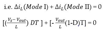
On simplifying, we get:

We know that the value of duty cycle D varies between 0 and 1. For this range of D, the output voltage is lower than the input voltage. Hence in this way buck converter steps down the input voltage.
The waveform of the Buck converter is shown in the figure below:

Applications
Buck converter is basically used for conversion of high dc voltage to low dc voltage. It is mostly used in the following applications:
- It is used in battery power systems such as battery chargers for mobile phones, laptops, and power banks
- It is used in self-regulating power systems such as SMPS
- It is used point of load converters for PCs and motherboards
- It is used in solar chargers
- It is used in adaptive control applications
- It is used in power audio amplifier applications
Some of the DC-to-DC Step Down Buck Converter Module available in market are XL4015, LM2595, XL6009 etc.


