

Overview
In this project, we will create an IoT-based AC Energy Meter using the ESP32 microcontroller and the PZEM-004T module, a high-precision AC power monitoring solution. Unlike traditional Arduino-based setups with LCD displays, this project uses the ESP32’s Wi-Fi capabilities to host a local web server. The Webserver dynamically displays voltage, current, power, energy, frequency, and power factor on a responsive webpage. Data updates in real time without requiring manual page refreshes.
Earlier energy meter projects, such as those using the ZMPT101B voltage sensor and SCT-013 current sensor, are excellent for learning but lack precision. The PZEM-004T addresses this gap with industrial-grade accuracy.
You may take a look at the previous energy meter projects:
- GSM-Based Prepaid Energy Meter
- IoT DC Energy Meter using INA226 & ESP32
- IoT AC Energy Meter with ESP32 & Blynk
- Energy Meter using ESP32 & HMI Display
The PZEM-004T Multifunction AC Digital Meter communicates via Modbus-RTU over RS485, enabling reliable measurement of:
- Voltage (V)
- Current (A)
- Active Power (W)
- Energy (kWh)
- Frequency (Hz)
- Power Factor
In this project, the ESP32 reads data from the PZEM-004T using ModbusMaster library. The ESPAsyncWebServer and AsyncTCP libraries create a non-blocking web server. The webpage uses JavaScript to fetch live data from the ESP32 without reloading, ensuring smooth real-time visualization. By the end, you’ll have a robust IoT energy meter ready for home automation, industrial monitoring, or smart grid applications.
Bill of Materials
We need following components to build this IoT AC Energy Meter project. You can purchase all the components from the given links.
| S.N. | Components Name | Quantity | Purchase Link |
|---|---|---|---|
| 1 | ESP32 Board | 1 | Amazon | AliExpress |
| 2 | PZEM-004T AC Meter Module | 1 | Amazon | AliExpress |
| 3 | Connecting Wires | 10 | Amazon | AliExpress |
| 4 | Breadboard | 1 | Amazon | AliExpress |
PZEM-004T Multifunction AC Digital Meter
The PZEM-004T is a compact, single-phase AC power monitoring module designed to measure electrical parameters such as voltage (80–260V), current (up to 100A via external CT), active power, energy consumption (kWh), frequency, and power factor.

It communicates via Modbus-RTU protocol over TTL serial (), making it easy to interface with microcontrollers like Arduino or ESP32. With built-in galvanic isolation and a non-invasive current transformer, it prioritizes safety. It is widely used in IoT applications, smart metering, and home automation projects.
PZEM-004T V3.0 Feature
- Voltage: 80–260V, 0.1V resolution, 0.5% accuracy
- Current: 0–10A (10A model), 0–100A (100A model), 0.001A resolution, 0.5% accuracy
- Active Power: 0–2.3kW (10A model), 0–23kW (100A model), 0.1W resolution, 0.5% accuracy
- Power Factor: 0.00–1.00, 0.01 resolution, 1% accuracy
- Frequency: 45–65Hz, 0.1Hz resolution, 0.5% accuracy
- Active Energy: 0–9999.99kWh, 1Wh resolution, 0.5% accuracy, resettable via software
- Over Power Alarm: Settable threshold, triggers alarm on exceedance
- Communication: RS485 (UART to RS485), 9600 baud, 8N1
Open CT & Close CT
Both Close CT and Open CT are 100A current transformers (Class 1.5 accuracy) compatible with the PZEM-004T module.

The Closed Current Transformer (CT) version of the PZEM-004T comes with a built-in, non-detachable CT, ensuring accurate and stable measurements. It is ideal for fixed installations where the sensor remains permanently connected to the measured circuit.
The Open Current Transformer (CT) version features a detachable clamp-type CT, allowing easy installation without disconnecting wires. This is useful for retrofitting or temporary monitoring applications where quick and flexible deployment is required.
Pinout of PZEM-004T V3.0
The PZEM-004T is an energy monitoring module that communicates via UART (RS485) and has the following pin configuration:

1. Power & Measurement Pins:
- L (Live) & N (Neutral): Connect to AC mains for voltage measurement and module power.
- CT+ & CT-: Connect to the current transformer (CT) for current measurement.
2. Communication Pins (TTL Serial or RS485):
- 5V: Power supply for the module (external 5V required).
- GND: Ground reference for communication.
- TX (Transmit): Sends data to the microcontroller.
- RX (Receive): Receives data from the microcontroller.
Module TTL Interface Note: This module’s TTL interface is passive and requires an external 5V power supply. All four pins (5V, RX, TX, GND) must be connected for proper communication. Operating temperature range: -20°C to +60°C.
Communication Protocol of PZEM-004T V3.0
1. Physical Layer Protocol
- Uses UART to RS485 communication interface
- Baud rate: 9600, 8 data bits, 1 stop bit, no parity
2. Application Layer Protocol
- Uses Modbus-RTU protocol
- Supported function codes:
- 0x03 (Read Holding Register)
- 0x04 (Read Input Register)
- 0x06 (Write Single Register)
- 0x41 (Calibration – internal use only, requires password 0x3721)
- 0x42 (Reset Energy)
3. Addressing
- Slave address range: 0x01 – 0xF7
- 0x00: Broadcast address (slave does not reply)
- 0xF8: General address (for single-slave environments and calibration)
4. Reading Measurement Results
- Master command format (8 bytes):
Slave Address + 0x04 + Register Address (High + Low) + No. of Registers (High + Low) + CRC (High + Low) - Correct Reply:
Slave Address + 0x04 + No. of Bytes + Register Data + CRC - Error Reply:
Slave Address + 0x84 + Error Code + CRC- 0x01: Illegal function
- 0x02: Illegal address
- 0x03: Illegal data
- 0x04: Slave error
5. Register Mapping
| Register Address | Description | Resolution |
|---|---|---|
| 0x0000 | Voltage | 0.1V |
| 0x0001-0x0002 | Current (Low & High) | 0.001A |
| 0x0003-0x0004 | Power (Low & High) | 0.1W |
| 0x0005-0x0006 | Energy (Low & High) | 1Wh |
| 0x0007 | Frequency | 0.1Hz |
| 0x0008 | Power factor | 0.01 |
| 0x0009 | Alarm status (0xFFFF = Alarm, 0x0000 = No Alarm) |
For example, to read 10 registers from slave address 0x01, the master sends:0x01 + 0x04 + 0x00 + 0x00 + 0x00 + 0x0A + CRC
Indicator Lights of PZEM-004T V3.0
The module has multiple LEDs to indicate power, pulse, and communication status:

- Power Indicator Light: Shows that the module is powered and operational.
- Pulse Indicator Light: It blinks based on active energy measurement. The higher blinking rate indicates higher power consumption.
- TX Communication Light: Blinks when the module transmits data via RS485.
- RX Communication Light: Blinks when the module receives data from the master device (e.g., Arduino, ESP32).
Refer to PZEM-004T Datasheet for more information.
Interfacing PZEM-004T with ESP32 Microcontroller
Lets interface the PZEM-004T AC Energy Meter Module with ESP32 Microcontroller and read the energy meter data. For that, we will first connect the PZEM-004T with ESP32 and then write a C++ Code to fetch the PZEM-004T data.
Circuit Diagram & Connections
The following is the connection diagram between PZEM-004T & ESP32 which looks simple and straightforward.
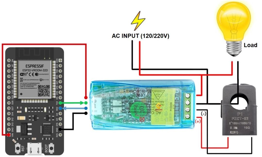
Connect the PZEM-004T’s 5V and GND to ESP32’s 5V and GND for power. Link TX (PZEM) → RX2 (ESP32 pin 16) and RX (PZEM) → TX (ESP32 pin 17) for serial communication.
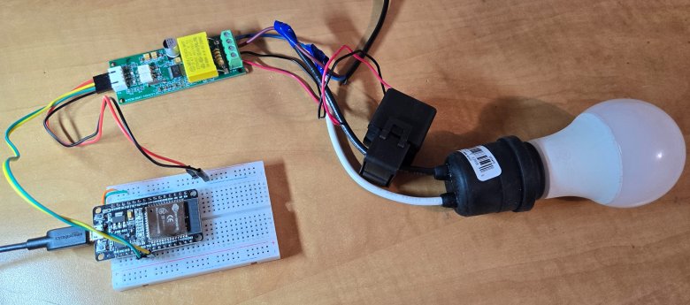
Connect the circuit on breadboard as per circuit diagram above.
Wire the live (L) and neutral (N) of your AC supply (120V/220V) to the PZEM’s AC input terminals (labeled “L” and “N”).
For Open CT (split-core): Clamp the CT around the live wire of the AC circuit you want to monitor (do NOT clamp neutral).
For Close CT (solid-core): Disconnect the circuit, thread the live wire through the CT’s core, and reconnect.
Caution: Isolate AC input (120/220V) wiring from Arduino circuits for safety.
Source Code/Program
Lets write a C++ Code to establish a Serial Communication between ESP32 & PZEM-004T Energy Meter Module. But before moving to the coding part, first install the PZEM-004T Arduino Library. The library is well written and does the Energy monitoring task using the ModBUS interface.
This code reads AC power parameters (voltage, current, power, energy, etc.) from the PZEM-004T sensor using an ESP32 via its Serial2 interface and prints the data to the Serial Monitor every 2 seconds. It includes error handling for failed sensor readings and allows optional energy counter resetting.
|
1 2 3 4 5 6 7 8 9 10 11 12 13 14 15 16 17 18 19 20 21 22 23 24 25 26 27 28 29 30 31 32 33 34 35 36 37 38 39 40 41 42 43 44 45 46 47 48 49 50 51 52 53 54 55 |
#include <PZEM004Tv30.h> // Define the UART2 RX and TX pins on ESP32 (Connect these to PZEM-004T) #define PZEM_RX_PIN 16 // ESP32 RX (Connect to PZEM TX) #define PZEM_TX_PIN 17 // ESP32 TX (Connect to PZEM RX) // Initialize the PZEM sensor using Hardware Serial2 PZEM004Tv30 pzem(Serial2, PZEM_RX_PIN, PZEM_TX_PIN); void setup() { Serial.begin(115200); Serial.println("PZEM-004T V3.0 Power Meter - ESP32"); // Uncomment to reset the energy counter // pzem.resetEnergy(); } void loop() { Serial.print("Custom Address: "); Serial.println(pzem.readAddress(), HEX); // Read data from the PZEM sensor float voltage = pzem.voltage(); float current = pzem.current(); float power = pzem.power(); float energy = pzem.energy(); float frequency = pzem.frequency(); float pf = pzem.pf(); // Original error handling (unchanged) if(isnan(voltage)){ Serial.println("Error reading voltage"); } else if (isnan(current)) { Serial.println("Error reading current"); } else if (isnan(power)) { Serial.println("Error reading power"); } else if (isnan(energy)) { Serial.println("Error reading energy"); } else if (isnan(frequency)) { Serial.println("Error reading frequency"); } else if (isnan(pf)) { Serial.println("Error reading power factor"); } else { // Print values Serial.print("Voltage: "); Serial.print(voltage); Serial.println(" V"); Serial.print("Current: "); Serial.print(current); Serial.println(" A"); Serial.print("Power: "); Serial.print(power); Serial.println(" W"); Serial.print("Energy: "); Serial.print(energy, 3); Serial.println(" kWh"); Serial.print("Frequency: "); Serial.print(frequency); Serial.println(" Hz"); Serial.print("Power Factor: "); Serial.println(pf); } Serial.println(); delay(2000); // Wait 2 seconds before next reading } |
Upload the above code to the ESP32 microcontroller and your device is ready for test.
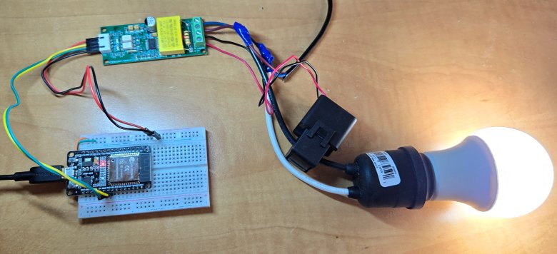
Power on the entire device, load and PZEM-004T Module.
Once powering is done, open the Serial Monitor.
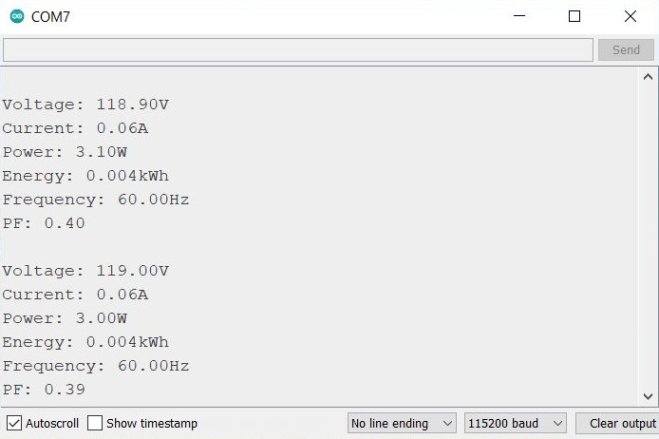
The Serial Monitor will display the value of AC voltage, Current, Power, Energy, Frequency and Power Factor.
IoT AC Energy Meter with PZEM-004T & ESP32 WebServer
The above code worked perfectly and gives the output as expected. Now we can use the data and upload it on Internet to visualize it locally or globally. In this way, we can create an IoT based AC Energy Meter with PZEM-004T & ESP32.
Source Code/Program
We can modify the above code and add HTML, CSS & JavaScript to create a beautiful, responsive and AJAX based webserver. The following code creates an IoT web-based AC energy meter using ESP32 and PZEM-004T, featuring:
Web Interface (HTML/CSS/JS)
- Responsive Dashboard: Uses CSS Grid/Flexbox for a card-based layout that adapts to screen sizes, with Font Awesome icons and color-coded metrics.
- Auto-Refresh UI: JavaScript fetches JSON data via
XMLHttpRequestevery 2 seconds from/dataendpoint, updating values like voltage, current, and power without page reloads (Ajax). - Dynamic Placeholders: HTML uses
%VARIABLE%syntax (e.g.,%VOLTAGE%) replaced by ESP32’sprocessor()function during initial page load.
Backend (ESP32)
- Async Web Server: Hosts a non-blocking server using
ESPAsyncWebServerto handle both the dashboard page (/) and JSON API (/data). - Sensor Integration: Reads PZEM-004T data (voltage, current, etc.) and stores it in global variables, which are atomically updated every 2 seconds.
- Error Handling: Returns “Error” in JSON/UI if sensor readings fail (
isnan()checks).
Copy the following code and paste it on your Arduino IDE editor window.
|
1 2 3 4 5 6 7 8 9 10 11 12 13 14 15 16 17 18 19 20 21 22 23 24 25 26 27 28 29 30 31 32 33 34 35 36 37 38 39 40 41 42 43 44 45 46 47 48 49 50 51 52 53 54 55 56 57 58 59 60 61 62 63 64 65 66 67 68 69 70 71 72 73 74 75 76 77 78 79 80 81 82 83 84 85 86 87 88 89 90 91 92 93 94 95 96 97 98 99 100 101 102 103 104 105 106 107 108 109 110 111 112 113 114 115 116 117 118 119 120 121 122 123 124 125 126 127 128 129 130 131 132 133 134 135 136 137 138 139 140 141 142 143 144 145 146 147 148 149 150 151 152 153 154 155 156 157 158 159 160 161 162 163 164 165 166 167 168 169 170 171 172 173 174 175 176 177 178 179 180 181 182 183 184 185 186 187 188 189 190 191 192 193 194 195 196 197 198 199 200 201 202 203 204 205 206 207 208 209 210 211 212 213 214 215 216 217 218 219 220 221 222 223 224 225 226 227 228 229 230 231 232 233 234 235 236 237 238 239 240 241 |
#include <PZEM004Tv30.h> #include <WiFi.h> #include <ESPAsyncWebServer.h> #include <AsyncTCP.h> // WiFi credentials const char* ssid = "*******************"; const char* password = "*******************"; // PZEM Serial pins #define PZEM_RX_PIN 16 #define PZEM_TX_PIN 17 // Create AsyncWebServer object on port 80 AsyncWebServer server(80); // Initialize PZEM sensor PZEM004Tv30 pzem(Serial2, PZEM_RX_PIN, PZEM_TX_PIN); // Global variables to store sensor data float voltage = 0.0; float current = 0.0; float power = 0.0; float energy = 0.0; float frequency = 0.0; float pf = 0.0; const char index_html[] PROGMEM = R"rawliteral( <!DOCTYPE HTML> <html> <head> <title>ESP32 Power Monitor</title> <meta name="viewport" content="width=device-width, initial-scale=1"> <link rel="stylesheet" href="https://cdnjs.cloudflare.com/ajax/libs/font-awesome/6.0.0/css/all.min.css"> <style> body { font-family: Arial, sans-serif; margin: 0; padding: 20px; background-color: #f0f0f0; } .grid { display: grid; grid-template-columns: repeat(auto-fit, minmax(300px, 1fr)); gap: 20px; max-width: 1200px; margin: 0 auto; } .card { background: white; border-radius: 15px; padding: 25px; box-shadow: 0 4px 8px rgba(0,0,0,0.1); display: flex; align-items: center; text-align: left; } .icon { font-size: 40px; margin-right: 25px; min-width: 50px; text-align: center; } .content { display: flex; flex-direction: column; } .label { font-size: 16px; color: #7f8c8d; margin-bottom: 5px; font-weight: bold; } .value { font-size: 24px; color: #2c3e50; display: flex; align-items: baseline; } .unit { font-size: 16px; color: #95a5a6; margin-left: 5px; } .fa-bolt { color: #f1c40f; } .fa-exchange-alt { color: #3498db; } .fa-plug { color: #e74c3c; } .fa-chart-line { color: #2ecc71; } .fa-wave-square { color: #9b59b6; } .fa-percent { color: #e67e22; } h1 { text-align: center; margin: 30px 0; color: #2c3e50; } </style> <script> function updateData() { var xhttp = new XMLHttpRequest(); xhttp.onreadystatechange = function() { if (this.readyState == 4 && this.status == 200) { var data = JSON.parse(this.responseText); document.getElementById('voltage').innerHTML = data.voltage + '<span class="unit">V</span>'; document.getElementById('current').innerHTML = data.current + '<span class="unit">A</span>'; document.getElementById('power').innerHTML = data.power + '<span class="unit">W</span>'; document.getElementById('energy').innerHTML = data.energy + '<span class="unit">kWh</span>'; document.getElementById('frequency').innerHTML = data.frequency + '<span class="unit">Hz</span>'; document.getElementById('pf').innerHTML = data.pf; } }; xhttp.open("GET", "/data", true); xhttp.send(); } setInterval(updateData, 2000); window.onload = updateData; </script> </head> <body> <h1><i class="fas fa-plug"></i> ESP32 Power Monitor</h1> <div class="grid"> <div class="card"> <i class="fas fa-bolt icon"></i> <div class="content"> <div class="label">VOLTAGE</div> <div class="value" id="voltage">%VOLTAGE%<span class="unit">V</span></div> </div> </div> <div class="card"> <i class="fas fa-exchange-alt icon"></i> <div class="content"> <div class="label">CURRENT</div> <div class="value" id="current">%CURRENT%<span class="unit">A</span></div> </div> </div> <div class="card"> <i class="fas fa-plug icon"></i> <div class="content"> <div class="label">POWER</div> <div class="value" id="power">%POWER%<span class="unit">W</span></div> </div> </div> <div class="card"> <i class="fas fa-chart-line icon"></i> <div class="content"> <div class="label">ENERGY</div> <div class="value" id="energy">%ENERGY%<span class="unit">kWh</span></div> </div> </div> <div class="card"> <i class="fas fa-wave-square icon"></i> <div class="content"> <div class="label">FREQUENCY</div> <div class="value" id="frequency">%FREQUENCY%<span class="unit">Hz</span></div> </div> </div> <div class="card"> <i class="fas fa-percent icon"></i> <div class="content"> <div class="label">POWER FACTOR</div> <div class="value" id="pf">%PF%</div> </div> </div> </div> </body> </html> )rawliteral"; String processor(const String& var) { if(var == "VOLTAGE") return isnan(voltage) ? "Error" : String(voltage, 1); else if(var == "CURRENT") return isnan(current) ? "Error" : String(current, 2); else if(var == "POWER") return isnan(power) ? "Error" : String(power, 1); else if(var == "ENERGY") return isnan(energy) ? "Error" : String(energy, 3); else if(var == "FREQUENCY") return isnan(frequency) ? "Error" : String(frequency, 1); else if(var == "PF") return isnan(pf) ? "Error" : String(pf, 2); return String(); } void setup() { Serial.begin(115200); // Connect to WiFi WiFi.begin(ssid, password); Serial.print("Connecting to WiFi"); while (WiFi.status() != WL_CONNECTED) { delay(500); Serial.print("."); } Serial.println("\nConnected to WiFi"); Serial.print("IP Address: "); Serial.println(WiFi.localIP()); // Route for root / web page server.on("/", HTTP_GET, [](AsyncWebServerRequest *request){ request->send_P(200, "text/html", index_html, processor); }); // Route for JSON data server.on("/data", HTTP_GET, [](AsyncWebServerRequest *request){ String json = "{"; json += "\"voltage\":\"" + String(isnan(voltage) ? "Error" : String(voltage, 1)) + "\","; json += "\"current\":\"" + String(isnan(current) ? "Error" : String(current, 2)) + "\","; json += "\"power\":\"" + String(isnan(power) ? "Error" : String(power, 1)) + "\","; json += "\"energy\":\"" + String(isnan(energy) ? "Error" : String(energy, 3)) + "\","; json += "\"frequency\":\"" + String(isnan(frequency) ? "Error" : String(frequency, 1)) + "\","; json += "\"pf\":\"" + String(isnan(pf) ? "Error" : String(pf, 2)) + "\""; json += "}"; request->send(200, "application/json", json); }); // Start server server.begin(); } void loop() { // Read all values first float v = pzem.voltage(); float c = pzem.current(); float p = pzem.power(); float e = pzem.energy(); float f = pzem.frequency(); float pf_val = pzem.pf(); // Update global variables atomically voltage = v; current = c; power = p; energy = e; frequency = f; pf = pf_val; // Serial output Serial.print("Voltage: "); Serial.print(voltage); Serial.println("V"); Serial.print("Current: "); Serial.print(current); Serial.println("A"); Serial.print("Power: "); Serial.print(power); Serial.println("W"); Serial.print("Energy: "); Serial.print(energy,3); Serial.println("kWh"); Serial.print("Frequency: "); Serial.print(frequency); Serial.println("Hz"); Serial.print("PF: "); Serial.println(pf); Serial.println("-------------------"); delay(2000); } |
From the above code, you need to change the Wi-Fi SSID and password. Replace it with your network credentials.
|
1 2 3 |
// WiFi credentials const char* ssid = "*******************"; const char* password = "*******************"; |
Finally, after making the changes you can upload the code to the ESP32 microcontroller.
Testing the IoT Energy Meter
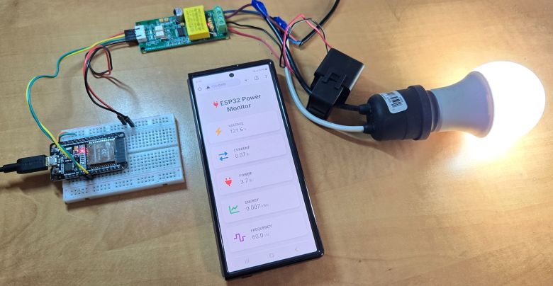
After core uploading is done, wire the PZEM-004T to the AC mains (e.g., a power strip or appliance) for live measurements. Now the system is ready for test.
Open the Arduino IDE Serial Monitor (115200 baud).
The ESP32 will try connecting to the WiFi network using the given credentials. If connection is successful, it will show WiFi connection success, and the IP address is printed.
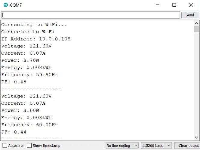
The Serial Monitor shows PZEM-004T data (voltage, current, power, energy, frequency, power factor) which is updated every 2 seconds. Ensure that No “Error” messages are in readings.
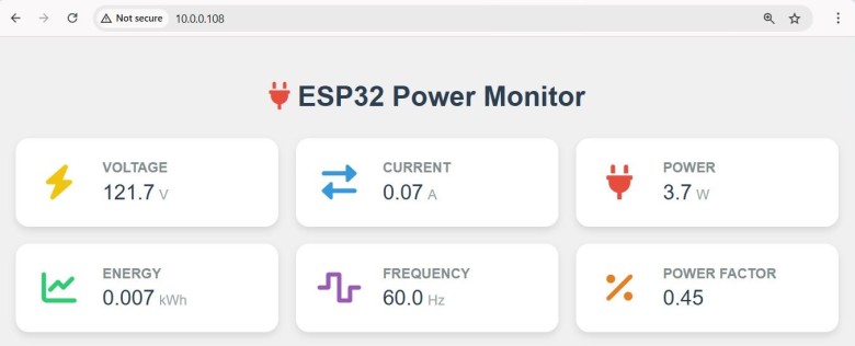
On any device (phone/PC), connect to the same WiFi network as the ESP32. Open a browser and enter the ESP32’s IP address (from Serial Monitor). From the computer dashboard, the web page appears as this:
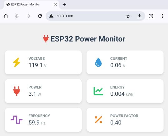
You may open the same IP address link on your mobile phone. It will display the same energy meter parameters.
The expected result is a polished dashboard with real-time AC parameters (e.g., Voltage: 230V, Current: 0.5A). The values auto-update every 2 seconds without page refresh (Ajax).
You may run the system for 24+ hours to check stability and memory leaks. Also disconnect/reconnect WiFi to verify automatic reconnection. Try to test dashboard access from external networks.
Uncomment pzem.resetEnergy() in setup() to reset kWh counter.
If all steps work, your IoT energy meter is ready for deployment!
 & Live Dashboard")


2 Comments
It appears to me that the photograph of the PZEM etc has the live wire connected to the wrong terminal on the PZEM. Am I interpreting the picture correctly?
It’s AC mains. Makes no difference to the PZEM.