
")
Overview
In this project, we will build our own Wireless IoT Based DC Power Energy Meter using ESP8266 & INA226 Current Sensor. This energy meter is capable of measuring DC Source Voltage, Load Voltage, Current, Power, and Energy Consumption. We can monitor the data online on Blynk Application. The maximum voltage and current this energy meter can measure are 26V and 30A respectively.
Earlier we build IoT AC Energy Meter using ESP32 which could measure voltage, current, and power parameters. But the device is only made for measuring AC parameters. The DC Energy meter requires DC related sensors. To measure DC parameters, we need DC Current/Voltage Sensors. The INA226 is the best choice for these meters as it can measure DC Voltage up to 36V. By adjusting the Shunt resistance on INA226, the maximum current it can measure is 30A.

An IoT DC Power Energy Meter can transmit the sensor data to a central system or application using Internet of Things (IoT) technology. Such meters can provide valuable data in real time about power usage, which can be used to monitor and manage energy consumption more effectively, identify inefficiencies, or automate certain power-related processes.
Bill of Materials
For the IoT DC Power Energy Meter, we need the following components. The components are mostly SMD type with 0805 packages for resistor, capacitor, and LED.
| S.N. | Components | Designator | Footprint | Quantity | Part Number |
|---|---|---|---|---|---|
| 1 | ESP8266-12E | U1 | WIFIM-SMD_ESP-12E | 1 | ESP-12E |
| 2 | LM7805 5V Regulator | U2 | TO-220-3 | 1 | LM7805 |
| 3 | INA226 | U3 | 1x8 2.54MM | 1 | INA226 |
| 4 | HT7333 LDO | U4 | SOT-89-3 | 1 | HT7333-7 |
| 5 | Resistor 220E | R9 | R0805 | 1 | |
| 6 | Resistor 330 | R6 | R0805 | 1 | |
| 7 | Resistor 12K | R1,R2,R3,R4,R5 | R0805 | 5 | |
| 8 | Resistor 22K | R7,R8 | R0805 | 2 | |
| 9 | Capacitor 0.1uF | C1 | C0805 | 1 | |
| 10 | Capacitor 470pF | C2 | C0805 | 1 | |
| 11 | Capacitor 10uF | C3,C4 | C0805 | 2 | |
| 12 | Capacitor 47uF, 10V | C6 | CAP-TH_BD6.3-P2.50-D0.5-FD | 1 | |
| 13 | Capacitor 220uF, 50V | C5 | CAP-TH_BD8.0-P3.50-D0.6-FD | 1 | |
| 14 | LED Red | LED1 | LED0805 | 1 | |
| 15 | Transistor BC847 | Q1,Q2 | SOT-23-3 | 2 | BC847A |
| 16 | Push Button | FLS,RST | SW-SMD_L4.0-W3.0-LS4.8 | 2 | TS-1071AS-A1B3-D4 |
| 17 | Slide Switch | SW1 | SW-TH_MK-12D18-G040 | 1 | MK-12D18-G020 |
| 18 | Header Pins 1x6 | PROG | Male Header 1x6 2.54mm | 1 | |
| 19 | Header Pins (1x4) | U5 | Female Header 1x4 2.54mm | 1 | |
| 20 | Terminal Block (1x2) | LOAD, BAT. | TERMINAL_BLOCK_2P_5 | 2 |
INA226 DC Current Sensor
The INA226 is an advanced, high-side current shunt and power monitor IC developed by Texas Instruments. It operates over an I2C-compatible or SMBus-compatible interface, offering direct digital communication with a microcontroller.

It provides more extensive capabilities than the INA219, including better accuracy, more extensive voltage, and current range, as well as integrated math functions that directly report power in watts. The INA226 module is built with an INA226 chip, a few resistors, and a capacitor that helps reduce noise, or unwanted electrical signals.

Features & Specifications of INA226
- Operational Voltage: 2.7 – 5.5 Volts
- Bus Voltage Range: 0 – 36 Volts
- Current Sensing Range: ± 500mA to ± 50A
- Power consumption: Continuous mode: 0.35 mA; Power-Down Mode: 2.3.µA
- Measurement modes:: continuous or on-demand (“triggered”)
- Averaging of 1, 4, 64, 128, 256, 512 or 1024 individual measurements
- A/D conversion time is adjustable in eight levels: 0.14 to 8.2 ms
Current Sensing Resistor Selection
The maximum current that the INA226 can measure is not determined directly by the chip itself, but rather by the value of the shunt resistor used in conjunction with it.
The INA226 measures the voltage drop across a shunt resistor, and from that calculates the current using Ohm’s law (I = V/R). Since the INA226 can measure a maximum shunt voltage of 81.92mV (with a resolution of 2.5µV), the maximum current is dependent on the resistance of the shunt.
Below is a table of suggested shunts.
| Shunt Resistance | Max Current (A) | Part Size | Part Number | Power Rating (W) | Max Power (W) |
| 0.003 | 27.31 | 2512 | ERJMS4SF3M0U | 3 | 2.24 |
| 0.004 | 20.48 | 2512 | ERJMS4SF4M0U | 3 | 1.68 |
| 0.005 | 16.38 | 2512 | ERJMS4HF5M0U | 3 | 1.34 |
| 0.006 | 13.65 | 2512 | ERJMS4HF6M0U | 3 | 1.12 |
| 0.007 | 11.70 | 2512 | ERJMS4HF7M0U | 2 | 0.96 |
| 0.008 | 10.24 | 2512 | ERJMS4HF8M0U | 2 | 0.84 |
| 0.009 | 9.10 | 2512 | ERJMS4HF9M0U | 2 | 0.75 |
| 0.010 | 8.19 | 2512 | ERJMS4HF10MU | 2 | 0.67 |
To learn in detail about the INA226 Current Sensor, we already published a dedicated detailed article. You can follow this article for more information:
Designing of IoT DC Power Energy Meter
Let us take a look at the circuit for IoT DC Power Energy Meter using ESP8266 & INA226. We could have used INA219 Current Sensor for this project, but INA226 has voltage limitations of 26V and the maximum current it can measure is ±3.2A.
We need an energy meter that can measure more voltage and current. The INA226 is the best alternative considering the cost and accuracy. We can measure the voltage up to 36V and the current up to 30A. The current setting is based on the shunt resistance that needs to be selected based on the above table.
Since the device is IoT Based, we used ESP8266 raw chip for this purpose. The entire device is powered using an external power source. Here is the complete schematic for the project.
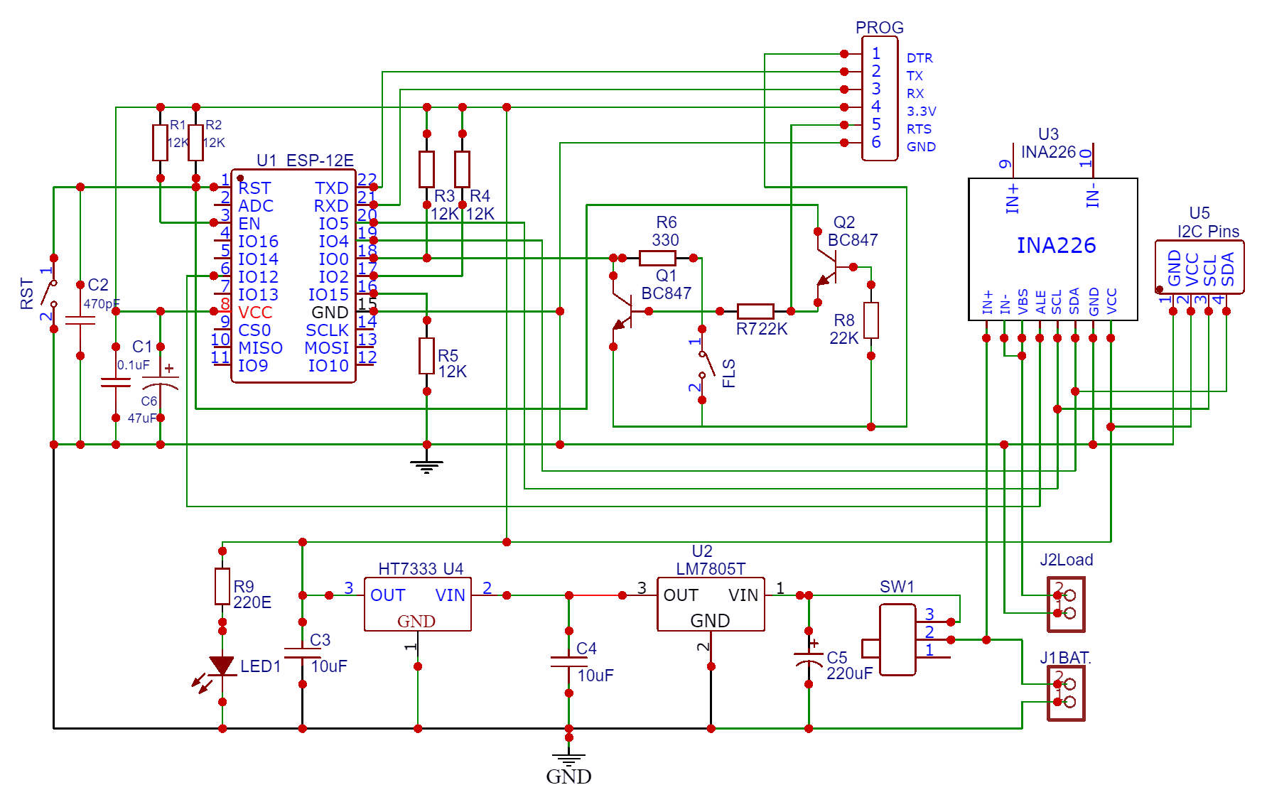
The external DC source such as Battery or a Solar Panel is used to power the circuit. The input voltage should be between 7V to 36V only. The Switch SW1 is used to power on/off the circuit. The Input voltage is fed to the 7805 Voltage regulator IC. Use a proper heat sink for 7805 if the supply voltage is greater than 12V. The capacitor C5 (220uF, 50V) filters input voltages and makes stability. The LM7805 IC outputs 5V DC which is fed to LDO HT7333. The HT7333 limits the voltage to 3.3V. The entire circuit operates at 3.3V. The LED1 indicates whether the circuit is powered on or off.
Moving to the ESP8266 chip part, we have used our ESP8266 Automatic Programmer Circuit. There is no need to press the reset or boot button while uploading the code. You can connect USB-to-TTL Converter Module to PROG Pins & program the circuit. The programming process is automatic and handled by two switches (FLS and RST), two BC547 transistors (Q1 and Q2), and a few other components.

The RTS signal resets the ESP8266, while the DTR signal puts it in flash mode, with Q1 and Q2 preventing the chip’s reset when both signals are low. Upon detecting an upload command, the ESP module auto-switches to flash mode for seamless sketch uploading. In the absence of an upload command, ESP-12E/F starts in normal mode.
For the INA226 Current sensor, the SDA and SCL pins are connected to the SDA & SCL pins of the ESP8266 Chip. The Vin+ pin should be connected to a power source and the Vin- to the load as shown in the design schematic. The INA226 Sensor has VBus Pin, which is used to measure the Load Voltage. Therefore we need to connect the VBus pin to Vin- pin.
The U5 part in the circuit is the I2C and Power pins. You can directly connect a 0.96″ I2C OLED Display here or a 3.3V LCD Display.
Project PCB Design, Gerber File & PCB Ordering Online
The above schematic is designed using EasyEDA. You can convert the schematic to the PCB.
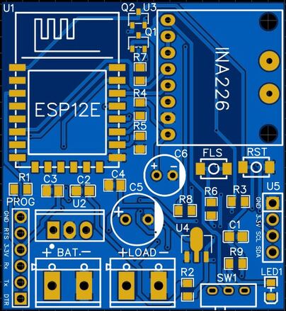
The PCB has SMD components with resistors, capacitors, and LED with an SMD package of 0805. The transistors, and push buttons are also in the SMD package. The front side of the PCB has all the components to be mounted.
The Gerber File for the PCB is given below. You can simply download the Gerber File and order the PCB from ALLPCB at 1$ only.

You can now upload the Gerber File by choosing the Quote Now option. From these options, you can choose the Material Type, Dimensions, Quantity, Thickness, Solder Mask Color and other required parameters.

After filling in all details, select your country and shipping method. Finally, you can place the order.
PCB & Hardware Assembly
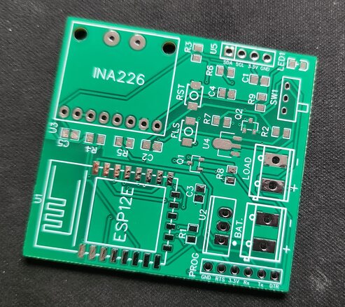
After ordering the PCB, it took almost 5 days and I got my PCB.

The PCB quality from ALLPCB is superb with very high quality. That is why most people trust ALLPCB for PCB/PCBA Services.
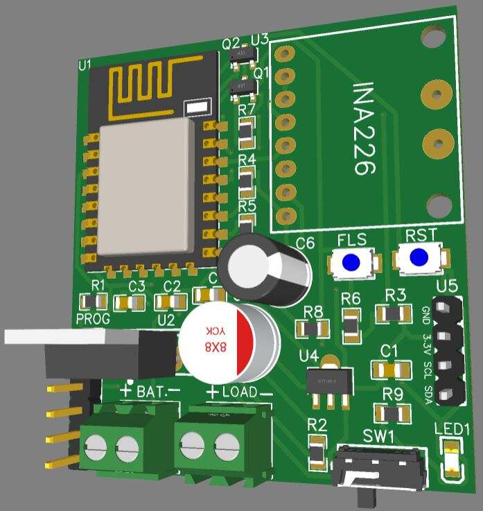
On the front side, first solder all the SMD components like resistors, capacitors, transistors, LED & push buttons. Be careful about the SMD LED polarity, place it in the proper direction. After soldering all these, you can solder the ESP8266 raw chip. The final stage would be soldering all the through-hole components like Switch, terminal block, male-female headers, and INA226 Sensor

After soldering all the components, the IoT Energy Power Meter Board is ready for the test. You can upload a blink sketch by connecting a USB-to-TTL Converter Module.
Note: There were some voltage fluctuation issues in the designed PCB, so I have updated the design by adding some large capacitors. Also, some connection issues have been fixed. The Gerber file above is updated and the PCB would look something like this.
Setting Up Blynk Application
In order to check the Energy Meter data wirelessly and monitor it online, we need an IoT Server with the dashboard. The Blynk App is perfect for our application.
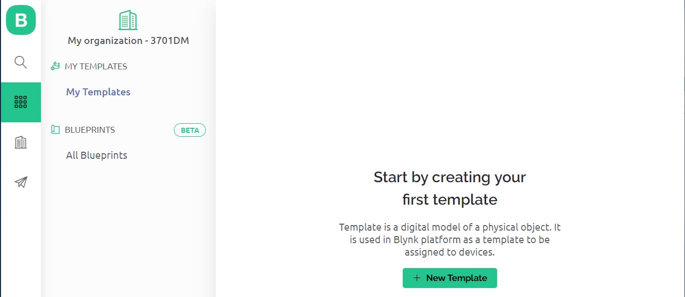
Visit blynk.cloud and create a Blynk account on the Blynk website. Or you can simply sign in using the registered Email ID.
Click on +New Template.
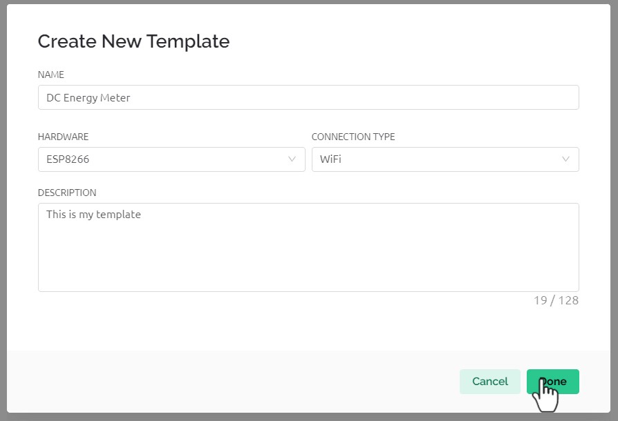
Give any name to the Hardware such as “IoT DC Energy Meter“. Choose the Hardware type as ESP8266 and the connection type as WiFi.
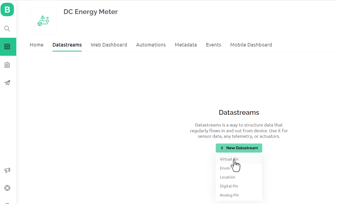
Now we need to set up Datastreams. Therefore Click on +New Datastreams and Select Virtual Pin.
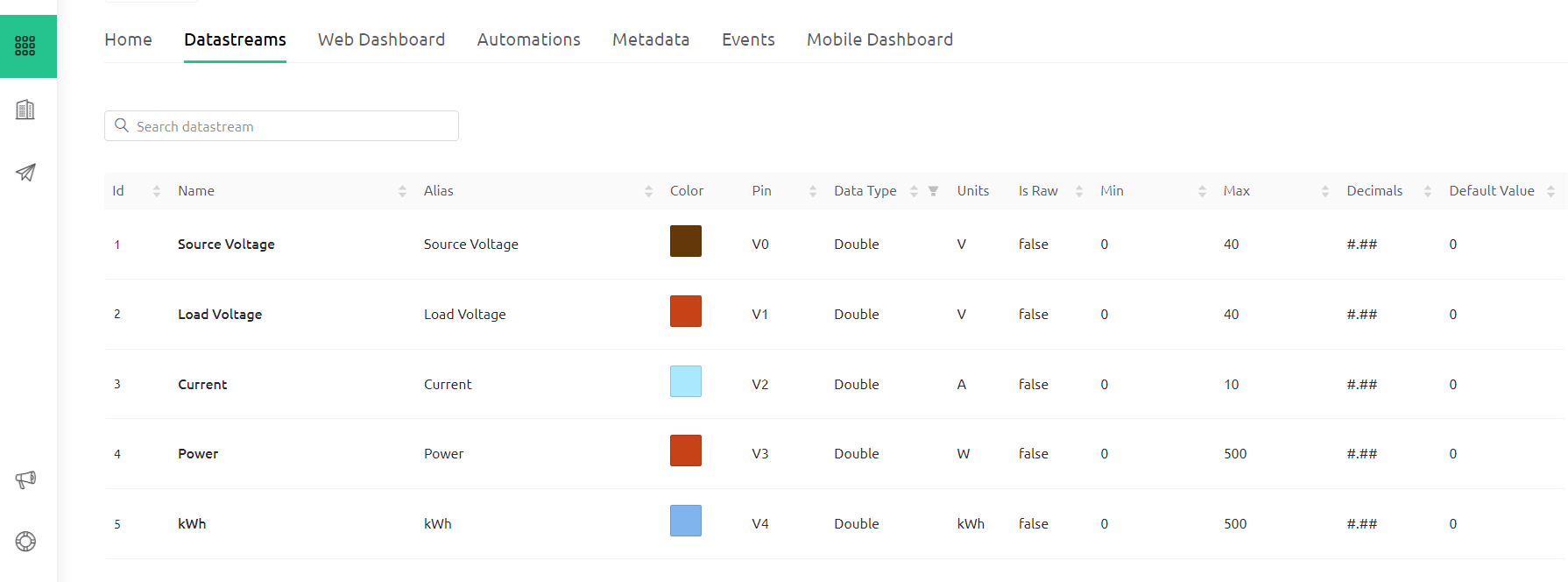
Create datastreams for Source Voltage, Load Voltage, Current, Power, and kWh and assign the virtual pins as V0, V1, V2, V3, and V4 respectively.
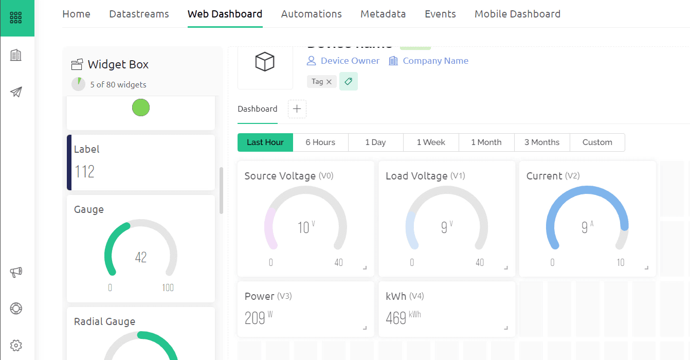
Now go to the Dashboard section and set up the dashboard. For Source Voltage, Load Voltage, and Current, I used the Gauge widget. For Power and kWh, I used a Label display. Link all the widgets with the datastreams and click on save.
Go to the Home and click on Add Device. Name the Device as “DC Energy Meter” and Click on Create.
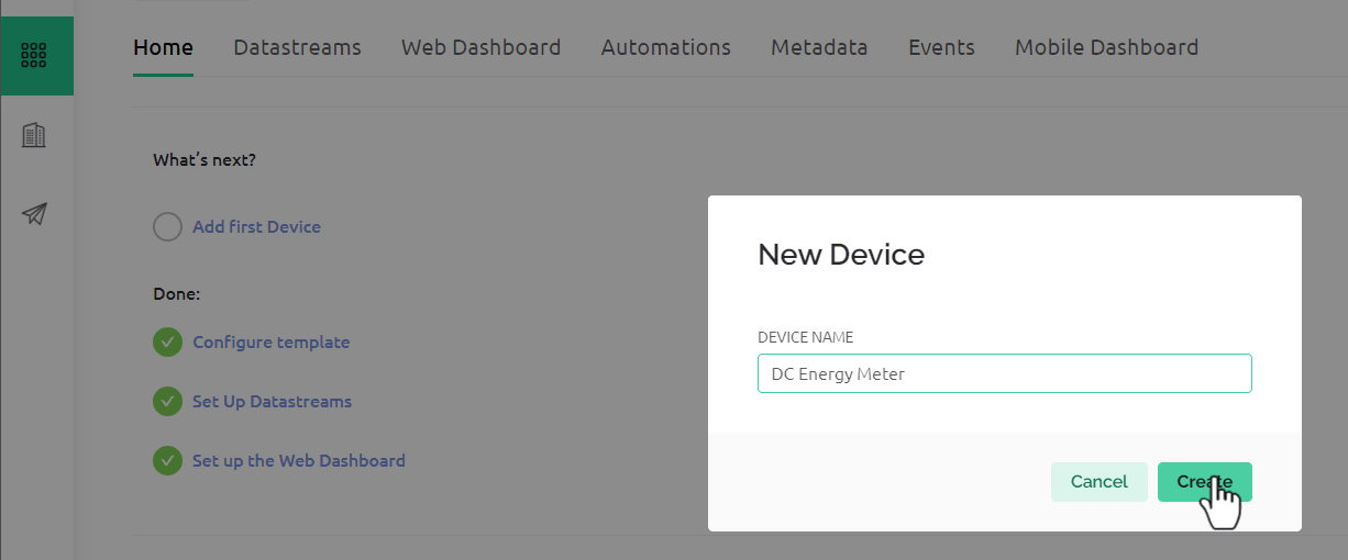
After the device is successfully created, you will get the device ID and Authentication Token. This parameter will be used in the code.
Source Code/Program for IoT DC Energy Meter
After the hardware and Blynk Setup is done, we need to move to the coding part. The IoT DC Energy Power Meter requires ESP8266 firmware for reading INA226 Data and sending it to Blynk Server.
Before moving to the coding part add the following libraries to the Arduino IDE, using the library manager.
From the following lines of the code change the WiFi SSID, Password, Blynk Authentication Token, and Template ID.
|
1 2 3 4 5 |
#define BLYNK_TEMPLATE_ID "************" #define BLYNK_TEMPLATE_NAME "DC Energy Meter" char auth[] = "************"; char ssid[] = "************"; char pass[] = "************"; |
Here is the complete code for this project.
|
1 2 3 4 5 6 7 8 9 10 11 12 13 14 15 16 17 18 19 20 21 22 23 24 25 26 27 28 29 30 31 32 33 34 35 36 37 38 39 40 41 42 43 44 45 46 47 48 49 50 51 52 53 54 55 56 57 58 59 60 61 62 63 64 65 66 67 68 69 70 71 72 73 74 75 76 77 78 79 80 81 82 83 84 85 86 87 88 89 90 91 92 93 94 95 96 97 98 99 100 101 102 103 104 105 106 107 108 109 110 111 112 113 114 115 116 117 118 119 120 121 122 123 124 125 126 127 128 129 130 131 132 133 134 135 136 137 138 139 140 141 142 143 |
#define BLYNK_PRINT Serial #include <Wire.h> #include <INA226_WE.h> //https://github.com/wollewald/INA226_WE #include <ESP8266WiFi.h> #include <WiFiClient.h> #include <BlynkSimpleEsp8266.h> #define BLYNK_TEMPLATE_ID "************" #define BLYNK_TEMPLATE_NAME "DC Energy Meter" char auth[] = "************"; char ssid[] = "************"; char pass[] = "************"; #define I2C_ADDRESS 0x40 INA226_WE ina226 = INA226_WE(I2C_ADDRESS); float shuntVoltage_mV = 0.0; float Load_Voltage = 0.0; float Source_Voltage = 0.0; float Current = 0.0; float Power = 0.0; float kWh = 0; unsigned long lastmillis = millis(); void setup() { Serial.begin(115200); Blynk.begin(auth, ssid, pass); // Start Blynk delay(1000); // wait for a second while (!Serial); // wait until serial comes up on Arduino Leonardo or MKR WiFi 1010 Wire.begin(); ina226.init(); /* Set Number of measurements for shunt and bus voltage which shall be averaged Mode * * Number of samples AVERAGE_1 1 (default) AVERAGE_4 4 AVERAGE_16 16 AVERAGE_64 64 AVERAGE_128 128 AVERAGE_256 256 AVERAGE_512 512 AVERAGE_1024 1024*/ //ina226.setAverage(AVERAGE_16); // choose mode and uncomment for change of default /* Set conversion time in microseconds One set of shunt and bus voltage conversion will take: number of samples to be averaged x conversion time x 2 Mode * * conversion time CONV_TIME_140 140 µs CONV_TIME_204 204 µs CONV_TIME_332 332 µs CONV_TIME_588 588 µs CONV_TIME_1100 1.1 ms (default) CONV_TIME_2116 2.116 ms CONV_TIME_4156 4.156 ms CONV_TIME_8244 8.244 ms */ //ina226.setConversionTime(CONV_TIME_1100); //choose conversion time and uncomment for change of default /* Set measure mode POWER_DOWN - INA226 switched off TRIGGERED - measurement on demand CONTINUOUS - continuous measurements (default)*/ //ina226.setMeasureMode(CONTINUOUS); // choose mode and uncomment for change of default /* Set Resistor and Current Range if resistor is 5.0 mOhm, current range is up to 10.0 A default is 100 mOhm and about 1.3 A*/ ina226.setResistorRange(0.1, 1.3); // choose resistor 0.1 Ohm and gain range up to 1.3A /* If the current values delivered by the INA226 differ by a constant factor from values obtained with calibrated equipment you can define a correction factor. Correction factor = current delivered from calibrated equipment / current delivered by INA226*/ ina226.setCorrectionFactor(0.93); Serial.println("INA226 Current Sensor Example Sketch - Continuous"); ina226.waitUntilConversionCompleted(); //if you comment this line the first data might be zero } void loop() { Blynk.run(); // Initiates Blynk ina226.readAndClearFlags(); shuntVoltage_mV = ina226.getShuntVoltage_mV(); Source_Voltage = ina226.getBusVoltage_V(); Current = ina226.getCurrent_mA() / 1000; Power = ina226.getBusPower() / 1000; Load_Voltage = Source_Voltage + (shuntVoltage_mV / 1000); kWh = kWh + Power * (millis() - lastmillis) / 3600000000.0; //Serial.print("Shunt Voltage [mV]: "); //Serial.println(shuntVoltage_mV); Serial.print("Source Voltage: "); Serial.print(Source_Voltage); Serial.println("V"); Serial.print("Load Voltage:"); Serial.print(Load_Voltage); Serial.println("V"); Serial.print("Current: "); Serial.print(Current); Serial.println("A"); Serial.print("Power: "); Serial.print(Power); Serial.println("W"); Serial.print("kWh: "); Serial.print(kWh); Serial.println("kWh"); if (!ina226.overflow) { Serial.println("Values OK - no overflow"); } else { Serial.println("Overflow! Choose higher current range"); } Serial.println(); //Send to Blynk Blynk.virtualWrite(V0, Source_Voltage); Blynk.virtualWrite(V1, Load_Voltage); Blynk.virtualWrite(V2, Current); Blynk.virtualWrite(V3, Power); Blynk.virtualWrite(V4, kWh); delay(3000); } |
From this code, you need to make some modifications in order to get the result accurately.
|
1 |
ina226.setResistorRange(0.1, 1.3); |
This line set Resistor and Current Range. If the resistor is 5.0 mOhm, the current range is up to 10A. By default is 100 mOhm and about 1.3A. Refer to the table above in the INA226 section to find out the suitable shunt resistor value for your requirements.
|
1 |
ina226.setCorrectionFactor(0.93); |
If the current values delivered by the INA226 differ by a constant factor from values obtained with calibrated equipment you can define a correction factor.
Testing the Hardware
To test whether you are able to upload the code to the ESP8266 Chip or not, connect a USB-to-TTL Converter Module (FTDI) to the Board using the pins mentioned in the PCB. Make sure to connect the RTS pin from the side of the USB-to-TTL Module as well.

Connect the FTDI Board to your computer. From the Board list Select “Generic ESP8266” Board and also select the COM port.

Now hit the upload button to upload the code. After successful code uploading, open the Serial Monitor.
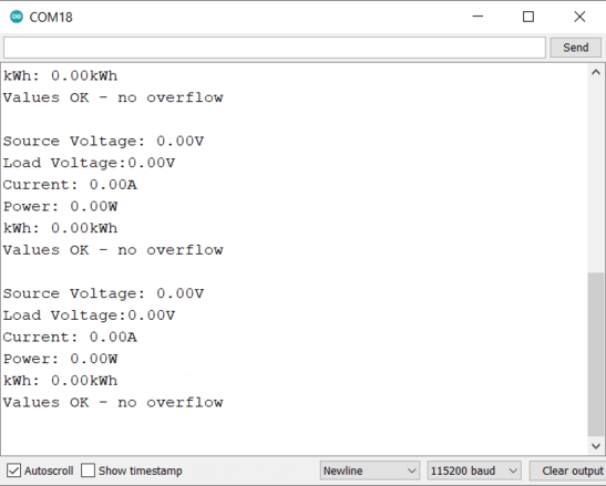
The Serial Monitor will show all the values zero as no source and no load is connected to the Board.
IoT DC Energy Meter Demonstration & Working
In order to test the working, we need to connect a DC Source to the board. The minimum voltage it requires is 7V and the maximum it can withstand is 36V. You can either use a Solar Panel or a 12V Battery.
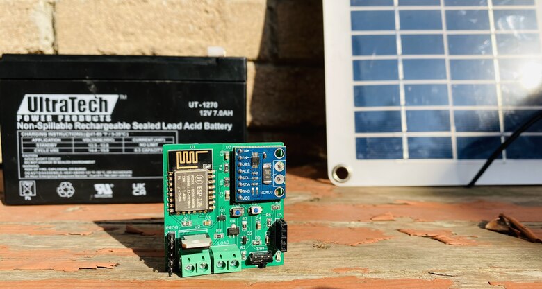
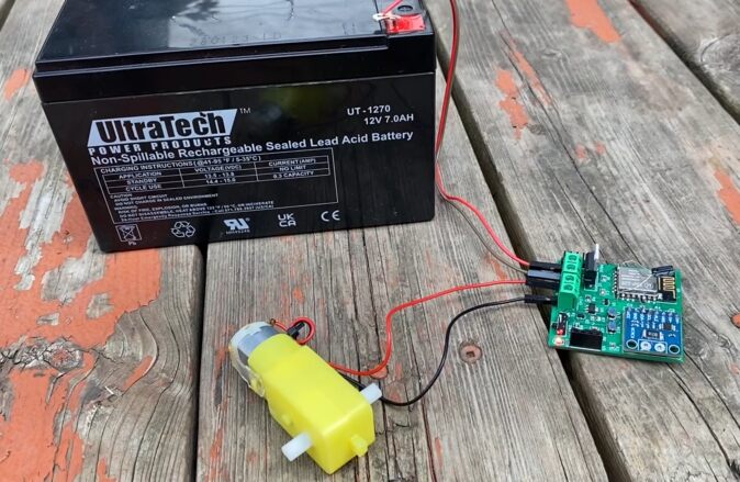
First, connect a 12V Battery to the Battery Terminal of the Board.

In the Load part, you can connect any Load like a 12V LED Light or a DC Motor. For the demo, I used a DC Motor.
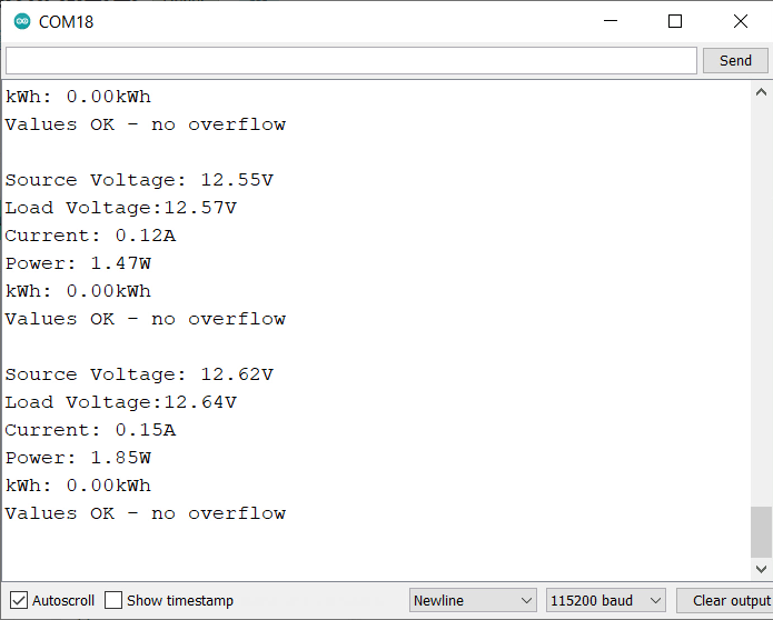
If you check your Serial Monitor, you will observe the values of Source Voltage, Load Voltage, Current, Power, and kWh.
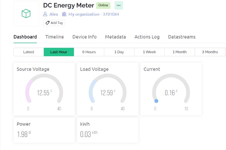
Go to your Blynk Dashboard, you will be able to observe the values online as well.
You may connect multiple loads and increase the power to observe the changes in reading.
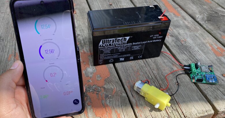
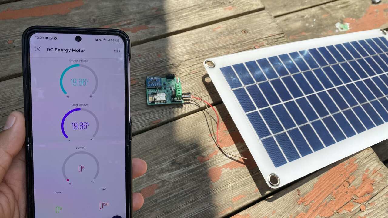
If you have set up the Mobile Blynk Dashboard, you may observe your energy meter readings there.
The same IoT DC Energy Meter based on INA226 & ESP8266 can also be used in Solar Power Monitoring System. For that, connect the Solar panel to the input source and observe the reading in Blynk App.
Thus, this INA226 ESP8266 Based IoT Power Energy Meter can be used in various applications projects.
Video Tutorial & Guide

Conclusion
In conclusion, we successfully created a Wireless IoT Based DC Power Energy Meter using ESP8266 & INA226 Current Sensor. This device demonstrated the capability of measuring DC Source Voltage, Load Voltage, Current, Power, and Energy Consumption and allowing these measurements to be monitored online via the Blynk Application.
The project also showcased the power of IoT in energy management, with real-time data being transmitted to a centralized system. Through this, we can effectively monitor power usage, uncover any inefficiencies, and even automate certain power-related processes. Overall, this project represents a major step forward in the quest for comprehensive, efficient, and automated energy management and serves as a strong foundation for future IoT-based energy monitoring projects.
 & Live Dashboard")


1 Comment
Thanks for this amazing tutorial. I’d appreciate it if you could help guide me on how to set up for 5000 watts dc inverter