

Overview
In this post, we will learn to Design our own ESP Based Board for Battery-Powered IoT Applications. The ESP Controllers from Espressif are popular these days for IoT-based designs. The most popular ESP Boards are ESP8266-01 & ESP8266-12E/12F. These boards are the very popular amount makers, designers & IoT enthusiasts. The ready-made plug and play board is already available in the market. But the problem with these boards is they are very big in size and has power-hungry voltage regulators that may not be suitable for compact and low power projects.
This is why it is necessary to design your own ESP Board for Battery-Powered IoT Applications. In this article, we will learn how to design a circuit and a compact PCB for using the ESP8266 controller. We will use the low-power LDO instead of voltage regulators & add some battery charging and battery management feature to the board.
We will not use any USB-to-UART chip like CP2102, rather we will program the device using external FTDI. By removing the extra chips and using the low-power LDOs will reduce the power consumption and makes the device small-sized. Thus the device can operate with a small Lithium-Ion Battery and charge either using USB or Solar Power. You can also use ESP8285 as an alternative and most of the points discussed here will still be the same.
You can also refer to some earlier articles like ESP8266 Power Supply & also Programming Raw ESP8266 Chip to collect some datas and information before proceeding. In case you want to make Battery Powered ESP32 Board, you can follow the dedicated article.
Bill of Materials
To design your own ESP Board for Battery Powered IoT Applications, we need following components.
| S.N. | Components | Designator | Footprint | Quantity |
|---|---|---|---|---|
| 1 | ESP-12E | U1 | WIFIM-SMD_ESP-12E | 1 |
| 2 | MCP73831 | U3 | SOT-23-5 | 1 |
| 3 | OLED Display | OLED | 0.96 OLED | 2 |
| 4 | LDO HT7333 | U4 | SOT-89-3 | 3 |
| 5 | Header Female-2.54_2x3 | H1 | HDR-TH_6P-P2.54 | 1 |
| 6 | Header Male-2.54_2x3 | GPIO,PROG | HDR-TH_6P-P2.54 | 2 |
| 7 | Reset Switch | FLS,RST | SWITCH SMD 3X4X2MM | 2 |
| 8 | ON/OFF Switch | SW1 | MINI TOGGLE (1P2T) SPDT SLIDE SWITCH | 1 |
| 9 | Micro USB Female | USB1 | MICRO-USB-SMD_5P | 1 |
| 10 | Battery Connector | CN1 | 2 PIN JST | 1 |
| 11 | LED | LED2 | LED-0805 | 1 |
| 12 | Transistor BC547 | Q1,Q2 | SOT23 | 2 |
| 13 | Resistor 330E | R6 | R0805 | 1 |
| 14 | Resistor 15K | R11 | R0805 | 1 |
| 15 | Resistor 2K | R10 | R805 | 1 |
| 16 | Resistor 47K | R12 | R0805 | 1 |
| 17 | Resistor 12K | R1,R2,R3,R4,R5 | R0805 | 5 |
| 18 | Resistor 470E | R9 | R805 | 1 |
| 19 | Resistor 22K | R7,R8 | R0805 | 2 |
| 20 | Capacitor 10uF | C3,C4 | C0805 | 2 |
| 21 | Capacitor 0.1uF | C1 | C0805 | 1 |
| 22 | Capacitor 470pF | C2 | C0805 | 1 |
| 23 | Capacitor 4.7uF | C5,C6 | C0805 | 2 |
| 24 | Battery 3.7V, 500mAh | 1 | ||
| 25 | FTDI Module | 1 | ||
| 26 | Jumper Wires (M-to-F) | 6 |
Circuit Design & Schematic
Here is the ESP8266 Schematic that can be powered by Battery. We are using the raw ESP8266 Chip, which is an ESP8266-12E/12F Chip. The board consists of low-power LDO, battery Management IC, USB for Battery Charging & switch for turning ON/OFF. The rest of the things is explained in detail.

About ESP8266-12E/12F Chip
ESP-12E is a miniature Wi-Fi module present in the market and is used for establishing a wireless network connection for a microcontroller or processor. The core of ESP-12E is ESP8266EX, which is a high integration wireless SoC (System on Chip). It features the ability to embed Wi-Fi capabilities to systems or to function as a standalone application. It is a low-cost solution for developing IoT applications.

ESP8266-12F is an enhanced version of ESP8266-12E that has improved peripheral circuit, enhanced impedance matching, the signal output is better, stable with anti-jamming ability.
- Frequency Range: 2.412 – 2.484 GHz
- Serial Transmission: 110 – 921600 bps, TCP Client 5
- SDIO 2.0, SPI, and UART Interface available
- PWM available
- One ADC channel is available
- Programmable GPIO available
- Wireless Network Type: STA / AP / STA + AP
- Security Type: WEP / WPA-PSK / WPA2-PSK
- Encryption Type: WEP64 / WEP128 / TKIP / AES
- Network Protocol: IPv4, TCP / UDP / FTP / HTTP
- Operating Voltage: 3.3V
- Maximum current allowed to draw per pin: 15mA
- Power down leakage current of < 10uA
- Integrated low power 32-bit MCU
- Onboard PCB Antenna
- Wake up and transmit packets in < 2ms
- Standby power consumption of < 1.0mW
- Operating Temperature: -40ºC to +125 ºC
Programming the ESP8266 Chip
The above circuit has an automatic programmer. You just need an FTDI Module to program the raw ESP chip. There is no need for manual programming or pressing and releasing the push buttons. The programming process is automatic and handled by two switches (FLS and RST), two BC547 transistors (Q1 and Q2), and a few other components.

The RTS signal is used for resetting ESP8266, while the DTR signal is used for putting the chip in flash mode. Q1 and Q2 are used so that ESP8266 is not reset when both DTR and RTS signals are low. On detecting the upload command, the ESP module is automatically put in flash mode, and a new sketch can be uploaded to it seamlessly. In the absence of an upload command, ESP-12E/F starts in normal mode, and the programmed ESP-12E/F board can be tested or used in an application.
Voltage Regulator & LDO
Most of the ESP8266 based board has voltage regulators like AMS117 which has a voltage dropout of 1.3V. This voltage is too large for ESP Board with Battery Powered applications.

So the alternative to AM117 is HT7333 3.3V Linear Voltage Regulator IC. The HT7333 IC has a drop-out of only 170mV with a very low Quiescent Current of 8uA. This IC is perfectly suited for Battery Powered Applications. The IC takes an input from Battery and regulates a 3.3V output to the entire circuit including the ESP8266 Chip
Battery Management & Charging

Since the device is powered by Battery, so there is need to charge and manage the battery regularly. This is performed by MCP73831 IC. The MCP73831 IC devices are highly advanced linear charge management controllers for use in space-limited, cost-sensitive applications. The MCP73831 employs a constant-current/constant-voltage charge algorithm with selectable preconditioning and charge termination.
You can follow the MCP73831 Application Circuit for more about the IC.
GPIOs & Power Pins
Since, the application areas of this board is multiple, you can connect digital & I2C Sensors to the board. The GPIO ouput pins here are I04, I05, IO12, IO13, I014, IO16. All the pins are digital pins and out of them IO4 (SDA) & IO5 (SCL) are the I2C pins.
There is a single analog pin in ESP8266 Chip. The ESP8266 ADC pin input voltage range is 0 to 1V. So we have to step down the voltage using some voltage divider network. This is done by R11 & R12 resistors. In the above circuit, the battery output voltage connects to the ADC of the ESP8266 Chip. So you can use this pin to calculate the battery voltage remotely or to monitor battery percentage.
There is a header H1 in the circuit which is having 6 pins. Out of them, 3 pins are the VCC & the other 3 are the GND pins.
OLED Display
The OLED Display is optional for this project. But you can use the OLED Display when you want to add display to your IoT project. The Display that you can use here is SSD1306 0.96″ I2C OLED Display.
This is how you can design ESP or ESP8266 based Battery Powered Board for low power IoT applications.
Project PCB Design, Gerber File & PCB Ordering Online
The above schematic is designed using EasyEDA. You can convert the schematic to the PCB.

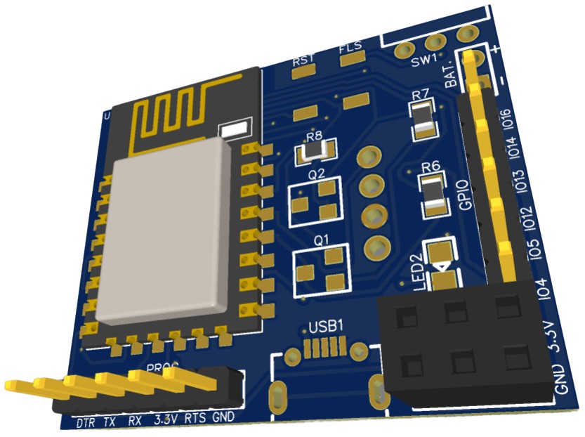
The PCB has SMD components with resistors and capacitors with an SMD package of 0805. The other ICs are also in the SMD package. The front side of the PCB looks something like below.

The backside of the PCB also has some components to assemble. The backside looks something like this.

The Gerber File for the PCB is given below. You can simply download the Gerber File and order the PCB from ALLPCB at 1$ only.
You can use this Gerber file to order high quality PCB for this project. To do that visit the ALLPCB official website by clicking here: https://www.allpcb.com/.

You can now upload the Gerber File by choosing the Quote Now option. From these options, you can choose the Material Type, Dimensions, Quantity, Thickness, Solder Mask Color and other required parameters.

After filling all details, select your country and shipping method. Finally you can place the order.
You can assemble the components on the PCB Board. The 3D view of the PCB looks something like this.
Assembly & Testing the Battery Powered ESP Board
After receiving the PCB from ALLPCB, you can assemble the boards by soldering all the SMD Components on it.
You can start by soldering all the SMD & THT components on the front side first.

Once, soldering is done on the front side, you can solder SMD components & a female header for OLED on the bottom side as well.

Initially there was a design problem for the HT7333 IC as pins were reversed. But in the Gerber files, the problem is fixed, you can directly order the PCB using the Gerber File.
Then you can connect a 3.7V Lithium-Ion Battery to the PCB Board.

To program the board, you need to connect the FTDI module to the PCB Header. Then you can upload the code as there is no need to press any button manually.

In order to charge the battery, plus in a micro-USB cable to the USB Connector. You will see a red LED turns on indicating the Battery Charging.

Uploading a LED Blink Program to Battery Powered ESP Board
Now its time to upload the first program and check the board working. To do that connect a UBS-to-TTL Module like FTDI Module to the board and connect to the computer.

From examples go to the blinking LED Sketch.

From the tools menu, select the Generic ESP8266 Module & also the COM port. Hit the upload button to upload the code.

Once, code uploading is done, the blue LED on the ESP8266 Chip will start blinking indicating the Board is fine.

Meauring the Battery Voltage/Percentage with ADC
As explained in the design part, ESP8266 Chip ADC ranges from 0 to 1V. So a voltage divider network need to be created for stepping down the battery voltage from 4.2V to 1.0V. This is done using a pair of resitors with value R11 (15K) & R12 (47K).
The voltage is measured via ADC Pins and the sample code is given below.
|
1 2 3 4 5 6 7 8 9 10 11 12 13 14 15 16 17 18 19 20 21 22 23 24 25 26 27 28 29 30 31 32 33 34 35 36 37 |
const int analogInPin = A0; void setup() { Serial.begin(115200); } void loop() { float adcValue = analogRead(analogInPin); float voltage = (adcValue / 1023) * 4.2; int bat_percentage = mapfloat (voltage, 3.3, 4.2, 0, 100); if (bat_percentage >= 100) { bat_percentage = 100; } if (bat_percentage <= 0) { bat_percentage = 1; } Serial.print("ADC Value = "); Serial.println(adcValue); Serial.print("Voltage = "); Serial.print(voltage); Serial.println(" V"); Serial.print("Battery Percentage = "); Serial.print(bat_percentage); Serial.println(" %"); delay(1000); } float mapfloat(float x, float in_min, float in_max, float out_min, float out_max) { return (x - in_min) * (out_max - out_min) / (in_max - in_min) + out_min; } |
Copy the above code and paste it on your Arduino IDE. Then upload the code and open the Serial Monitor.
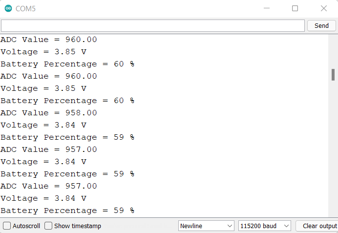
The Serial monitor will print the Battery ADC Value, Battery Voltage, and Percentage as well.
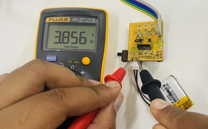
You can use a multimeter and check the battery voltage to compare the value with that of Serial Monitor.
A full version of this project can be found here: DIY IoT Battery Monitoring. Incase if you want to monitor the battery voltage and percentage more precisely, then it is recommended to use MAX17043 fuel gauge IC which removes all the error and limitations.
Creating a ESP8266 Web Server
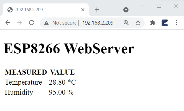
As an IoT project, we can create a Web Server based on ESP8266 Board. For this, we will need a DHT11 Sensor and we will be reading the Humidity and Temperature value. We will display the value on Web Browser using the local IP Address of ESP8266.
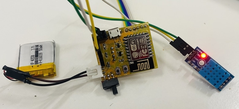
Connect the DHT11 digital pin to ESP8266 GPIO pin 12. Connect the VCC pin of DHT11 to 3.3V & GND to GND.
Add DHT11 Library to the Arduino library folder and then upload the code. But before uploading change the WiFi SSID & Password.
|
1 2 3 4 5 6 7 8 9 10 11 12 13 14 15 16 17 18 19 20 21 22 23 24 25 26 27 28 29 30 31 32 33 34 35 36 37 38 39 40 41 42 43 44 45 46 47 48 49 50 51 52 53 54 55 56 57 58 59 60 61 62 63 64 65 66 67 68 69 70 71 72 73 |
#include <ESP8266WiFi.h> #include <Wire.h> #include "DHT.h" // Uncomment one of the lines below for whatever DHT sensor type you're using! #define DHTTYPE DHT11 // DHT 11, DHT 21 (AM2301), DHT 22 (AM2302 & AM2321) uint8_t DHTPin = 12; DHT dht(DHTPin, DHTTYPE); float Temperature; float Humidity; const char* ssid = "iBall"; const char* password = "abcd1234"; WiFiServer server(80); String header; void setup() { Serial.begin(115200); pinMode(DHTPin, INPUT); dht.begin(); delay(500); Serial.print("Connecting to Wifi Network "); Serial.println(ssid); WiFi.begin(ssid, password); while (WiFi.status() != WL_CONNECTED) { delay(500); Serial.print("."); } Serial.println(""); Serial.println("Successfully connected to WiFi."); Serial.println("IP address: "); Serial.println(WiFi.localIP()); server.begin(); Serial.println("Server started"); } void loop() { Temperature = dht.readTemperature(); Humidity = dht.readHumidity(); WiFiClient client = server.available(); if (client) { Serial.println("Web Client connected "); String request = client.readStringUntil('\r'); client.println("HTTP/1.1 200 OK"); client.println("Content-type:text/html"); client.println("Connection: close"); client.println(); client.println("<!DOCTYPE html><html>"); client.println("<head><meta name=\"viewport\" content=\"width=device-width, initial-scale=1\">"); client.println("<link rel=\"icon\" href=\"data:,\">"); client.println("</style></head><body><h1>ESP8266 WebServer</h1>"); client.println("<table><tr><th>MEASURED</th><th>VALUE</th></tr>"); client.println("<tr><td>Temperature</td><td><span class=\"sensor\">"); client.println(dht.readTemperature()); client.println(" *C</span></td></tr>"); client.println("<tr><td>Humidity</td><td><span class=\"sensor\">"); client.println(dht.readHumidity()); client.println(" %</span></td></tr>"); client.println("</body></html>"); client.stop(); client.println(); Serial.println("Client disconnected."); Serial.println(""); } } |
After uploading code, open Serial Monitor. The Serial Monitor will display the IP Address of ESP8266.
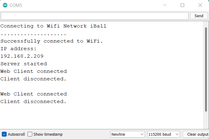
Open your web browser and go to the same IP Address. You will see a beautiful web page with values of temperature and humidity.
This is how you can design your own ESP Board for Low Power or Battery Powered IoT Applications
Video Tutorial & Guide


10 Comments
Hi, you are doing a great job! I want to make this board, but you said you make the board with EasyEDA but you don’t put schematic as a file, you put only a Gerber file. I want to open your schematic direct in EasyEDA, because i want to modidy one part of board. I want to use MAX17043 LipobatteryFuelGauge, instead usin ADC pin. Im suprosed that you don’t implemented this FuelGauge, because you published a project with this module, because battery voltage not drop linear, tou said only way to precise measure percent is with FuelGauge. I need to somehow only modify this in your board and to make it. Can you help me with some tips how to do that correctly, or at least to send me a schematic as a file to import in EasyEDA and to modify to use that chip for measure battery.
Thanks in advance!
Stefan Spurgin
Hello dear thank you for the comment. Please mail us, so that I can share you the EasyEDA source file.
Could the design be modified to have a connector for a solar panel ? I want to increase the autonomy of my sensors.
Can you plz share schematic file on [email protected]
please share the schematic file on [email protected], i want to modify it for my project
please share the schematics on my email [email protected]. I wish to modify it for my project.
Hi, it’s a great website for beginners ! Thanks for sharing !
I would like to change for a esp32 C3, is it possible to send the shematic file to [email protected]
Thanks
Can you please share at: [email protected]
HEllo can you please share the shematic with me, I want to integrate it to my wordclock-project with a neopixel-matrix.
[email protected]
Can you please share at: [email protected]