

Overview
In this project, we will make a DIY ESP32 Based Smart Clock for Weather Forecasting System. A couple of weeks ago I got an electronics kit from Makerfabs which had so many active and passive electronic components. The board also had a PCB Board with SMD components assembled on it. It also included a 1.44” LCD Display along with a 3D Casing. This complete package can be used to design a Smart Clock with Weather Forecasting & Alarming System.

You can also make a real-time clock, which can get the world real-time from the Network timing protocol. You can also set your local time zone easily. It also features an Alarm clock, with a loud noise. And the third best part is it has an online world weather forecaster which gives the data about the local temperature and humidity. You can easily change or alter your address or cities without any re-programming.
Before starting you can follow our ESP32 NTP Clock post to learn more about Network Time Protocol. And in order to purchase this kit, you can visit the Makerfabs Link to directly purchase the kit.
Features: ESP32 Based Smart Clock with Weather Forecasting
- ESP32 WROOM module: WiFi, Bluetooth, 4MB Flash
- 1.44inch 128128 color display, ST7735 driver
- Micro USB interface for programming
- Support Arduino IDE
- 450mAh Lithium-Ion battery
- Support Battery Charging
- Plug-in components, easy soldering
Design & Schematic
The following is the schematic for the project DIY ESP32 Based Smart Clock with Weather Forecasting System.
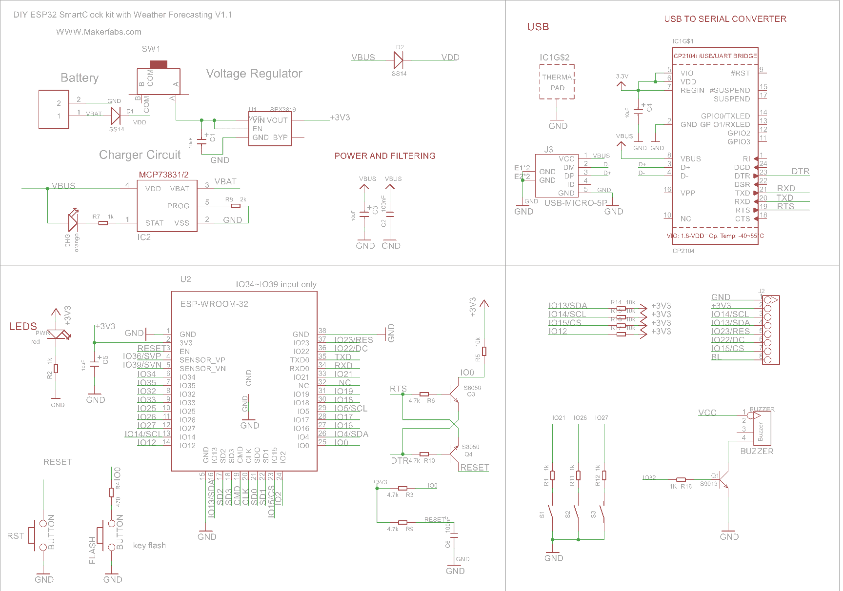
The ESP32-WROOM-32 chip with WiFi and Bluetooth capability is the heart of the project. The LED indication and 3 different push-button switches are directly connected to the ESP32 digital Pin. The 1.44″ SPI Color LCD is interfaced to ESP32 via SPI Pins. The two SMD Push buttons for Reset and Program are connected via transistor for auto programming. This means you don’t need to press any button while uploading the code.
The board has a USB-to-Serial Converter IC CP2104. The CP2104 is a highly-integrated USB-to-UART Bridge Controller providing a USB
2.0 full-speed function controller & USB transceiver function for uploading the firmware. The board also feature some low power voltage regulator along with MCP73831 Battery Charging IC for Battery Management & Charging.
The device is powered via a 3.7V Lithium-Ion battery which makes the device portable. You can also power the device using the USB Cable.
PCB, Part List & Components
The ESP32 Based Smart Clock with Weather Forecasting System Kit contains the following tools inside the box.

- ESP32 SmartClock Kit Mainboard
- Batch of Capacitors& Resistors/Connectors
- Colorful LCD Module
- Lipo Battery
- Acrylic Boards
- Nuts & screws
The front part of the PCB looks something like this.

There are SMD Components that are already soldered on the PCB Board. We need to solder the through-hole components both on the front side and also on the backside. On the backside, we need to solder the three pushbuttons and the LCD Display.

Here is the part list that will help you to solder the components on the board.
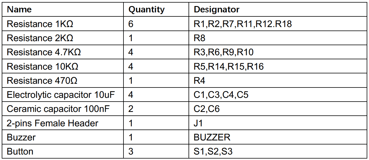
After soldering is done, the front and backside look as follows.


Source Code: ESP32 Smart Clock with Weather Forecasting
The kit comes with pre-programmed firmware. Incase you want to go through the code and make any changes, the you can go to the following Github respository.
The code has the following header file.
|
1 2 3 4 5 6 7 8 |
#include <Adafruit_GFX.h> // Core graphics library #include <Adafruit_ST7735.h> // Hardware-specific library for ST7735 #include <SPI.h> #include "wifi_save.h" #include <WiFi.h> #include "time.h" #include <ArduinoJson.h> #include <HTTPClient.h> |
This is the reason why you need to add following libraries to the Arduino Library Folder.
1. Adafruit_GFX library: https://github.com/adafruit/Adafruit-GFX-Library
2. Adafruit_ST7735 library: https://github.com/adafruit/Adafruit-ST7735-Library
3. ArduinoJson library: https://github.com/bblanchon/ArduinoJson
To upload the code select the “ESP32 Dev Module” and “Huge APP” options and hit the upload button to upload the code.
Testing & Demo
After 1~2 hours soldering and assembly, you can follow the easy steps to set the WiFi SSID and password by phone.

After powering the device, it will try to connect to the previously saved network. If you want to connect to the new network then, follow the instructions displayed on the LCD screen. Press a button for 3 seconds. Then go to your mobile phone and connect to the ESP32 WiFi Network.

Enter the WiFi Credentials and follow as shown in the image below.

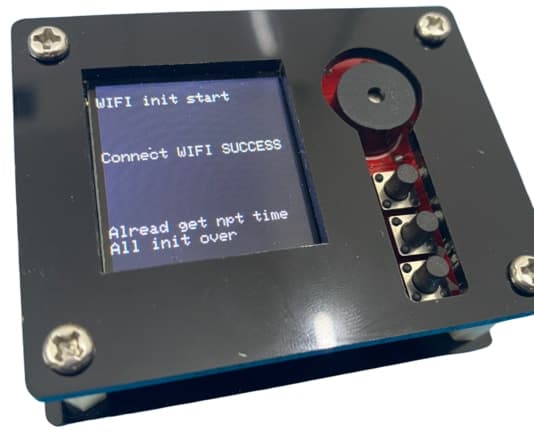
So, once the WiFi gets connected, the device will show connection successful status.
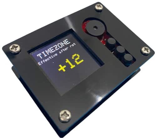
Then it will show the current time and date according to your timezone. It will get the world real-time from the Network timing protocol, you can set your local time zone easily.
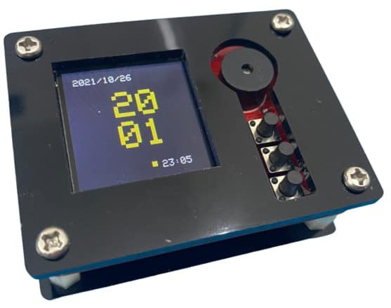
You can change the time zone by using the 3 push buttons.
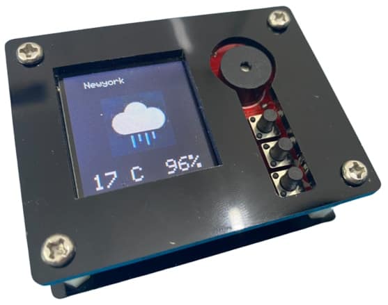
The device can also retrieve the weather data including temperature humidity and atmospheric condition. The device works as an online world weather forecaster, about the local temperature/weather, you can easily change/alter your address/cities without any re-programming

The device can also be used as an Alarm Clock. To change the alarm timing you can use the 3 push buttons and set the time. The buzzer starts automatically during the saved time.

So this is how you can build your own ESP32 Based Smart Clock with Weather Forecasting System.
Video Tutorial & Guide

 & Live Dashboard")


1 Comment
Hallo, beim Kompilieren erhalte ich u.a. folgende Fehlermeldungen:
D:\2_ESP8266 und ESP32\Tutorials\Makerfabs DIY ESP32 Based Smart Clock with Weather Forecasting & Alarm System\SmartClock\SmartClock.ino: In function ‘void tft_init()’:
SmartClock:108:20: error: ‘ST77XX_BLACK’ was not declared in this scope
tft.fillScreen(ST77XX_BLACK);
^
SmartClock:115:22: error: ‘ST77XX_WHITE’ was not declared in this scope
tft.setTextColor(ST77XX_WHITE);
SmartClock:276:37: error: ‘ST77XX_YELLOW’ was not declared in this scope
tft.fillRect(70, 110, 5, 5, ST77XX_YELLOW);
^
martClock:492:26: error: ‘ST77XX_RED’ was not declared in this scope
tft.setTextColor(ST77XX_RED);