

Overview
In this post, we will learn how to design our own Low Power DIY ESP32 board for Battery Powered IoT Applications. The ESP32 microcontrollers from Espressif have become the backbone of modern IoT designs due to their integrated Wi-Fi, Bluetooth connectivity, and robust processing capabilities.
Ready-made development boards such as ESP32 DevKitC or NodeMCU are widely used among hobbyists, makers, and engineers. However, these boards are relatively large in size and include power-hungry voltage regulators, USB-to-UART chips, and other components that may not be suitable for compact and ultra-low-power battery-operated projects. Earlier, we used Battery Powered ESP8266 Board, which was quite good.
To overcome these limitations, it becomes necessary to design a custom ESP32 board optimized for a small form factor and low power consumption. In this article, we will go through the circuit design and PCB considerations for building a compact ESP32 board specifically for battery-powered IoT devices.
Our design incorporates several important features:
- A buck-boost converter (TPS63020) to provide a stable 3.3 V supply from a single-cell Li-ion battery.
- A dedicated Li-ion charging circuit (BQ24092D) with battery management for safe and efficient charging via USB.
- A battery sensing network to monitor the battery voltage directly with the ESP32 ADC.
- Minimal external circuitry for programming: we avoid an on-board USB-to-UART chip (like CP2102 or CH340). Instead, the ESP32 can be programmed using an external FTDI adapter.
By eliminating unnecessary ICs and using efficient power converters, the DIY ESP32 Board reduces both power consumption and board size, making it ideal for IoT nodes powered by small lithium-ion batteries.
Circuit Design & Schematic
Here is the DIY ESP32 Board schematic that can be powered by Battery. We are using the raw ESP32-WROOM Module as the controller. The board consists of a buck-boost converter for a stable 3.3 V output, a battery charging IC for safe USB charging, and a simple battery sense circuit for monitoring.
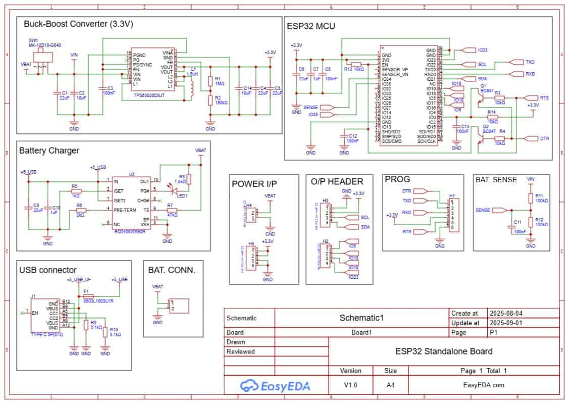
A PROG header is used for programming via external FTDI, and the design avoids on-board USB-to-UART chips to save power and space. The rest of the sections are explained in detail.
- Download: Schematic PDF
- Download: Bill of Materials (BOM)
- Download: Pick & Place File
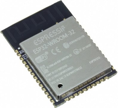
About ESP32-WROOM Module
ESP32-WROOM is a powerful Wi-Fi + Bluetooth module from Espressif designed for IoT applications. The core of the module is the ESP32 SoC, a highly integrated dual-core 32-bit processor with built-in wireless connectivity and rich peripheral support. It can function as a standalone microcontroller or be used to add Wi-Fi and Bluetooth capability to other systems. The module is compact, efficient, and suitable for both low-power designs and high-performance IoT projects.
ESP32-WROOM offers enhanced performance compared to older ESP8266 modules, providing a dual-core CPU, higher clock speed, more GPIOs, and integrated Bluetooth support for BLE and Classic modes. It features low-power modes, fast wake-up, and on-chip power management, making it suitable for battery-operated devices.
- Frequency Range: 2.412 – 2.484 GHz
- CPU: Dual-core Tensilica Xtensa LX6, up to 240 MHz
- RAM: 520 KB SRAM, with external flash support
- Interfaces: SPI, I²C, I²S, UART, CAN, PWM, ADC, DAC, Touch sensor
- Wireless: Wi-Fi 802.11 b/g/n + Bluetooth 4.2 (BR/EDR + BLE)
- Security: WPA/WPA2, encryption with AES, SHA, RSA, ECC
- Operating Voltage: 3.3 V
- Maximum GPIO current: 12 mA typical
- Deep sleep current: < 10 µA
- Wake up and transmit packets in < 2 ms
- Operating Temperature: -40 ºC to +125 ºC
- Onboard PCB antenna and support for external antenna options
Buck-Boost Converter
Most of the ESP32 based boards use linear regulators like AMS1117, which are inefficient for battery powered applications. These regulators have a large dropout voltage and waste considerable power as heat, making them unsuitable when operating from a small Li-ion cell.
As an alternative, this design uses the TPS63020 Buck-Boost Converter IC, which can efficiently regulate the battery voltage to a stable 3.3V output.
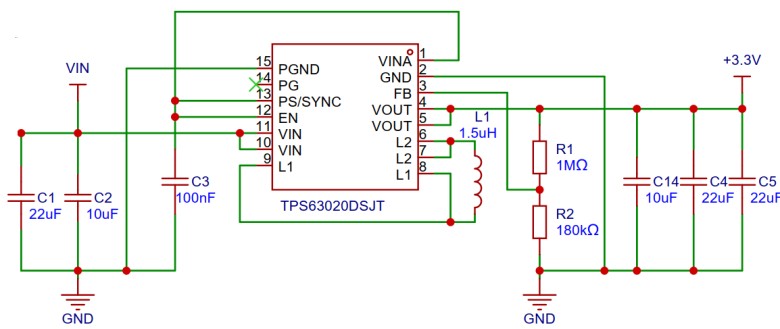
The advantage of a buck-boost regulator is that it can both step-down and step-up the input voltage, ensuring the ESP32 receives a constant 3.3V even when the battery voltage drops below 3.7V. The TPS63020 also has high efficiency and low quiescent current, which makes it ideal for battery powered IoT devices. This IC directly powers the ESP32 module and other circuits, maintaining reliable operation over the entire discharge range of the battery.
Battery Management & Charging
Since the device is powered by a Lithium-Ion battery, there is a need to charge and manage the battery safely. This task is performed by the BQ24092D IC. The BQ24092D is a highly integrated linear charge and power-path management controller designed for space-limited and portable applications. It supports a constant-current/constant-voltage charging algorithm with automatic preconditioning and charge termination.
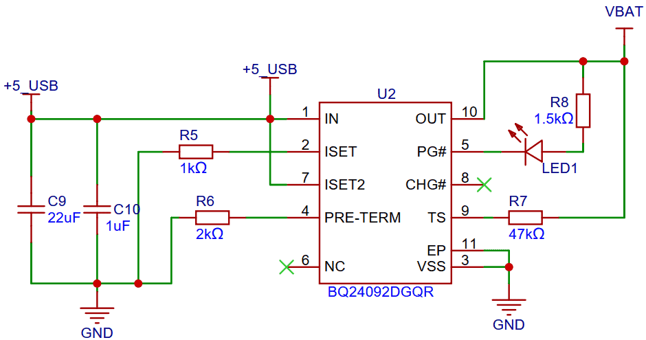
The IC can manage charging from a USB source while powering the system at the same time. It provides built-in safety features such as thermal regulation, current limiting, and over-voltage protection, making it reliable for battery-powered IoT applications. By using this charger IC, the board can efficiently recharge the Li-ion cell through the USB port while ensuring safe and stable operation of the ESP32 and other peripherals.
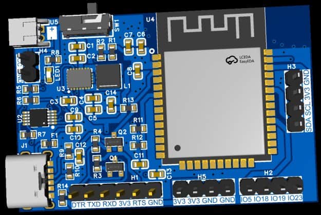
GPIOs & Power Pins
Since this board is designed for multiple IoT applications, you can connect digital sensors and I²C devices directly to the available GPIO pins. The GPIO output pins brought out are IO5, IO18, IO19, and IO23. Among them, IO21 (SDA) and IO22 (SCL) are dedicated for I²C communication.
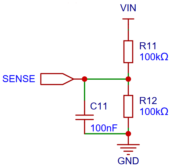
The ESP32 module also includes ADC channels. In this design, the battery voltage is connected to IO34 through a resistor divider (R11 & R12), allowing the ESP32 to measure the battery voltage and calculate the battery percentage.
There is also a header provided in the circuit with multiple pins for power connections. Out of these, 3 pins supply VCC (3.3V) and the other 3 are GND, making it easy to connect external modules and sensors.
OLED Display (Optional)
The OLED Display is optional for this project. But you can use the OLED Display when you want to add a display to your IoT project. The Display that you can use here is the SSD1306 0.96″ I2C OLED Display.
This is how you can design your own Battery Powered ESP32 Powered Board for low power IoT applications.
Programming the ESP32 Chip
The above circuit also supports automatic programming. You just need an external FTDI Module to program the raw ESP32 chip. There is no need to press or release push buttons manually during the upload process. The programming is handled automatically by two transistors (Q1 and Q2), along with a few supporting components connected to the EN and IO0 pins of the ESP32 module.
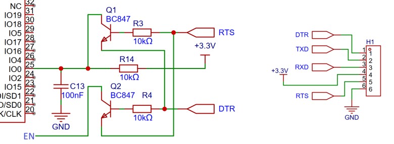
The RTS signal from the FTDI is used to reset the ESP32, while the DTR signal is used to pull the IO0 pin low, putting the chip into flash mode. Transistors Q1 and Q2 ensure proper level shifting and isolation so that the ESP32 is not held in reset when both signals are low. When an upload command is issued from the Arduino IDE or esptool, the ESP32 is automatically put into programming mode and a new sketch can be uploaded. In normal operation, when no upload is triggered, the ESP32 starts in run mode and executes the previously flashed program.
Project PCB Design, Gerber File & PCB Ordering Online
The above schematic is designed using EasyEDA, and it can be directly converted into a PCB layout.
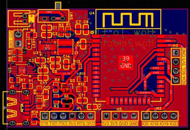
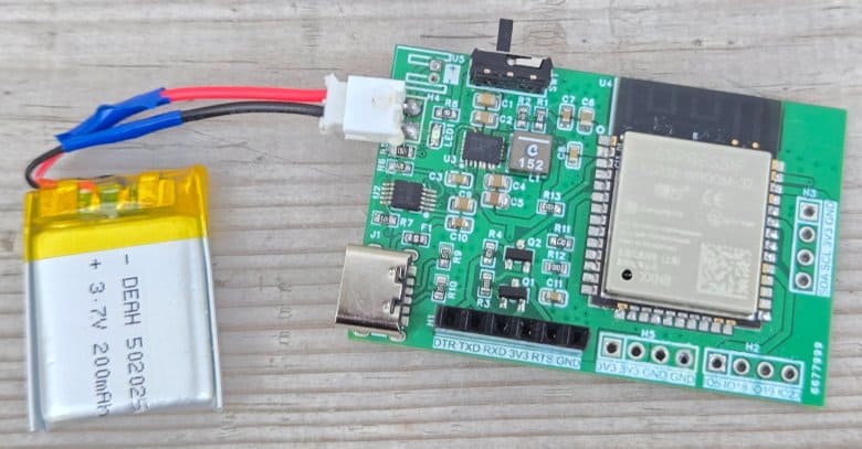
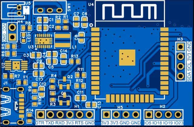
The PCB mainly uses SMD components, with resistors and capacitors in the 0603 package. The ICs, including the buck-boost converter and battery charging IC, are also in SMD packages. The front side of the PCB contains most of the critical components and looks something like this:
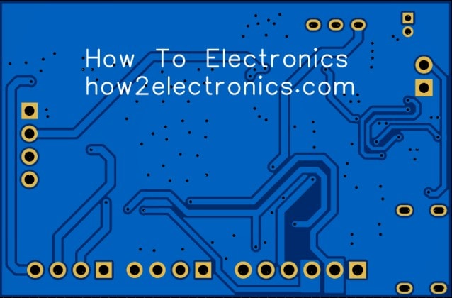
The backside of the PCB also carries a few supporting components that need to be assembled. The rear view of the board is shown below.
The Gerber file for this ESP32-based Battery Powered IoT Board is provided below. You can download the Gerber file and place an order with a PCB manufacturer like ALLPCB for as low as $1.
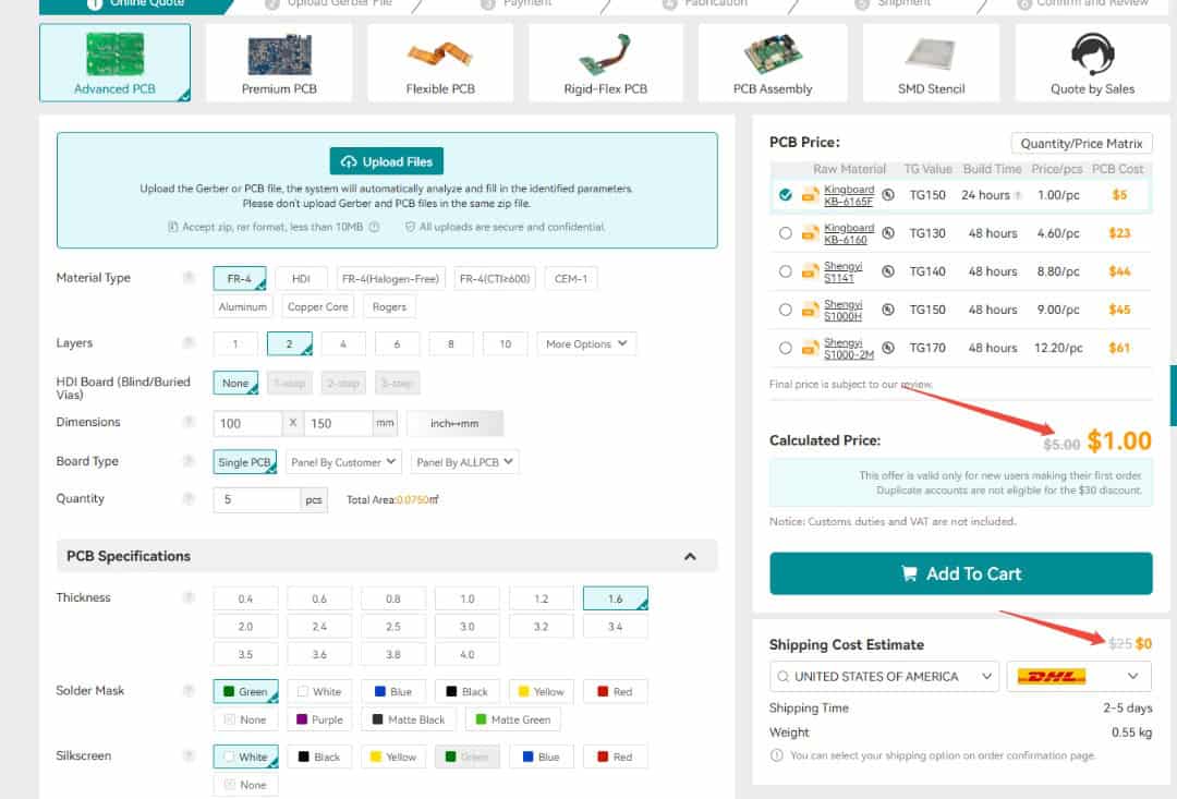
To order the PCB, visit the ALLPCB Official Website and upload the Gerber file using the Quote Now option. You can then choose your required parameters, such as Material Type, Dimensions, Quantity, Thickness, and Solder Mask Color.
ALLPCB is making PCB prototyping more affordable for new users by offering $30 off your first PCB order, plus $30 off shipping. With this promotion, you can enjoy free shipping on your first order—no restrictions on size, layers, or quantity.
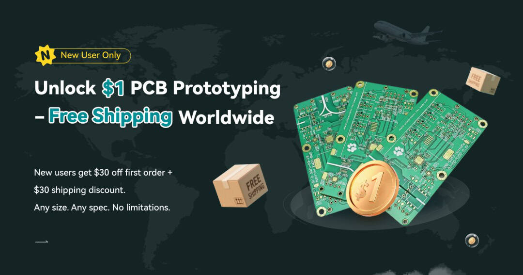
Here is the campaign detail: Unlock $1 PCB Prototyping
Once all the details are filled in, select your country and shipping method. After confirming everything, you can place the order and wait for your boards to arrive.
The 3D view of the PCB design looks like this:
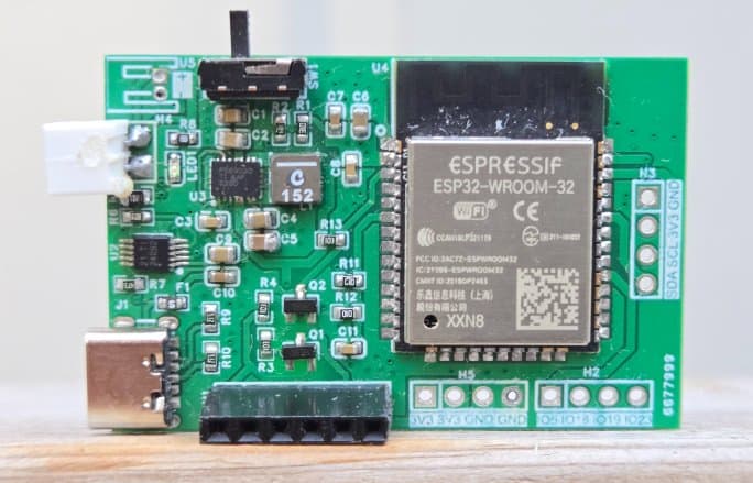
Finally, after receiving the PCB, you can assemble the SMD components and the ESP32 module on the board.
Assembly & Testing the DIY Battery Powered ESP32 Board
After one week, I received the PCB box from ALLPCB.
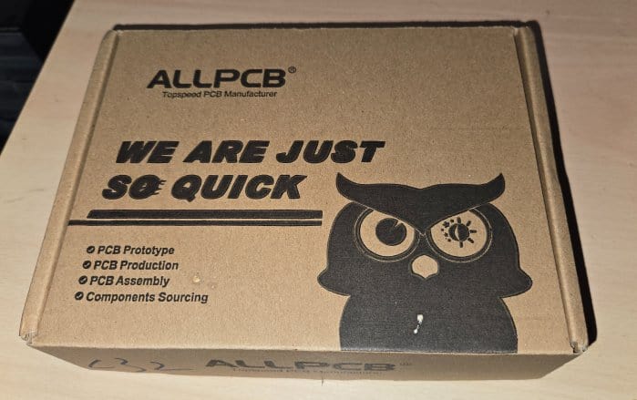
The box contained the PCB as expected. The quality was super fine and I could finally use it make my DIY Battery Powered ESP32 Board.
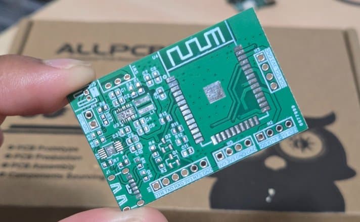
After receiving the PCB from ALLPCB, you can begin by soldering all the SMD components on the front side of the board.
The layout has been kept compact, and only the front side contains the ESP32 module, buck-boost converter, battery charging IC, resistors, and capacitors.
During the first revision, there were only a few minor issues with capacitor and resistor values, but these have been corrected in the final Gerber files. You can safely order and assemble the board directly using the updated files without any footprint concerns.
Once assembled, connect a 3.7V Lithium-Ion battery to the battery connector.
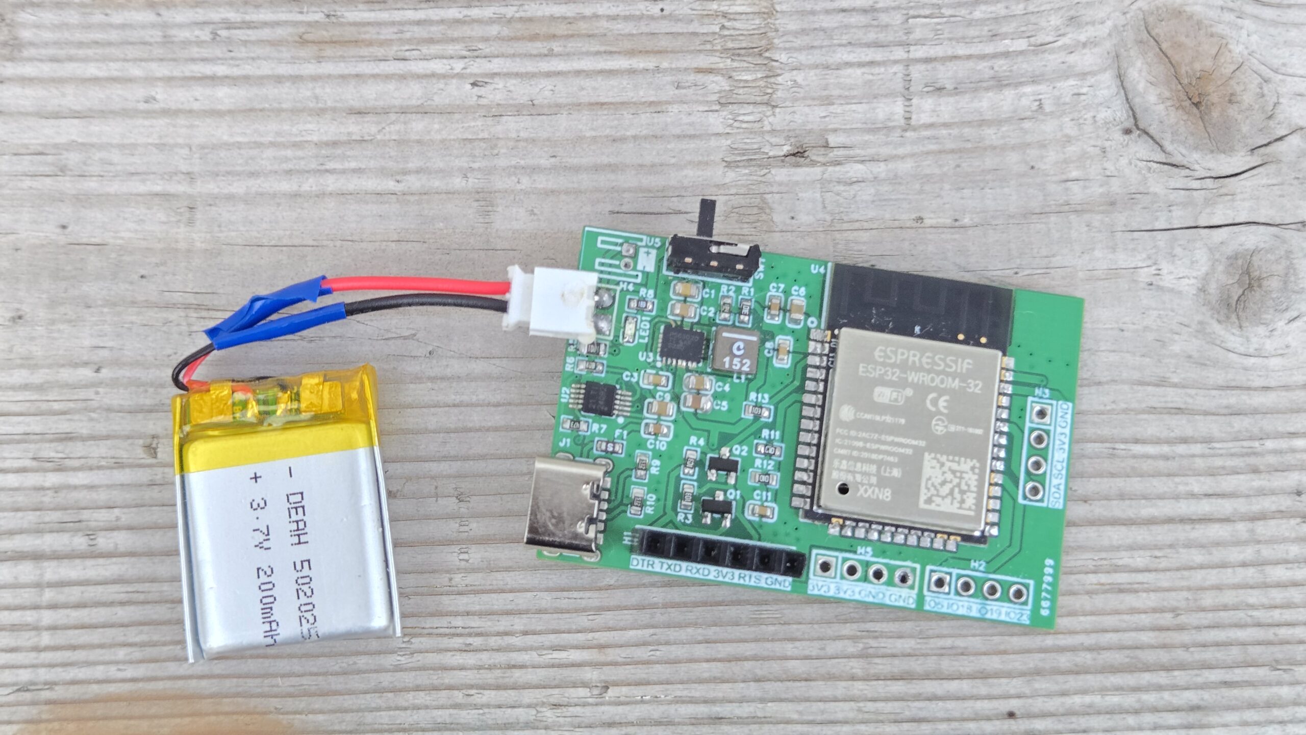
To program the ESP32 module, connect an FTDI programmer to the PROG header. The programming process is automatic—there’s no need to press reset or boot buttons manually.
For charging, simply plug in a Type-C USB cable to the onboard USB connector. A red LED will light up to indicate USB power.
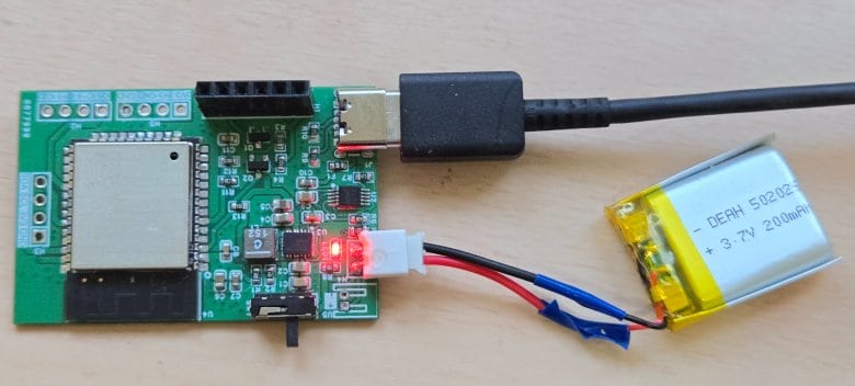
You can use a multimeter and check if the battery is being charged or not, as there will be an increase in battery voltage during charging.
Uploading a Test Code to Battery Powered ESP32 Board
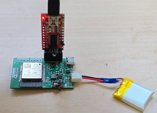
Once the hardware assembly is complete and the battery is connected, you can upload an example code to verify that the board is working properly. Simply connect your FTDI module directly to the PROG header on the PCB.
Open the Arduino IDE, copy the example code, and paste it into a new sketch. From the Tools → Board Manager, select ESP32 Dev Module as the board type, and also choose the correct COM port corresponding to your FTDI adapter.
|
1 2 3 4 5 6 7 8 9 10 11 12 13 14 15 16 17 18 19 20 21 22 23 24 25 26 27 28 29 30 31 32 33 34 35 36 37 38 39 40 41 42 43 44 45 46 47 48 49 50 51 52 53 54 |
#define SENSE_PIN 34 #define NUM_SAMPLES 32 // Divider values (Ohms) const float R_TOP = 100000.0f; // R11 const float R_BOTTOM = 100000.0f; // R12 const float DIVIDER_GAIN = (R_TOP + R_BOTTOM) / R_BOTTOM; // = 2.0 with 100k/100k void setup() { Serial.begin(115200); delay(300); // On ESP32 you can set width/atten globally analogReadResolution(12); // 12-bit (0..4095) analogSetAttenuation(ADC_11db); // allows ~0–3.9V on ADC input Serial.println(F("ESP32 Battery Voltage Reader (IO34, 100k/100k divider)")); } uint16_t readRawAverage(uint8_t pin, uint16_t n) { uint32_t acc = 0; for (uint16_t i = 0; i < n; i++) { acc += analogRead(pin); delayMicroseconds(200); } return (uint16_t)(acc / n); } uint32_t readMilliVoltsAverage(uint8_t pin, uint16_t n) { uint32_t acc = 0; for (uint16_t i = 0; i < n; i++) { acc += analogReadMilliVolts(pin); // calibrated mV delayMicroseconds(200); } return acc / n; // mV at the pin } void loop() { uint16_t raw = readRawAverage(SENSE_PIN, NUM_SAMPLES); uint32_t vSense_mV = readMilliVoltsAverage(SENSE_PIN, NUM_SAMPLES); // Undo the divider to compute battery voltage float vBat_V = (vSense_mV * DIVIDER_GAIN) / 1000.0f; // volts Serial.print(F("RAW=")); Serial.print(raw); Serial.print(F(" Vsense=")); Serial.print(vSense_mV / 1000.0f, 3); Serial.print(F(" V Vbat=")); Serial.print(vBat_V, 3); Serial.println(F(" V")); delay(500); } |
Finally, click the Upload button. The code will be automatically uploaded to your ESP32 board without the need to press any reset or boot buttons.
After successfully uploading the sketch, open the Serial Monitor in the Arduino IDE. Make sure the baud rate is set to 115200.
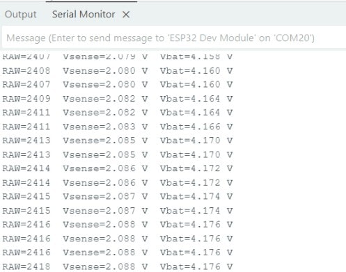
If everything is working correctly, the Serial Monitor will begin displaying continuous readings of the raw ADC values, the sensed voltage at the ESP32 pin, and the calculated battery voltage. You may build an IoT Battery SoC Monitoring System project using this board.
This is how you can design and assemble your own battery-powered ESP32 board for compact and energy-efficient IoT applications.
Video Tutorial & Guide

 & Live Dashboard")


