
 Monitoring System with ESP32")
Overview
In this post, we will learn how to build an IoT Based Battery SoC (%) Monitoring System using ESP32. The ESP32 module from Espressif is a powerful microcontroller with integrated Wi-Fi and Bluetooth, making it ideal for connected and battery-powered applications.
This project is based on a DIY ESP32 Battery Powered IoT Board with a built-in Battery Management and Charging System. The board can charge any single-cell Lithium-Ion or Lithium-Polymer battery using a BQ24092D charging IC, while a TPS63020 buck-boost converter provides a stable 3.3 V supply to the ESP32. A simple battery sensing circuit connected to the ESP32 ADC pin allows accurate measurement of the battery voltage, from which the State of Charge (SoC %) can be calculated.
Since the battery is the primary power source, constant monitoring is essential to prevent overcharging, deep discharging, or failure. The charging IC ensures safe charging with auto cut-off, while the ESP32 continuously measures the battery status. Unlike older systems where battery management was limited to LED indicators, the integration of IoT allows users to monitor the battery remotely from a ThingSpeak dashboard on a computer or smartphone.
Our design incorporates several important features:
- A buck-boost converter (TPS63020) for stable 3.3 V operation.
- A Li-ion charging IC (BQ24092D) for safe USB charging and battery management.
- A battery sensing network for measuring voltage and calculating SoC.
- IoT integration via ESP32 Wi-Fi for sending real-time battery data to ThingSpeak.
- An optional OLED display for local monitoring without Wi-Fi.
Circuit Design & Schematic
Let’s walk through the hardware design of IoT based Battery SoC (%) Monitoring System with ESP32 in detail.
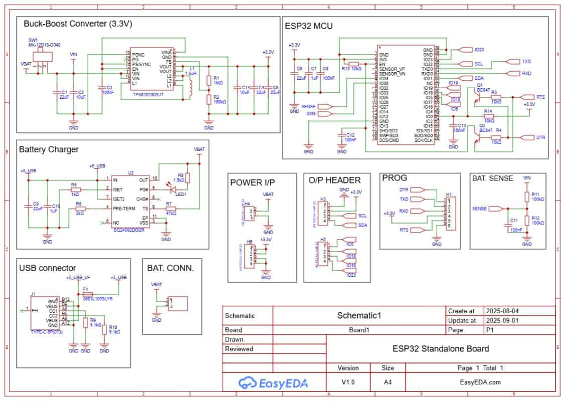
The board is powered and charged through a USB Type-C port. Charging is handled by the BQ24092D IC. It supports CC/CV charging, pre-conditioning, and auto cut-off. A small LED indicates charging status. A JST-PH connector is used to connect a 3.7 V Li-ion/LiPo battery. A slide switch is added to turn the system on or off.
The regulated supply is provided by the TPS63020 buck-boost converter. It ensures a stable 3.3 V output across the entire battery range (3.0–4.2 V). This keeps the ESP32 powered even at low battery levels.
Battery voltage is measured using a simple resistor divider (R11 = 100 kΩ, R12 = 100 kΩ). A small capacitor (C11 ≈ 100 nF) is added as a filter. The divided voltage is fed to ADC pin IO34 of the ESP32. In software, this value is converted back to the real battery voltage and percentage.
Programming is done through the PROG header using an FTDI adapter. Two transistors, Q1 and Q2, handle the auto-reset and auto-boot. This means no buttons are needed during code upload.
Extra GPIO pins are broken out for sensors and modules. IO4 (SDA) and IO5 (SCL) provide an I²C interface for connecting an OLED display. This allows battery voltage and percentage to be viewed locally without Wi-Fi.
- Download: Schematic PDF
- Download: Bill of Materials (BOM)
- Download: Pick & Place File
BQ24092D Battery Management & Charging IC
Since the device is powered by a Lithium-Ion cell, safe charging and management are critical. This is handled by the BQ24092D IC, a highly integrated linear charger and power-path management controller from Texas Instruments.
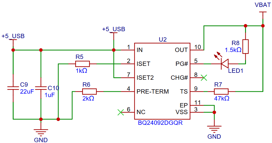
The BQ24092D is designed for portable applications and supports a constant-current / constant-voltage (CC/CV) charging algorithm. It automatically manages preconditioning, fast charging, and charge termination. The IC can seamlessly provide power to the system while charging the battery, thanks to its dynamic power-path management feature.
Key Technical Features
- Input Voltage Range: 4.35 V to 6.4 V (USB or adapter input)
- Charge Current: Programmable up to 1 A (set by external resistor)
- Power-Path Management: Allows simultaneous battery charging and system powering
- Preconditioning: Automatic low-current charging for deeply discharged cells (< 3.0 V)
- Fast-Charge: Supplies constant current until battery approaches 4.2 V
- Termination: Automatic charge termination when the current falls below a preset threshold
- Recharge: Automatically restarts charging if battery voltage drops below ~4.05 V
- Status Indication: Open-drain outputs for charge status (charging, done, fault)
- Safety Protections:
-
- Thermal regulation (reduces charge current if IC overheats)
- Input current limiting (protects USB ports from overdraw)
- Over-voltage protection (protects battery and circuit)
- Short-circuit and reverse current protection
Why BQ24092D in This Board?
By using the BQ24092D, the ESP32 IoT board achieves reliable, safe, and efficient charging. It ensures the battery is never overcharged or overheated, while still delivering stable 3.3 V to the ESP32 and peripherals through the buck-boost converter (TPS63020). The status LED makes it easy to check charging conditions at a glance.
This IC is especially useful for IoT devices that run continuously. Even when the battery is empty, the system can run from USB power without interruptions.
Battery Voltage Sensing with ESP32 ADC
To monitor the battery level, the ESP32 uses one of its ADC pins (IO34). Since the battery voltage of a single-cell Li-ion/LiPo ranges from 3.0 V (discharged) up to 4.2 V (fully charged), it cannot be fed directly into the ADC without scaling. The ESP32 ADC input range (with 11 dB attenuation) supports about 0–3.9 V, so a voltage divider network is required.
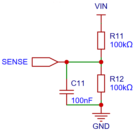
In this design, two 100 kΩ resistors (R11 and R12) are used as a divider. This reduces the battery voltage by half before feeding it to the ADC pin:
Vsense = (R12 / (R11 + R12)) × Vbat
With R11 = R12 = 100 kΩ, the divider ratio is 1:2, meaning:
Vsense = 0.5 × Vbat
So when the battery is at 4.2 V, the ADC pin only sees about 2.1 V, which is safe.
Noise Filtering
To improve measurement stability, a small capacitor (C11 ≈ 100 nF) is added across R12. This forms an RC filter that smooths out switching noise from the buck-boost converter and charger IC.
ADC Reading & Conversion
- The ESP32 reads the divided voltage as
Vsense. - In software, the actual battery voltage is calculated as:
Vbat = Vsense × 2 - From this voltage, the State of Charge (SoC %) is estimated using a lookup table or interpolation based on Li-ion discharge curves.
Design Considerations
- High-value resistors (100 kΩ each) are used to minimize current drain from the battery (<20 µA).
- A calibration offset is applied in software since ESP32 ADCs are not perfectly linear.
- IO34 is an input-only ADC pin, so it’s ideal for sensing applications.
Project PCB Design, Gerber File & PCB Ordering Online
The schematic of the IoT Battery SoC Monitoring System with ESP32 was created in EasyEDA, and from there it was converted into a compact PCB layout.
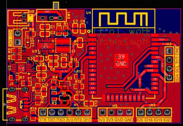
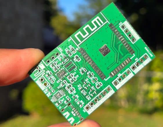
The board is designed with mostly SMD components to keep the size small. Resistors and capacitors are in the 0603 package, while the main ICs, such as the TPS63020 buck-boost converter and the BQ24092D battery charger, are also in SMD form.
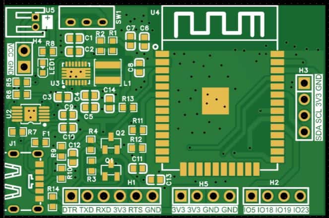
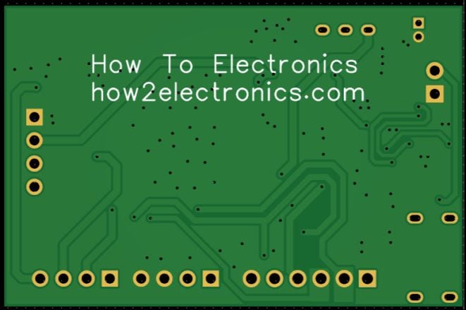
All of the critical components, including the ESP32-WROOM module, are placed on the front side of the PCB, which makes assembly easier and more reliable.
The Gerber files for this board are available and can be used to place an order directly with ALLPCB. They offer PCB prototyping services at very low cost, and new users get extra benefits.
Ordering is straightforward: go to the ALLPCB Official Website. Then upload the Gerber files using the Quote Now option, and choose your board parameters like material, dimensions, thickness, quantity, and solder mask color.
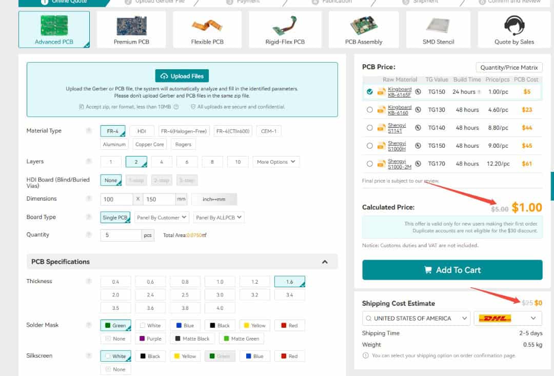
Currently, ALLPCB provides a special promotion for new users — $30 off the first PCB order and $30 off shipping, effectively giving you free shipping with no restrictions on board size, layers, or quantity.

Here is the campaign detail: Unlock $1 PCB Prototyping
Once you finalize the details, select your shipping option, confirm the order, and wait for the boards to be delivered.
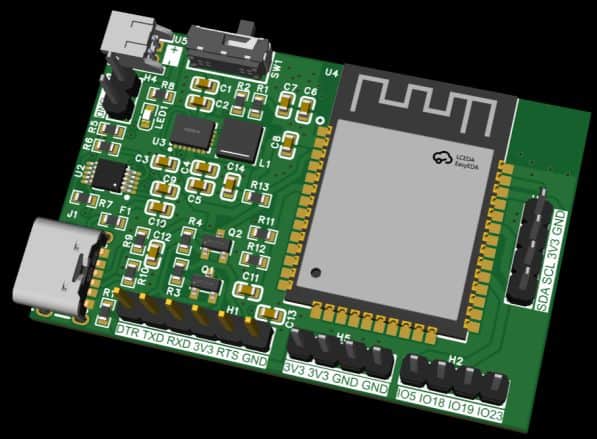
The 3D preview of the PCB design shows the placement of the ESP32, power management ICs, and passive components neatly arranged on the front side.
Assembly & Testing the DIY Battery Powered ESP32 Board
After about a week, the finished PCBs arrived from ALLPCB. The quality was excellent, with smooth solder pads and precise silkscreen printing—perfect for assembling the ESP32 IoT board.
Assembly begins with soldering all the SMD components on the front side. The design is compact, so only the front contains the ESP32 module, buck-boost converter, charger IC, and supporting resistors and capacitors.
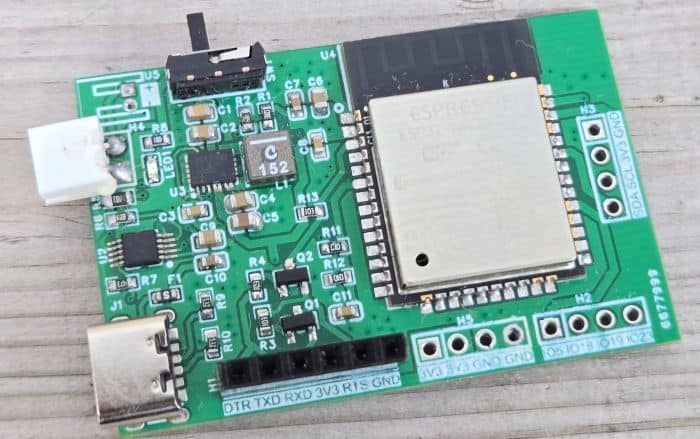
In the first prototype there were a few minor value adjustments for capacitors and resistors, but these have been corrected in the final Gerber release, so you can assemble the latest version without any issues.
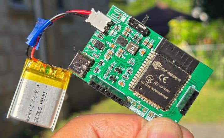
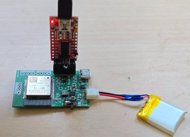
Once assembled, connect a 3.7 V Li-ion/LiPo battery to the JST connector. Programming the ESP32 is done through the PROG header with an FTDI adapter. Thanks to the automatic reset circuitry, there’s no need to press boot or reset buttons—the upload process is completely automatic.
For charging, simply plug in a USB Type-C cable. A red LED will indicate charging, and you can verify it by checking the battery voltage with a multimeter.
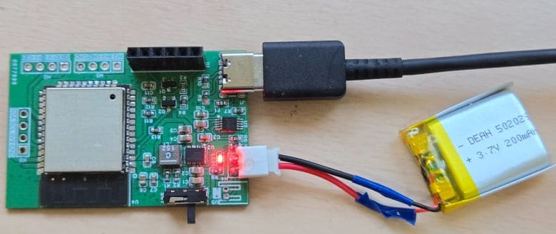
The voltage should gradually increase during charging, confirming that the system is working properly.
Setting up ThingSpeak Server
Now let’s move to the IoT part of this project. Using the ESP32 ADC on IO34, we read the battery voltage, calculate the percentage, and send this data to ThingSpeak over Wi-Fi. First you need to setup the Thingspeak Server.

Go to ThingSpeak and sign up (or log in if you already have an account).
- From the dashboard, click New Channel.
- Give it a name (e.g., Battery Monitoring).
- Add Fields for your data (e.g., Battery Voltage, Battery SoC (%)).
- Save the channel.
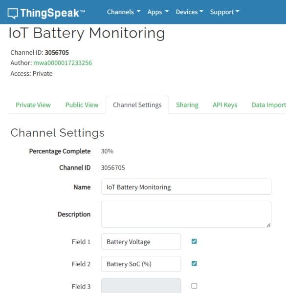
- Open your channel settings.
- Under the API Keys tab, copy the Write API Key.
- You’ll use this key in your ESP32 code to send data.
Code: IoT based Battery SoC (%) Monitoring System with ESP32
Here is the final code for the project. This ESP32 code implements a IoT based Battery SoC (%) Monitoring System with deep sleep for ultra-low power consumption. On each wake cycle, the ESP32 measures the battery voltage using IO34 connected to a resistor divider (100k/100k). The raw ADC readings are corrected with calibration and an offset to match multimeter accuracy. The script then converts the voltage into State of Charge (SoC %) using an OCV (open-circuit voltage) lookup table.
Once the voltage and SoC are calculated, the ESP32 tries to connect to Wi-Fi (with up to 5 retries). If successful, it uploads the readings to ThingSpeak using a simple HTTP GET request. If Wi-Fi fails, the device skips uploading and continues. After uploading, it shuts down Wi-Fi and Bluetooth, then enters deep sleep mode for 30 seconds.
From the following lines, change the WiFi SSID, Password and API Key for Thingspeak Server.
|
1 2 3 4 5 |
// Wi-Fi const char* WIFI_SSID = "*******************"; const char* WIFI_PASS = "*******************"; // ThingSpeak const char* TS_API_KEY = "*******************"; // Channel write key |
Once these changes are done, you can upload the code to the ESP32 Board.
|
1 2 3 4 5 6 7 8 9 10 11 12 13 14 15 16 17 18 19 20 21 22 23 24 25 26 27 28 29 30 31 32 33 34 35 36 37 38 39 40 41 42 43 44 45 46 47 48 49 50 51 52 53 54 55 56 57 58 59 60 61 62 63 64 65 66 67 68 69 70 71 72 73 74 75 76 77 78 79 80 81 82 83 84 85 86 87 88 89 90 91 92 93 94 95 96 97 98 99 100 101 102 103 104 105 106 107 108 109 110 111 112 113 114 115 116 117 118 119 120 121 122 123 124 125 126 127 128 129 130 131 132 133 134 135 136 137 138 139 140 141 142 143 144 145 146 147 148 149 150 151 152 153 154 155 156 157 158 159 160 161 162 163 164 165 166 167 168 169 170 171 172 173 174 175 176 177 178 179 180 181 182 183 184 185 186 187 188 189 190 191 192 193 194 195 196 197 198 199 200 201 202 203 204 205 206 207 208 209 210 211 212 213 214 215 216 217 218 219 220 221 222 223 224 225 226 227 228 229 230 231 232 |
/* ESP32 Battery → ThingSpeak with Deep Sleep ------------------------------------------ Cycle: 1) Wake from deep sleep every 30 s (timer). 2) Read battery voltage (IO34, 100k/100k divider) + SoC% (OCV lookup). 3) Try to connect Wi-Fi (up to 5 retries). 4) If connected, upload to ThingSpeak (field1=Vbat, field2=SoC). 5) Disconnect Wi-Fi and go back to deep sleep. Notes: - Uses analogReadMilliVolts() (eFuse-calibrated) + optional piecewise ADC calibration + OFFSET_V. - SoC clamped to [1..100] for display & upload. - ThingSpeak rate limit is 15 s; our cycle is 30 s → safe. */ #include <Arduino.h> #include <WiFi.h> // ====================== USER CONFIG ====================== // Wi-Fi const char* WIFI_SSID = "Ab-Fiber-Internet"; const char* WIFI_PASS = "CommonSense2025"; // ThingSpeak const char* TS_HOST = "api.thingspeak.com"; const char* TS_API_KEY = "EJI3C234QKDV47Y7"; // Channel write key // Sleep / retries const uint32_t SLEEP_SECONDS = 30; // deep sleep interval const uint8_t WIFI_MAX_RETRIES = 5; // number of Wi-Fi attempts per wake const uint32_t WIFI_RETRY_DELAY_MS = 1000; // delay between retries // ADC / sense pin #define SENSE_PIN 34 // IO34 (ADC1_CH6) #define NUM_SAMPLES 32 // oversampling for stability // Divider resistors (R_TOP from VBAT to sense, R_BOTTOM from sense to GND) const float R_TOP = 100000.0f; // ohms const float R_BOTTOM = 100000.0f; // ohms const float DIVIDER_GAIN = (R_TOP + R_BOTTOM) / R_BOTTOM; // = 2.0 for 100k/100k // Global offset (Volts) to align with multimeter. // Example: Serial 3.8V vs DMM 3.7V → OFFSET_V = -0.10f const float OFFSET_V = -0.10f; // ADC calibration table (mV at the pin). // CAL_X_MV: reported by analogReadMilliVolts(), CAL_Y_MV: true (DMM) value. // Identity mapping by default; add your measured pairs if you want extra accuracy. const float CAL_X_MV[] = { 0, 600, 1200, 1800, 2200 }; const float CAL_Y_MV[] = { 0, 600, 1200, 1800, 2200 }; const size_t CAL_N = sizeof(CAL_X_MV) / sizeof(CAL_X_MV[0]); // Li-ion OCV → SoC table (typical single cell @ ~25 °C) struct VP { float V; float P; }; const VP OCV[] = { {4.20, 100}, {4.12, 95}, {4.08, 90}, {4.04, 85}, {4.00, 80}, {3.97, 75}, {3.92, 70}, {3.89, 65}, {3.85, 60}, {3.82, 55}, {3.79, 50}, {3.77, 45}, {3.75, 40}, {3.73, 35}, {3.71, 30}, {3.69, 25}, {3.66, 20}, {3.62, 15}, {3.58, 10}, {3.50, 5}, {3.30, 0} }; const size_t OCV_N = sizeof(OCV) / sizeof(OCV[0]); // ====================== HELPERS ====================== // Average multiple ADC reads in mV (uses ESP32 eFuse calibration) static uint32_t readMilliVoltsAverage(uint8_t pin, uint16_t n) { uint32_t acc = 0; for (uint16_t i = 0; i < n; i++) { acc += analogReadMilliVolts(pin); delayMicroseconds(200); } return acc / n; } // Piecewise-linear interpolation (for ADC calibration / OCV curve) static float pwlInterp(float x, const float *xv, const float *yv, size_t n) { if (n < 2) return x; if (x <= xv[0]) return yv[0]; if (x >= xv[n - 1]) return yv[n - 1]; for (size_t i = 0; i < n - 1; i++) { if (x >= xv[i] && x <= xv[i + 1]) { float t = (x - xv[i]) / (xv[i + 1] - xv[i]); return yv[i] + t * (yv[i + 1] - yv[i]); } } return x; // fallback } // Convert battery voltage to SoC (%), unclamped static float socFromVoltage(float vbat) { if (vbat >= OCV[0].V) return 100.0f; if (vbat <= OCV[OCV_N - 1].V) return 0.0f; for (size_t i = 0; i < OCV_N - 1; i++) { if (vbat <= OCV[i].V && vbat >= OCV[i + 1].V) { float t = (vbat - OCV[i + 1].V) / (OCV[i].V - OCV[i + 1].V); return OCV[i + 1].P + t * (OCV[i].P - OCV[i + 1].P); } } return 0.0f; } // Read battery voltage (V) and SoC (%) with calibration & clamping static void readBattery(float &vBat, float &soc) { // 1) Pin voltage in mV (average) const uint32_t vSense_raw_mV = readMilliVoltsAverage(SENSE_PIN, NUM_SAMPLES); // 2) Correct residual non-linearity via piecewise calibration const float vSense_corr_mV = pwlInterp((float)vSense_raw_mV, CAL_X_MV, CAL_Y_MV, CAL_N); // 3) Undo divider → battery voltage in Volts vBat = (vSense_corr_mV * DIVIDER_GAIN) / 1000.0f; // 4) Apply global offset (align to DMM) vBat += OFFSET_V; // 5) Compute SoC and clamp to [1..100] for display/upload soc = socFromVoltage(vBat); if (soc < 1.0f) soc = 1.0f; if (soc > 100.0f) soc = 100.0f; } // Try to connect Wi-Fi with limited retries static bool connectWiFiWithRetries() { WiFi.mode(WIFI_STA); WiFi.begin(WIFI_SSID, WIFI_PASS); for (uint8_t attempt = 1; attempt <= WIFI_MAX_RETRIES; attempt++) { uint32_t t0 = millis(); while (WiFi.status() != WL_CONNECTED && (millis() - t0) < WIFI_RETRY_DELAY_MS) { delay(50); } if (WiFi.status() == WL_CONNECTED) { return true; } // retry } return false; } // Upload to ThingSpeak (HTTP GET). Returns true on HTTP 200. static bool postToThingSpeak(float vBat, float soc) { if (WiFi.status() != WL_CONNECTED) return false; char url[160]; snprintf(url, sizeof(url), "/update?api_key=%s&field1=%.3f&field2=%.1f", TS_API_KEY, vBat, soc); WiFiClient client; if (!client.connect(TS_HOST, 80)) { return false; } client.print(String("GET ") + url + " HTTP/1.1\r\n"); client.print(String("Host: ") + TS_HOST + "\r\n"); client.print("Connection: close\r\n\r\n"); // Minimal read of status line int statusCode = -1; uint32_t tStart = millis(); while (client.connected() && (millis() - tStart) < 5000) { if (client.available()) { String line = client.readStringUntil('\n'); // "HTTP/1.1 200 OK" if (line.startsWith("HTTP/1.1 ")) { statusCode = line.substring(9, 12).toInt(); break; } } delay(10); } while (client.connected() && client.available()) { client.read(); } client.stop(); return (statusCode == 200); } // Clean shutdown of Wi-Fi before deep sleep static void shutdownWiFi() { if (WiFi.status() == WL_CONNECTED) { WiFi.disconnect(true, true); // drop AP and erase config in RAM } WiFi.mode(WIFI_OFF); btStop(); // ensure BT stack is off too (saves µA) } // Enter deep sleep for SLEEP_SECONDS static void goToDeepSleep() { // Configure timer wakeup esp_sleep_enable_timer_wakeup((uint64_t)SLEEP_SECONDS * 1000000ULL); Serial.flush(); esp_deep_sleep_start(); } // ====================== MAIN ====================== void setup() { Serial.begin(115200); delay(100); // Configure ADC for this session analogReadResolution(12); // 0..4095 analogSetAttenuation(ADC_11db); // up to ~3.9 V at the pin // Small banner (helpful during bring-up; negligible energy impact) Serial.println("\n[Wake] ESP32 Battery → ThingSpeak deep-sleep node"); // 1) Measure battery now (before Wi-Fi to keep awake time short) float vBat = 0, soc = 0; readBattery(vBat, soc); Serial.printf("Vbat=%.3f V SoC=%.1f %%\n", vBat, soc); // 2) Try Wi-Fi up to WIFI_MAX_RETRIES bool wifiOK = connectWiFiWithRetries(); Serial.println(wifiOK ? "WiFi: connected" : "WiFi: failed after retries"); // 3) If connected, upload once if (wifiOK) { bool ok = postToThingSpeak(vBat, soc); Serial.println(ok ? "ThingSpeak: OK" : "ThingSpeak: FAIL"); } // 4) Power down radios and sleep shutdownWiFi(); Serial.printf("Sleeping for %lus...\n", (unsigned long)SLEEP_SECONDS); goToDeepSleep(); } void loop() { // Not used. We always deep sleep from setup(). } |
Testing and Results
After preparing the hardware and assembling all components, the next step was testing the system. I uploaded the ESP32 battery monitoring and IoT code to the chip using the FTDI programmer connected to the PROG header. Once the upload was complete, I opened the Serial Monitor in Arduino IDE.
The Serial Monitor immediately displayed the ADC values, the calculated battery voltage, and the SoC (%). This confirmed that the voltage divider, calibration, and SoC conversion were working correctly.
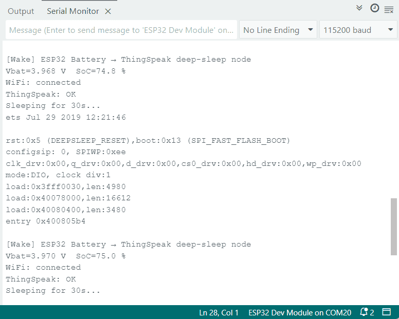
Every 30 seconds, the ESP32 connected to Wi-Fi and pushed the measured battery data to the ThingSpeak server. On the ThingSpeak dashboard, I could see real-time plots of both the battery voltage (V) and state of charge (%). Alongside the graphs, the numeric real-time values for voltage and SoC were also displayed, giving a clear and accurate picture of the battery status.
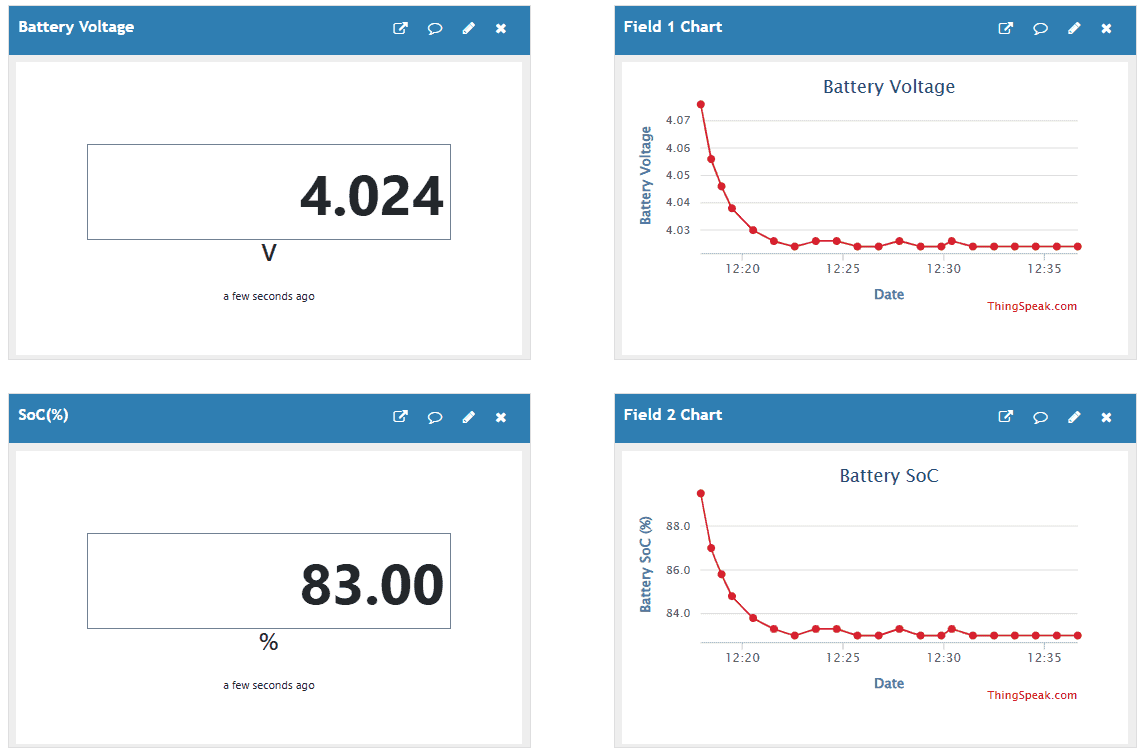
When the battery was connected to a charger, the ThingSpeak graph showed a steady rise in voltage, eventually reaching the maximum of 4.2 V as the battery charged. During discharge, the graph gradually declined, but very slowly—thanks to the ESP32’s low power deep-sleep design, which reduced power draw to just a few microamps.
With this, the DIY ESP32 Battery Powered IoT Board, you can successfully monitor the online battery voltage and SoC monitoring in real-time.
 & Live Dashboard")


