

Overview
In this tutorial, we will be interfacing PN532 NFC RFID Module with Arduino Board in all the three UART, I2C & SPI Modes. PN532 is an NFC RFID module, popular in enabling your mobile payment and serves as a tool for other communications in your smartphone. It can be found embedded in modules, that allow for easy pairing with your Arduino projects.
The RC522 module is certainly the best-known RFID module for the Arduino projects. But the PN532 NFC RFID reader has certain advantages over RC522, particularly in terms of communication options. We will see here how to use PN532 NFC RFID Module with Arduino according to the different communication methods UART, SPI & I2C. Later we will display the UID numbers of the NFC card on a 0.96″ OLED Display.
Bill of Materials
We require following components for this tutorial. You can purchase all these components from the following Amazon link.
| S.N. | Components Name | Quantity | Purchase Links |
|---|---|---|---|
| 1 | Arduino Nano Board | 1 | Amazon | AliExpress |
| 2 | PN532 NFC RFID Module | 1 | Amazon | AliExpress |
| 3 | 0.96" I2C OLED Display | 1 | Amazon | AliExpress |
| 4 | Connecting Wires | 15 | Amazon | AliExpress |
| 5 | Breadboard | 1 | Amazon | AliExpress |
Introduction to NFC
Before understanding PN532 as a whole, let’s learn what is NFC technology and how does it work.
What is NFC?
Near Field Communication (NFC) is a technology standard based on Radio Frequency Identification (RFID), transmitting information wirelessly over short distances.

NFC technology makes life easier and more convenient for consumers around the world by making it simpler to make transactions, exchange digital content, and connect electronic devices with a touch. NFC is compatible with hundreds of millions of contactless cards and readers already deployed worldwide.
How NFC Works?
NFC operates on the principle of inductive coupling, at least for short-range implementations. This essentially involves the reader device generating a magnetic field by passing an electric current through a coil.

When a tag (with its own coil) is brought nearby, the field induces an electric current within the tag — sans any wires or even physical contact. Then, once the initial handshake is complete, any stored data on the tag is wirelessly transmitted to the reader.
Difference Between RFID & NFC
The key distinction between RFID and NFC lies in their transmission ranges. The RFID is often used over longer distances. For example, some regions automatically collect road tolls through RFID. Communication can take place over even longer distances if the RFID tag is equipped with a power source.

NFC, however, only has a maximum range of a few centimeters, at most. And in most smartphone-related applications, you’ll find that the software will only initiate communication if there’s physical contact. NFC devices can act as either a reader or tag. This bidirectional capability allows you to use one piece of hardware, such as your smartphone for all kinds of different applications.
Main applications of NFC
- Mobile payments; Apple Pay NFC, Google Wallet
- Tap-to-Pair; Pairing Bluetooth devices just by tapping, instead of manual entering
- Embedding digital experience in physical products; NFC’s small form factor allows for it to be embedded into physical products, enabling a unique experience when interacted
- Security
- Password replacement
- Product Authentication
PN532 NFC Module
PN532 is an NFC controller by NXP that’s based on the 80C51 microcontroller, allowing for contactless communication at 13.56 MHz. Furthermore, the support for MIFARE Classic 1K/MIFARE Classic 4K card allows for higher transfer speeds up to 424 kbit/s in both directions.

It has 40 Kb ROM and 1Kb RAM. It is used to emulate ISO14443 cards. The ISO/IEC 14443 series of standards describes the parameters for identification cards or objects for international interchange.
Features
- 80C51 microcontroller core with 40 KB ROM and 1 KB RAM
- Highly integrated demodulator and decoder
- Integrated RF level detector
- Supports ISO/IEC 14443A/MIFARE
- Supports ISO/IEC 14443B (Reader/Writer mode only)
- Up to 50mm of operating distance in Reader/Writer mode for communication to ISO/IEC 14443A/MIFARE, ISO/IEC 14443B, or FeliCa cards
- Up to 50mm of operating distance in NFCIP-1 depending on antenna size, tuning, and power supply
- Approximately 100mm of operating distance in ISO/IEC 14443A/MIFARE or FeliCa card emulation mode
- Possibility to communicate on the RF interface above 424 kbit/s using external analog components
- Dedicated host interrupts
- Low power modes
- Hard-Power-Down mode
- Soft-Power-Down mode
- Programmable timers
- Crystal oscillator
- 2.7 to 5.5 V power supply operating range
As the full list of PN532’s features may be exhaustive, I’ll only be highlighting the key ones. For the full list of features and benefits, you can check out the PN532 datasheet!
Selection of the communication mode
One of the big advantages of the PN532 NFC module is that it can use different protocols to communicate with Arduino such as UART, I2C or SPI. These different protocols use specific pins and libraries of the microcontroller.

To select the communication mode, the PN532 must be configured using the DIP switches (0-Low, 1-High):

NFC RFID Cards
NFC tags work like any other RFID tag to communicate over radio waves. Two devices — the NFC tag and the NFC reader exchange information in NFC data exchange format. The NFC tag may be your ATM card, Travel Card, Metro Card or some other card.

An NFC tag sends radio waves to activate the antenna in a receiving device. The recipient validates the information to complete the information exchange. The technology works over a very short distance — approximately 4 inches. NFC tags work without a battery and draw power from another device, e.g., a smartphone.
Interfacing PN532 with Arduino in UART Mode
Let us first read the NFC Data in high Speed UART Mode or via Serial Communication. Connect the PN532 to Arduino as follows. The GND, VCC, Tx and Rx pin is marked on the back side of the module.

- GND (Ground) <-> GND
- Vcc (Power supply) <-> 5V
- Tx (Clock) <-> D3
- Rx (Data) <-> D2

Source Code/Program
There are different communication options available for PN532, hence the correct library must be used in each case. The most advanced library that supports all the communication protocol is from PN532 Elechouse library. Download the zip folder and extract all the libraries and then add it to the Arduino library folder.
In the case of a UART communication, the following libraries are used.
Copy the following code and upload it to the Arduino Board.
|
1 2 3 4 5 6 7 8 9 10 11 12 13 14 15 16 17 18 19 20 21 22 23 24 25 26 27 28 29 30 31 32 33 34 35 36 37 38 39 40 41 42 43 44 45 46 47 48 49 50 51 52 53 54 55 56 57 58 59 60 61 62 63 64 65 66 67 68 69 70 71 72 73 74 75 76 77 78 79 80 81 82 |
#include <SoftwareSerial.h> #include <PN532_SWHSU.h> #include <PN532.h> SoftwareSerial SWSerial( 3, 2 ); // RX, TX PN532_SWHSU pn532swhsu( SWSerial ); PN532 nfc( pn532swhsu ); String tagId = "None", dispTag = "None"; byte nuidPICC[4]; void setup(void) { Serial.begin(115200); Serial.println("Hello Maker!"); // Serial2.begin(115200, SERIAL_8N1, RXD2, TXD2); nfc.begin(); uint32_t versiondata = nfc.getFirmwareVersion(); if (! versiondata) { Serial.print("Didn't Find PN53x Module"); while (1); // Halt } // Got valid data, print it out! Serial.print("Found chip PN5"); Serial.println((versiondata >> 24) & 0xFF, HEX); Serial.print("Firmware ver. "); Serial.print((versiondata >> 16) & 0xFF, DEC); Serial.print('.'); Serial.println((versiondata >> 8) & 0xFF, DEC); // Configure board to read RFID tags nfc.SAMConfig(); //Serial.println("Waiting for an ISO14443A Card ..."); } void loop() { readNFC(); } void readNFC() { boolean success; uint8_t uid[] = { 0, 0, 0, 0, 0, 0, 0 }; // Buffer to store the returned UID uint8_t uidLength; // Length of the UID (4 or 7 bytes depending on ISO14443A card type) success = nfc.readPassiveTargetID(PN532_MIFARE_ISO14443A, &uid[0], &uidLength); if (success) { Serial.print("UID Length: "); Serial.print(uidLength, DEC); Serial.println(" bytes"); Serial.print("UID Value: "); for (uint8_t i = 0; i < uidLength; i++) { nuidPICC[i] = uid[i]; Serial.print(" "); Serial.print(uid[i], DEC); } Serial.println(); tagId = tagToString(nuidPICC); dispTag = tagId; Serial.print(F("tagId is : ")); Serial.println(tagId); Serial.println(""); delay(1000); // 1 second halt } else { // PN532 probably timed out waiting for a card Serial.println("Timed out! Waiting for a card..."); } } String tagToString(byte id[4]) { String tagId = ""; for (byte i = 0; i < 4; i++) { if (i < 3) tagId += String(id[i]) + "."; else tagId += String(id[i]); } return tagId; } |
After uploading the code, you can open the Serial Monitor and start testing the module by bringing some NFC Cards near to the PN532.
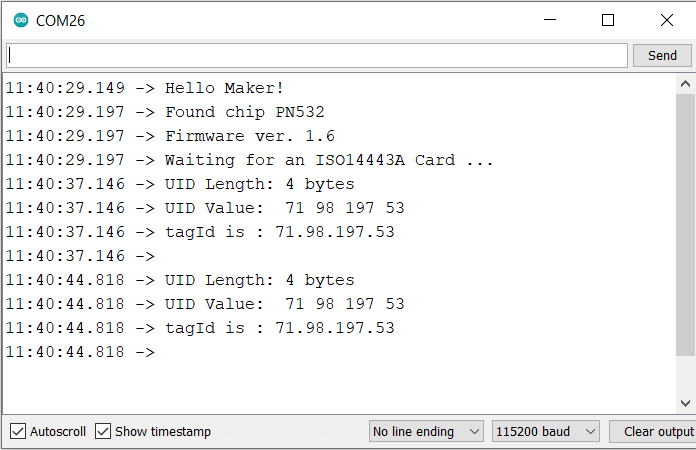
In the case of High-Speed UART mode, the chip was only able to read data with 4 bytes. The module fails in reading 7 bytes of data from NFC Cards.
Interfacing PN532 with Arduino in I2C Mode
Now let us read the NFC Data in I2C Mode. Connect the PN532 to Arduino as follows.

- GND (Ground) <-> GND
- VCC (Power supply) <-> 5V
- SDA (Data) <-> A4
- SCL (Clock) <-> A5

Source Code/Program
In the case of a I2C communication, download and add the PN532_I2C.h library to the library folder.
Copy the following code and upload it to the Arduino Board.
|
1 2 3 4 5 6 7 8 9 10 11 12 13 14 15 16 17 18 19 20 21 22 23 24 25 26 27 28 29 30 31 |
#include <Wire.h> #include <PN532_I2C.h> #include <PN532.h> #include <NfcAdapter.h> PN532_I2C pn532_i2c(Wire); NfcAdapter nfc = NfcAdapter(pn532_i2c); String tagId = "None"; byte nuidPICC[4]; void setup(void) { Serial.begin(115200); Serial.println("System initialized"); nfc.begin(); } void loop() { readNFC(); } void readNFC() { if (nfc.tagPresent()) { NfcTag tag = nfc.read(); tag.print(); tagId = tag.getUidString(); } delay(5000); } |
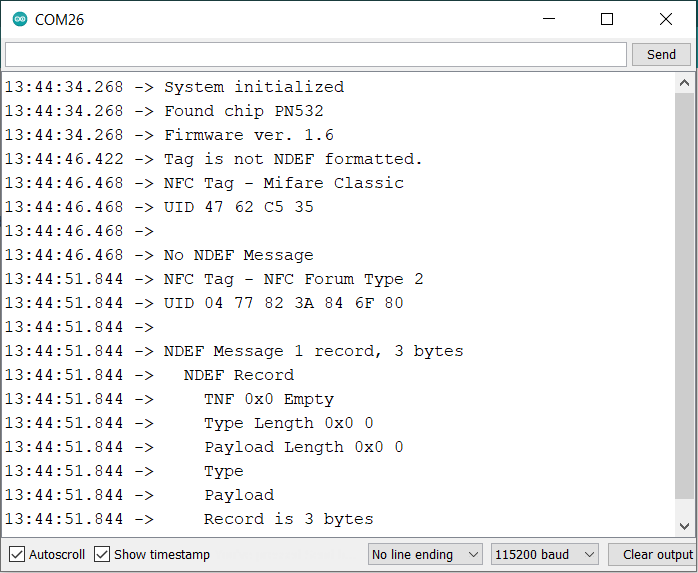
After uploading the code, you can open the Serial Monitor and start testing the module by bringing some NFC Cards near to the PN532. In I2C Mode, the chip is capable of reading both 4 bytes and 7 bytes of data from different NFC tags.

Interfacing PN532 with Arduino in SPI Mode
Now let us read the NFC Data in SPI Mode. In case of SPI mode there are too many connections. So, connect the PN532 to Arduino as follows.

- VCC (Power supply) <-> 5V
- RST (Reset) <-> 9
- GND (Ground) <-> GND
- MISO (Master Input Slave Output) <-> 11
- MOSI (Master Output Slave Input) <-> 12
- SCK (Serial Clock) <-> 13
- SS (Slave select) <-> 10

Source Code/Program
In the case of a SPI communication, download and add the PN532_SPI.h library to the library folder.
Copy the following code and upload it to the Arduino Board.
|
1 2 3 4 5 6 7 8 9 10 11 12 13 14 15 16 17 18 19 20 21 22 23 24 25 26 27 28 29 30 31 |
// for SPI Communication #include <SPI.h> #include <PN532_SPI.h> #include <PN532.h> #include <NfcAdapter.h> PN532_SPI interface(SPI, 10); // create a PN532 SPI interface with the SPI CS terminal located at digital pin 10 NfcAdapter nfc = NfcAdapter(interface); // create an NFC adapter object String tagId = "None"; void setup(void) { Serial.begin(115200); Serial.println("System initialized"); nfc.begin(); } void loop() { readNFC(); } void readNFC() { if (nfc.tagPresent()) { NfcTag tag = nfc.read(); tag.print(); tagId = tag.getUidString(); } delay(5000); } |
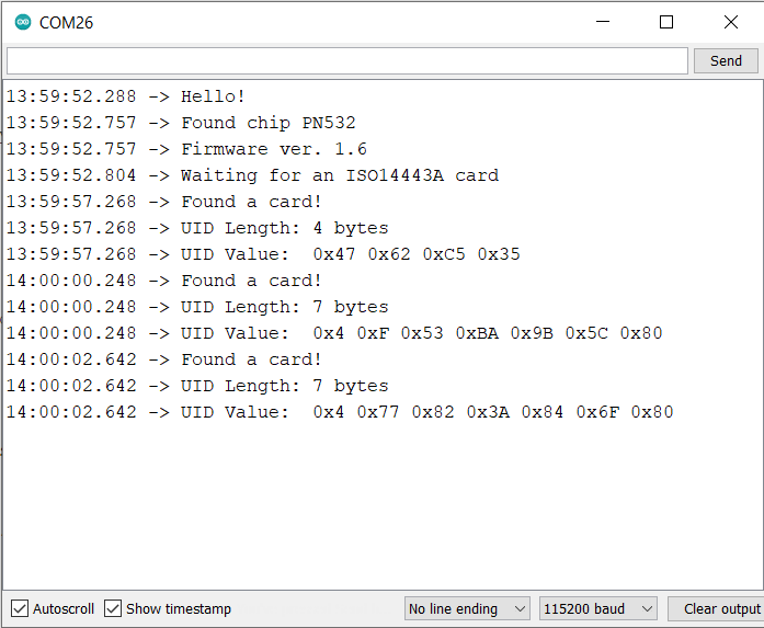
The 4 bytes and 7 bytes NFC Cards work well in this mode as well.
Making Portable NFC Scanner with OLED Display
We can make a portable NFC Scanner module using PN532 and Arduino Board. For displaying data we can add a 0.96″ I2C OLED Display to the below circuit.

Connect the PN532 Module & OLED Display to Arduino as per circuit diagram.
- GND (Ground) <-> GND
- VCC (Power supply) <-> 5V
- SDA (Data) <-> A4
- SCL (Clock) <-> A5
Source Code/Program
For this portable NFC Reader, we will not use the above library. Rather we will prefer latest Adafruit PN532 library. The library is written for Adafruit PN532 NFC/RFID breakout boards and work with Arduino UNO/Nano Board only in I2C or SPI Mode.
Apart from this we also need some other library for compilation. Download the following libraries and add them to the Arduino IDE via Library Manager:
1. Adafruit PN532 Library: Download
2. Adafruit GFX Library: https://github.com/adafruit/Adafruit-GFX-Library
3. SSD1306 OLED Library: Download
Copy the following code and upload it to your Arduino Board.
|
1 2 3 4 5 6 7 8 9 10 11 12 13 14 15 16 17 18 19 20 21 22 23 24 25 26 27 28 29 30 31 32 33 34 35 36 37 38 39 40 41 42 43 44 45 46 47 48 49 50 51 52 53 54 55 56 57 58 59 60 61 62 63 64 65 66 67 68 69 70 71 72 73 74 75 76 77 78 79 80 81 82 83 84 85 86 87 88 89 90 91 92 93 94 95 96 97 98 99 100 101 102 103 104 105 106 107 108 109 110 111 112 113 114 115 116 117 118 119 120 121 122 123 124 125 126 |
#include <Wire.h> #include <SPI.h> #include <Adafruit_GFX.h> #include <Adafruit_SSD1306.h> #include <Adafruit_PN532.h> #define PN532_IRQ (2) #define PN532_RESET (3) // Not connected by default on the NFC Shield #define SCREEN_WIDTH 128 // OLED display width, in pixels #define SCREEN_HEIGHT 64 // OLED display height, in pixels #define OLED_RESET 4 // Reset pin # (or -1 if sharing Arduino reset pin) #define SCREEN_ADDRESS 0x3C ///< See datasheet for Address; 0x3D for 128x64, 0x3C for 128x32; Adafruit_PN532 nfc(PN532_IRQ, PN532_RESET); Adafruit_SSD1306 display(SCREEN_WIDTH, SCREEN_HEIGHT, &Wire, OLED_RESET); void setup(void) { Serial.begin(115200); while (!Serial) delay(10); // for Leonardo/Micro/Zero Serial.println("Hello!"); nfc.begin(); if (!display.begin(SSD1306_SWITCHCAPVCC, SCREEN_ADDRESS)) { Serial.println(F("SSD1306 allocation failed")); for (;;); // Don't proceed, loop forever } uint32_t versiondata = nfc.getFirmwareVersion(); if (! versiondata) { Serial.print("Didn't find PN53x board"); while (1); // halt } // Got ok data, print it out! Serial.print("Found chip PN5"); Serial.println((versiondata>>24) & 0xFF, HEX); Serial.print("Firmware ver. "); Serial.print((versiondata>>16) & 0xFF, DEC); Serial.print('.'); Serial.println((versiondata>>8) & 0xFF, DEC); display.clearDisplay(); display.setCursor(0, 0); //oled display display.setTextSize(1); display.setTextColor(WHITE); display.print("Found chip PN5"); display.print((versiondata >> 24) & 0xFF, HEX); display.setCursor(0, 20); //oled display display.setTextSize(1); display.setTextColor(WHITE); display.print("Firmware ver. "); display.print((versiondata >> 16) & 0xFF, DEC); display.print("."); display.print((versiondata >> 8) & 0xFF, DEC); nfc.setPassiveActivationRetries(0xFF); // configure board to read RFID tags nfc.SAMConfig(); Serial.println("Waiting for an ISO14443A card"); display.setCursor(0, 40); //oled display display.setTextSize(1); display.setTextColor(WHITE); display.print("Waiting for NFC Card"); display.display(); } void loop(void) { boolean success; uint8_t uid[] = { 0, 0, 0, 0, 0, 0, 0 }; // Buffer to store the returned UID uint8_t uidLength; // Length of the UID (4 or 7 bytes depending on ISO14443A card type) success = nfc.readPassiveTargetID(PN532_MIFARE_ISO14443A, &uid[0], &uidLength); if (success) { Serial.println("Found a card!"); Serial.print("UID Length: "); Serial.print(uidLength, DEC); Serial.println(" bytes"); Serial.print("UID Value: "); display.clearDisplay(); display.setCursor(10, 0); //oled display display.setTextSize(1); display.setTextColor(WHITE); display.print("UID Length:"); display.print(uidLength, DEC); display.print(" bytes"); display.setCursor(35, 20); //oled display display.setTextSize(1); display.setTextColor(WHITE); display.println("UID Value: "); display.setCursor(5, 35); //oled display for (uint8_t i=0; i < uidLength; i++) { Serial.print(" 0x"); Serial.print(uid[i], HEX); display.print(" 0x"); display.print(uid[i], HEX); display.display(); } Serial.println(""); // Wait 1 second before continuing delay(1000); } else { // PN532 probably timed out waiting for a card Serial.println("Timed out waiting for a card"); } } |
After code uploads successfully, you can start the testing process. The OLED Display will print firmware version as 1.6 and will ask to scan the cards.

Now bring some NFC Cards near the PN532 NFC Board. The NFC Card may include your bank card or a travel card or maybe some NFC test Card. The PN532 Module will read byte length along with the UID value & displays them on the OLED screen.

Sometimes the byte length might be 4 bytes or 7 bytes depending upon the type of NFC Card.

In case you don’t want the OLED Display for the project, you can display the UID value and byte length on the Serial Monitor.
Video Tutorial & Guide

This is how we interface PN532 NFC RFID Module with Arduino in UART, I2C, and SPI Mode. A readymade NFC Module is available is market called as Maduino Zero NFC board that can be used for Payment, Entrance & Security System projects.

")


1 Comment
I have a doubt: the voltage on pins is 5V but on datasheet there is the max voltage on pins is PVDD and the mac voltage on pvdd is 3.6V, so PN532 has 5v tollerant pins?