

Overview
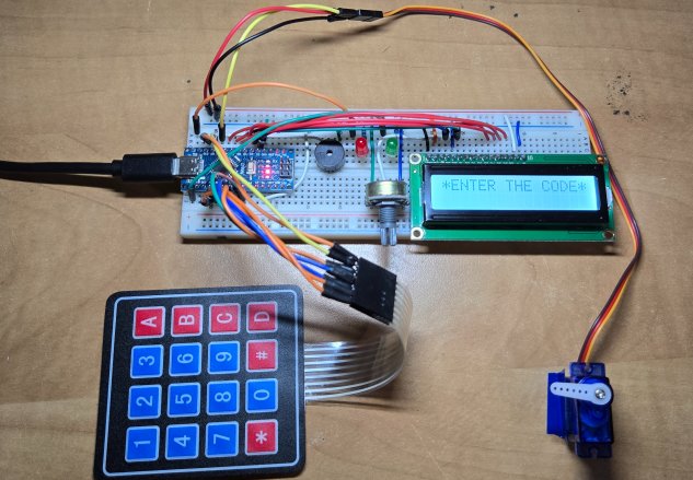
In this project, we will make a Password-Based Door Lock Security System using Arduino, a keypad, a servo motor, an LCD, and a buzzer. With rising concerns about security, this digital password-based lock can be an effective way to safeguard homes or lockers.
This system will unlock the door only when the correct password is entered. It’s a simple and effective way to keep your home or valuables safe. Earlier we built, RFID Security System and also Biometric Security Lock using Arduino.
In Password Based Door Lock Security System, the Arduino controls the whole system. The keypad is used to enter the password, and the LCD shows messages like “Enter Password” or “Access Granted.” The buzzer makes sounds to give feedback, like when a button is pressed or the password is wrong. If the correct password is entered, the servo motor unlocks the door and locks it again after a few seconds. This project is easy to build and very useful for security.
Bill of Materials
Follows are the list of components that you need for this project. You can purchase all these components from Amazon at affordable price.
| S.N. | Components | Quantity | Purchase Links |
|---|---|---|---|
| 1 | Arduino Nano Board | 1 | Amazon | AliExpress |
| 2 | 4x4 Keypad Matrix | 1 | Amazon | AliExpress |
| 3 | 16x2 LCD Display | 1 | Amazon | AliExpress |
| 4 | Potentiometer 10K | 1 | Amazon | AliExpress |
| 5 | SG90 Servo Motor | 1 | Amazon | AliExpress |
| 6 | Buzzer 5V | 1 | Amazon | AliExpress |
| 7 | LED Red | 1 | Amazon | AliExpress |
| 8 | LED Green | 1 | Amazon | AliExpress |
| 9 | Resistor 330 ohms | 2 | Amazon | AliExpress |
| 10 | Connecting Wires | 20 | Amazon | AliExpress |
| 11 | Breadboard | 1 | Amazon | AliExpress |
Circuit: Password Based Door Lock Security System using Arduino
The Password-Based Door Lock Security System uses an Arduino Nano, a 4×4 keypad, a servo motor, an LCD, LEDs, and a buzzer.

Below is an explanation of the connections:
- Arduino Nano: The Nano acts as the brain of the system. It processes inputs from the keypad, compares passwords, and controls the servo motor, LCD, LEDs, and buzzer.
- Keypad: The 4×4 keypad is used for entering passwords. It is connected to:
- Row Pins (A0, A1, A2, A3) of the Nano.
- Column Pins (A4, A5, 9, 10) of the Nano.
- Servo Motor: The servo motor is responsible for locking and unlocking the door. It is connected to pin 8 of the Nano. It receives commands from the Nano to rotate and unlock/lock the door.
- LCD (16×2): The LCD is used to display instructions and feedback messages like “Enter Password” or “Access Granted”. Its pins 1, 5, and 16 are connected to GND. The LCD pins 2 and 15 are connected to 5V of Arduino. A 10K potentiometer is connected to pin 3 of the LCD to control the LCD contrast. The data pins of the LCD are connected as follows:
- RS → pin 2
- E → pin 3
- D4 → pin 4
- D5 → pin 5
- D6 → pin 6
- D7 → pin 7
- Buzzer: The buzzer provides sound feedback for various actions like button presses, correct password, or incorrect password alerts. It is connected to pin 11 of the Nano.
- Red LED: The red LED indicates incorrect password attempts. It is connected to pin 12 with a 330-ohms current-limiting resistor.
- Green LED: The green LED indicates a successful password entry and access granted. It is connected to pin 13 with a 330-ohms current-limiting resistor.
The Arduino Nano is powered via USB or an external 5V supply. The components (servo, buzzer, LEDs) share a common ground with the Arduino Nano.
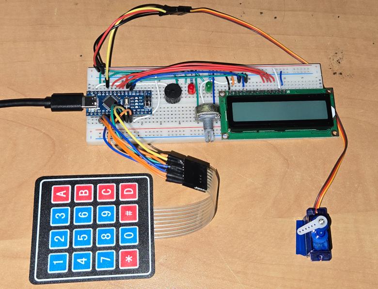
You can connect all the components on breadboard using jumper wires as per the circuit diagram above.
Source Code/Program
Here is the C++ Arduino code for our project. This code implements a Password-Based Door Lock System using an Arduino Nano, a 4×4 keypad, an LCD, a servo motor, a buzzer, and two LEDs.
The system allows users to set a password during the first boot, enter the password to unlock the door, and change the password by entering a master password. The keypad handles user input, while the LCD provides feedback such as “Enter Password” or “Access Granted.” The servo motor unlocks the door on a correct password, and the system relocks the door after a 10-second countdown.
The buzzer provides sound feedback for button presses, incorrect passwords, and access granted. The red LED indicates incorrect password attempts, while the green LED lights up on a successful password entry.
In the current code, the master password is set as “1234”. You may set your own Master password. The code also has a very well written comments which makes it very easy to understand each line of the code. Before uploading the code, please add the Keypad Library to the Arduino IDE to avoid compilation error.
Copy the following code and paste it on your Arduino IDE editor window.
|
1 2 3 4 5 6 7 8 9 10 11 12 13 14 15 16 17 18 19 20 21 22 23 24 25 26 27 28 29 30 31 32 33 34 35 36 37 38 39 40 41 42 43 44 45 46 47 48 49 50 51 52 53 54 55 56 57 58 59 60 61 62 63 64 65 66 67 68 69 70 71 72 73 74 75 76 77 78 79 80 81 82 83 84 85 86 87 88 89 90 91 92 93 94 95 96 97 98 99 100 101 102 103 104 105 106 107 108 109 110 111 112 113 114 115 116 117 118 119 120 121 122 123 124 125 126 127 128 129 130 131 132 133 134 135 136 137 138 139 140 141 142 143 144 145 146 147 148 149 150 151 152 153 154 155 156 157 158 159 160 161 162 163 164 165 166 167 168 169 170 171 172 173 174 175 176 177 178 179 180 181 182 183 184 185 186 187 188 189 190 191 192 193 194 195 196 197 198 199 200 201 202 203 204 205 206 207 208 209 210 211 212 213 214 215 216 217 218 219 220 221 222 223 224 225 226 227 228 229 230 231 232 233 234 235 236 237 238 239 240 241 242 243 244 245 246 247 248 249 250 251 252 253 254 255 256 257 258 259 260 261 262 263 264 265 266 267 268 |
#include <Keypad.h> #include <LiquidCrystal.h> #include <Servo.h> // Define pins for various components #define SERVO_PIN 8 // Servo motor pin #define RED_LED_PIN 12 // Red LED pin (for incorrect password indication) #define GREEN_LED_PIN 13 // Green LED pin (for access granted indication) #define BUZZER_PIN 11 // Buzzer pin (for sound feedback) Servo myservo; // Servo object LiquidCrystal lcd(2, 3, 4, 5, 6, 7); // LCD object with defined pins // Keypad configuration const byte rows = 4, cols = 4; // Keypad dimensions (4x4) char keys[rows][cols] = { // Keypad layout {'1', '2', '3', 'A'}, {'4', '5', '6', 'B'}, {'7', '8', '9', 'C'}, {'*', '0', '#', 'D'} }; byte rowPins[rows] = {A0, A1, A2, A3}; // Row pins connected to Arduino byte colPins[cols] = {A4, A5, 9, 10}; // Column pins connected to Arduino Keypad keypad = Keypad(makeKeymap(keys), rowPins, colPins, rows, cols); // Keypad object // Passwords char masterPassword[] = "1234"; // Master password for password change char savedPassword[5] = ""; // User-set password char enteredPassword[5]; // Buffer for entering a password int currentPosition = 0; // Tracks the number of entered digits int invalidCount = 0; // Counts incorrect password attempts // Flags for different modes bool isFirstBoot = true; // Indicates if it's the first time setting the password bool isSettingPassword = false; // Indicates if the system is in password setup mode bool isCheckingMaster = false; // Indicates if the system is verifying the master password void setup() { lcd.begin(16, 2); // Initialize LCD pinMode(RED_LED_PIN, OUTPUT); // Set LED pins as outputs pinMode(GREEN_LED_PIN, OUTPUT); pinMode(BUZZER_PIN, OUTPUT); // Set buzzer pin as output myservo.attach(SERVO_PIN); // Attach servo to the defined pin myservo.write(0); // Initial servo position (locked) Serial.begin(9600); // Begin serial communication (for debugging) // First boot behavior: prompt user to set the password if (isFirstBoot) { lcd.print("Set Password:"); // Show setup message on LCD isSettingPassword = true; // Enable password setup mode currentPosition = 0; // Reset the current position } else { lcd.print("*ENTER THE CODE*"); // Prompt user to enter the code } } void loop() { char key = keypad.getKey(); // Read key pressed on the keypad if (key) { playKeyPressSound(); // Play sound feedback for any key press if (isSettingPassword) { handlePasswordSetup(key); // Handle password setup mode } else if (isCheckingMaster) { handleMasterPasswordCheck(key); // Handle master password verification } else { handlePasswordEntry(key); // Handle normal password entry } } } // Function to play sound feedback for a key press void playKeyPressSound() { tone(BUZZER_PIN, 1000, 100); // Play 1kHz tone for 100ms delay(100); // Ensure sound is distinct } // Function to handle password setup void handlePasswordSetup(char key) { lcd.clear(); // Clear LCD for updated display if (key == 'B') { // Delete the last character if (currentPosition > 0) { currentPosition--; // Move back one position enteredPassword[currentPosition] = '\0'; // Clear the character } } else if (key >= '0' && key <= '9' && currentPosition < 4) { // Add digit to entered password if less than 4 digits enteredPassword[currentPosition] = key; currentPosition++; } else if (key == 'C') { // Confirm the entered password if (currentPosition == 4) { // Check if 4 digits are entered enteredPassword[4] = '\0'; // Null-terminate the string strncpy(savedPassword, enteredPassword, 5); // Save new password lcd.print("Password Set!"); // Display success message delay(2000); isSettingPassword = false; // Exit password setup mode isFirstBoot = false; // First boot completed lcd.clear(); lcd.print("*ENTER THE CODE*"); // Go back to normal mode currentPosition = 0; // Reset position for new entries } else { lcd.print("Incomplete Pass"); // Warn user of incomplete entry delay(2000); } return; } // Display entered digits during password setup lcd.setCursor(0, 0); lcd.print("Set New Pass:"); lcd.setCursor(0, 1); for (int i = 0; i < currentPosition; i++) { lcd.print(enteredPassword[i]); // Show the actual digits } } // Function to handle master password verification for password change void handleMasterPasswordCheck(char key) { lcd.clear(); // Clear LCD for updated display if (key == 'B') { // Delete the last character if (currentPosition > 0) { currentPosition--; // Move back one position enteredPassword[currentPosition] = '\0'; // Clear the character } } else if (key >= '0' && key <= '9' && currentPosition < 4) { // Add digit to entered password if less than 4 digits enteredPassword[currentPosition] = key; currentPosition++; } else if (key == 'C') { // Confirm the entered password if (currentPosition == 4) { // Check if 4 digits are entered enteredPassword[4] = '\0'; // Null-terminate the string if (strcmp(enteredPassword, masterPassword) == 0) { lcd.print("Master Verified"); // Display success message delay(2000); isCheckingMaster = false; // Exit master password check isSettingPassword = true; // Enter password setup mode currentPosition = 0; // Reset position for new entries lcd.clear(); lcd.print("Set Password:"); // Prompt to set new password } else { lcd.print("Incorrect Master"); // Display error message delay(2000); isCheckingMaster = false; // Exit master password check currentPosition = 0; // Reset position lcd.clear(); lcd.print("*ENTER THE CODE*"); // Go back to normal mode } } else { lcd.print("Incomplete Pass"); // Warn user of incomplete entry delay(2000); } return; } // Display asterisks during master password entry lcd.setCursor(0, 0); lcd.print("Master Pass:"); lcd.setCursor(0, 1); for (int i = 0; i < currentPosition; i++) { lcd.print("*"); // Show asterisks for entered digits } } // Function to handle normal password entry void handlePasswordEntry(char key) { if (key == 'A') { // Initiate password change lcd.clear(); lcd.print("Master Pass:"); currentPosition = 0; // Reset position isCheckingMaster = true; // Enter master password check mode return; } else if (key == 'B') { // Delete the last character if (currentPosition > 0) { currentPosition--; // Move back one position enteredPassword[currentPosition] = '\0'; // Clear the character } } else if (key >= '0' && key <= '9' && currentPosition < 4) { // Add digit to entered password if less than 4 digits enteredPassword[currentPosition] = key; currentPosition++; } else if (key == 'C') { // Confirm the entered password if (currentPosition == 4) { // Check if 4 digits are entered enteredPassword[4] = '\0'; // Null-terminate the string if (strcmp(enteredPassword, savedPassword) == 0) { unlockDoor(); // Unlock the door if password is correct } else { incorrectPassword(); // Indicate incorrect password } currentPosition = 0; // Reset position for new entries } else { lcd.clear(); lcd.print("Incomplete Pass"); // Warn user of incomplete entry delay(2000); lcd.clear(); lcd.print("*ENTER THE CODE*"); // Go back to normal mode } return; } // Display asterisks during normal password entry lcd.clear(); lcd.print("PASSWORD:"); lcd.setCursor(0, 1); for (int i = 0; i < currentPosition; i++) { lcd.print("*"); // Show asterisks for entered digits } } // Function to unlock the door void unlockDoor() { lcd.clear(); lcd.print("Access Granted"); digitalWrite(GREEN_LED_PIN, HIGH); // Turn on the green LED // Play success melody for (int i = 0; i < 4; i++) { tone(BUZZER_PIN, 400 + (i * 200), 200); delay(250); } noTone(BUZZER_PIN); digitalWrite(GREEN_LED_PIN, LOW); // Turn off the green LED delay(2500); // Display "Access Granted" for 2.5 seconds // Unlock the door and show countdown timer myservo.write(90); // Unlock position for (int secondsLeft = 10; secondsLeft > 0; secondsLeft--) { lcd.clear(); lcd.print("Door locks in:"); lcd.setCursor(6, 1); lcd.print(secondsLeft); // Show countdown timer lcd.print(" sec"); delay(1000); } // Lock the door lcd.clear(); lcd.print("Locking Door..."); myservo.write(0); // Lock position delay(1000); lcd.clear(); lcd.print("*ENTER THE CODE*"); // Go back to normal mode } // Function to handle incorrect password entry void incorrectPassword() { lcd.clear(); lcd.print("CODE INCORRECT"); digitalWrite(RED_LED_PIN, HIGH); // Turn on the red LED // Play alert melody for (int i = 0; i < 3; i++) { tone(BUZZER_PIN, 300, 150); delay(200); tone(BUZZER_PIN, 100, 150); delay(200); } noTone(BUZZER_PIN); digitalWrite(RED_LED_PIN, LOW); // Turn off the red LED delay(2500); // Display "CODE INCORRECT" for 2.5 seconds lcd.clear(); lcd.print("*ENTER THE CODE*"); // Go back to normal mode } |
From the tools Menu, select the Arduino Nano Board. Then Select the COM port and hit the upload button to upload the code. The code will be uploaded.
Testing: Password Based Security System Using Arduino & Keypad
After uploading is done, now the device is ready for the test. Go through the following instructions to set the password or lock/unlock the door or to change the password.
The keys A, B, and C on the keypad have the following functions:
- Key A:
- Used to initiate the password change process.
- When pressed, it prompts the user to enter the master password. If the master password is correct, the user is allowed to set a new password. If incorrect, it displays “Incorrect Master” and returns to normal mode.
- Key B:
- Functions as a backspace/delete key.
- If pressed during password entry or setup, it deletes the last entered digit, allowing the user to correct typing errors.
- Key C:
- Used to confirm the entered password.
- During normal operation, it checks the entered password against the saved password. If the passwords match, the door unlocks. During password setup, it confirms the newly entered password and saves it.
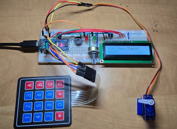
Setting the Password
Initially, when the device boots up, it will ask you to set up the password.
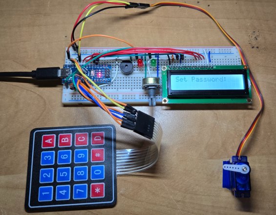
Use the keypad to enter the 4 digit code. The code can be anything from “0000” to “9999”.
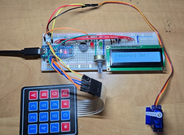
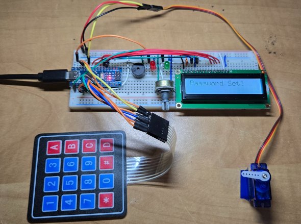
Press button C to enter or to set password. The password will be set successfully.
Unlocking/Locking the Door
Once the password is set, you can start unlocking the door by entering the right password.
Use the keypad to enter the 4-digit password. Press the C key to enter.
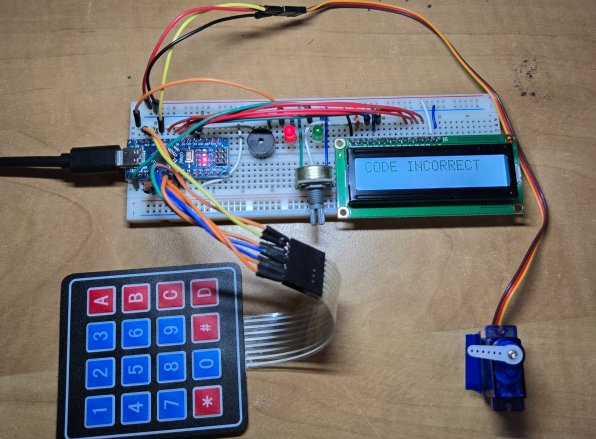
If the password entered is wrong, the LCD will show “CODE INCORRECT”. The Red LED will turn ON and Buzzer will melody.
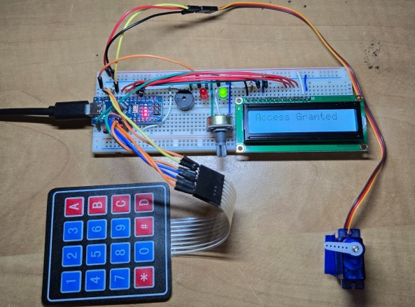
If the password entered is correct, the LCD will show “Access Granted”. The green LED will turn ON and Buzzer will play a melody.
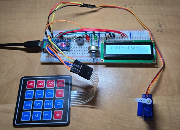
At the same time, Servo Motor will rotate and open the door. It will display a 10-second timer as well before it closes the door again.
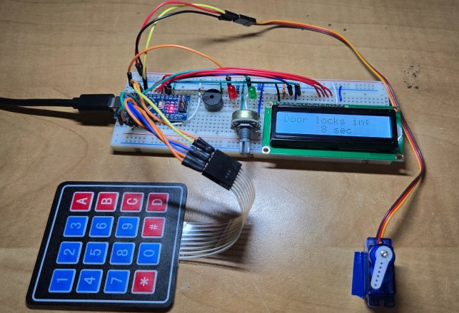
Once the 10-second timer is gone, the door will close again.
Changing the Password
If you want to change the password, press the button A. Then it will ask you to enter the master password.
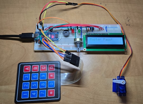
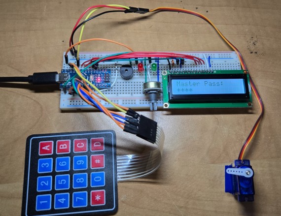
The default Master Password is “1234”, which is set in the code. You may modify your code to change the default master password. Enter the password using the keypad and press button C.
If the master password is correct, it will show “Master Verified” message on LCD screen.
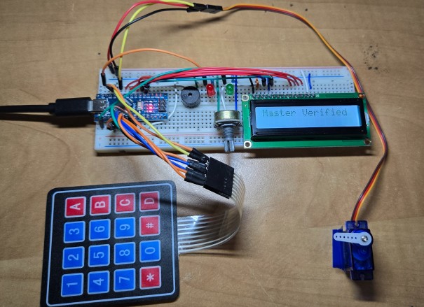
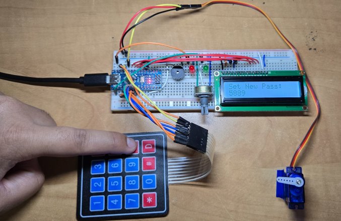
Now you can set the New password here. The LCD will ask you to Set the new password.
Enter 4 digit New password and press C button again.
Now you are ready to test it again. You can enter the code to unlock the door again.
Video Tutorial & Guide


")


24 Comments
What happens if the key pad fails or if someone forgets password
The door won’t open simply.
What if after locking battery gets dead?
You dc power supply from adapter
Is their any solution for above mentioned problems
i want to detect coin, when i put the coin in loadcell…after i put 1 more coin, the system detect total nominal of all coins…for example coin 100(2 grams)+ 200(3 grams)= 300(5 grams)…can you help me with my project??
thank you very much,,,
can i use 4×4 keypad instead of 3×4??
yes, you can. modification in code is required too
WHAT IS TORTURE 1 & 2 ??
Can’t find the library file keypad.h for downlaod
can’t find the library file keypad.h for download
sir
I need simple Eletronice cabinet doors lock keypad password control circuits digram or P. C.B perches give me ida’s
Thanks
Sir LCD not work.. plzs help me?
Hey dude. The Keypad.h library is not available anymore on that link. Can you share some other link where it can be downloaded? Thanks!
the servo is moving before the password is entered
YES PLEASE TELL ME WHAT IS PROBLEM I AM USING 4*4 KEYPAD THARE 1,2,3,A,B,C,D button will not work please resolve my problem as soon as possible
Why keypress and unlock door function are not coming on my IDE
Any body can need this project plese call me 8401016135
thank you
it is not a build in function we have to define
f (code==password[currentposition])
{
++currentposition;
if(currentposition==4)
{
unlockdoor();
currentposition=0;
}
}
else
{
++invalidcount;
incorrect();
currentposition=0;///////////////////////////////////////////
}
if(invalidcount==5)
{
++invalidcount;
torture1();
}
if(invalidcount==8)
{
torture2();
}
}
anyone explain what happing here exactly
SIR I WANT TO INTERFACE IT WITH LM35 SENSOR….MEANS THAT IF A CERTAIN TEMPERATURE IS SET THEN ONLY THE PASSWORD IS ENTERED OTHERWISE NOT….
SIR PLEASE HELP ME WITH THIS….ITS VERY IMPORTANT……
How can i add a pushbutton code to open the servo in this program
can you use a ESP32 too?
I believe the code order is incorrect. She put the loop function before declaring the code within the loop. the loop should be at the end.
void loop() {
char key = keypad.getKey(); // Read key pressed on the keypad
if (key) {
playKeyPressSound(); // Play sound feedback for any key press
if (isSettingPassword) {
handlePasswordSetup(key); // Handle password setup mode
} else if (isCheckingMaster) {
handleMasterPasswordCheck(key); // Handle master password verification
} else {
handlePasswordEntry(key); // Handle normal password entry
}
}
}