

Overview
In this tutorial, we will explore the CAN Bus communication protocol by interfacing the MCP2515 CAN Bus Module with ESP32 microcontroller. Our objective is to transmit data from a DS18B20 temperature sensor over a specified distance using the CAN protocol. In earlier tutorial, we used MCP2515 with Arduino for CAN Bus communication.
The Controller Area Network (CAN) Bus is widely used in industrial settings and automotive diagnostics due to its ability to cover long distances, moderate communication speed, and high reliability. The standard protocols like UART, SPI, and I2C are less reliable over long distances. But CAN is ideal for vehicular systems and environments where communication occurs over extensive wiring. CAN communication typically supports speeds ranging from 50 Kbps to 1 Mbps and can maintain signal integrity over distances from 40 meters at 1 Mbps to up to 1000 meters at 50 Kbps.
We will use a pair of ESP32 boards and MCP2515 modules to demonstrate the transmission of DS18B20 temperature sensor data. The transmitted data will be received by receiver over and is displayed on OLED Display. Let’s get started with today’s guide on CAN Bus communication using the Microchip MCP2515 CAN Bus Module.
Bill of Materials
Here are the list of components that you need for this tutorial
| S.N. | Components | Quantity | |
|---|---|---|---|
| 1 | ESP32 Board | 2 | Amazon | AliExpress |
| 2 | CAN Module MCP2515 | 2 | Amazon | AliExpress |
| 3 | OLED Display | 1 | Amazon | AliExpress |
| 4 | DS18B20 Temperature Sensor | 1 | Amazon | AliExpress |
| 5 | Resistor 4.7K | 1 | Amazon | AliExpress |
| 6 | Jumper Wires | 30 | Amazon | AliExpress |
| 7 | Breadboard | 2 | Amazon | AliExpress |
MCP2515 CAN Bus Controller Module
The MCP2515 CAN Bus Controller is a simple Module that supports CAN Protocol version 2.0B and can be used for communication at 1Mbps.

This particular module is based on MCP2515 CAN Controller IC and TJA1050 CAN Transceiver IC. The MCP2515 IC is a standalone CAN Controller and has an integrated SPI Interface for communication with microcontrollers. Coming to the TJA1050 IC, it acts as an interface between the MCP2515 CAN Controller IC and the Physical CAN Bus.

The board has a 8 MHz Crystal oscillator. Even the 16 MHz version is also available. A jumper can be attached which will give 120ohm Termination. CAN_H & CAN_L are the two screws where wires can be attached over a distance for communicating with other CAN Module.
Following is the schematic of MCP2515 CAN Module.

MCP2515 IC is the main controller that internally consists of three main subcomponents: The CAN Module, the Control Logic, and the SPI Block. CAN Module is responsible for transmitting and receiving messages on the CAN Bus. Control Logic handles the setup and operation of the MCP2515 by interfacing all the blocks. The SPI Block is responsible for the SPI communication interface. The TJA1050 IC IC is responsible for taking the data from the controller and relaying it onto the bus.
Features and Specification of MCP2515
- Uses High-speed CAN transceiver TJA1050
- Dimension: 40×28mm
- SPI control for expanding Multi CAN bus interface
- 8MHZ crystal oscillator
- 120Ω terminal resistance
- Has independent key, LED indicator, Power indicator
- Supports 1 Mb/s CAN operation
- Low current standby operation
- Up to 112 nodes can be connected
For more information refer to MCP2515 Datasheet which also has a detailed guide.
Interfacing MCP2515 CAN Bus Module with ESP32
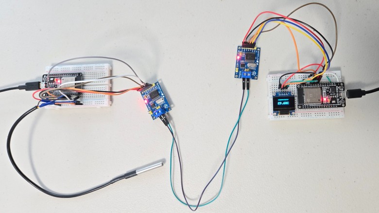
Now let us interface MCP2515 CAN Bus Module with ESP32 Board and test the CAN Communication protocol. We will transmit the DS18B20 Waterproof Temperature Sensor data over a CAN Bus with the help of pair of ESP32 Board & MCP2515 CAN Module. Here is the simple connection diagram.

The left part consisting of ESP32 Board, MCP2515 CAN Module & DS18B20 Sensor is a transmitter part.
Similarly, the right part consisting of ESP32 Board, MCP2515 CAN Module & OLED Display is the receiver part.
The transmitter & Receiver Part is connected to each other with the help of the MCP2515 CAN Bus Module. The CAN_H & CAN_L of the transmitter are connected to the CAN_H & CAN_L of the receiver respectively.

The connection between ESP32 Board & MCP2515 CAN Module is as follows.
| MCP2515 Pin | ESP32 Pin |
| VCC | 5V |
| GND | GND |
| CS | IO5 |
| SO | IO19 |
| SI | IO23 |
| SCK | IO13 |
| INT | IO4 |
On the transmitter part, the DS18B20 Sensor pin is connected to ESP32 IO21 Pin. The DS18B20 Sensor output is connected to VCC via 4.7K resistor.

On the receiver part, the I2C OLED Display has 4 pins & VCC, GND, SCL, and SDA. The SCL & SDA are I2C Pins that are connected to the IO22 & IO21 of the ESP32 Board. The VCC & GND of OLED connects to the 3.3V & GND of Arduino.

You can assemble the circuit on a breadboard or you can use your own custom PCB for this project.
Source Code/Program for ESP32 MCP2515 CAN Communication
Before moving to the coding part of the project, we need to install MCP2515 CAN Bus Library to the Arduino IDE. Download the library from the following link and then add it to the Arduino Library folder.
This CAN-BUS library gives your ESP32 CAN-BUS capability with the following features.
- Implements CAN V2.0B at up to 1 Mb/s
- SPI Interface up to 10 MHz
- Standard (11 bit) and extended (29 bit) data and remote frames
- Two receive buffers with prioritized message storage
You also need to add OneWire Library as well as Dallas Temperature Library for DS18B20 Temperature sensor.
The code is divided into two parts one as CAN transmitter code and the other as CAN Receiver code.
ESP32 CAN Transmitter Code
|
1 2 3 4 5 6 7 8 9 10 11 12 13 14 15 16 17 18 19 20 21 22 23 24 25 26 27 28 29 30 31 32 33 34 35 36 37 38 39 40 41 42 43 44 45 46 47 48 49 50 51 52 53 54 55 56 57 58 59 60 61 62 63 64 65 66 67 68 69 70 71 72 73 74 75 76 77 |
#include <OneWire.h> #include <DallasTemperature.h> #include <SPI.h> #include <mcp2515.h> #define ONE_WIRE_BUS 21 // GPIO where the DS18B20 is connected OneWire oneWire(ONE_WIRE_BUS); DallasTemperature sensors(&oneWire); struct can_frame canMsg; struct MCP2515 mcp2515(5); // CS pin is GPIO 5 #define MAX_RETRIES 3 #define CAN_ACK_ID 0x037 // CAN ID for acknowledgment void setup() { Serial.begin(115200); SPI.begin(); mcp2515.reset(); mcp2515.setBitrate(CAN_500KBPS, MCP_8MHZ); mcp2515.setNormalMode(); sensors.begin(); } void loop() { sensors.requestTemperatures(); float temperatureC = sensors.getTempCByIndex(0); int tempInt = (int)(temperatureC * 100); // Convert temperature to integer for transmission // Prepare CAN message canMsg.can_id = 0x036; // CAN ID canMsg.can_dlc = 2; // Data length code (number of bytes) canMsg.data[0] = (tempInt >> 8) & 0xFF; // MSB of temperature canMsg.data[1] = tempInt & 0xFF; // LSB of temperature bool messageSent = false; int retries = 0; while (!messageSent && retries < MAX_RETRIES) { if (mcp2515.sendMessage(&canMsg) == MCP2515::ERROR_OK) { Serial.print("Temperature sent: "); Serial.print(temperatureC); Serial.println(" °C"); // Wait for acknowledgment unsigned long startTime = millis(); bool ackReceived = false; while (millis() - startTime < 500) { // Wait up to 500ms for an ACK if (mcp2515.readMessage(&canMsg) == MCP2515::ERROR_OK) { if (canMsg.can_id == CAN_ACK_ID) { ackReceived = true; break; } } } if (ackReceived) { Serial.println("ACK received"); messageSent = true; } else { Serial.println("ACK not received, retrying..."); retries++; } } else { Serial.println("Error sending message, retrying..."); retries++; } } if (!messageSent) { Serial.println("Failed to send message after retries"); } delay(1000); // Send data every second } |
ESP32 CAN Receiver Code
|
1 2 3 4 5 6 7 8 9 10 11 12 13 14 15 16 17 18 19 20 21 22 23 24 25 26 27 28 29 30 31 32 33 34 35 36 37 38 39 40 41 42 43 44 45 46 47 48 49 50 51 52 53 54 55 56 57 58 59 60 61 62 63 64 |
#include <SPI.h> #include <mcp2515.h> #include <Adafruit_SSD1306.h> #define SCREEN_WIDTH 128 #define SCREEN_HEIGHT 64 #define OLED_RESET -1 Adafruit_SSD1306 display(SCREEN_WIDTH, SCREEN_HEIGHT, &Wire, OLED_RESET); struct can_frame canMsg; struct MCP2515 mcp2515(5); // CS pin is GPIO 5 #define CAN_ACK_ID 0x037 // CAN ID for acknowledgment void setup() { Serial.begin(115200); display.begin(SSD1306_SWITCHCAPVCC, 0x3C); display.clearDisplay(); display.setTextColor(WHITE); SPI.begin(); mcp2515.reset(); mcp2515.setBitrate(CAN_500KBPS, MCP_8MHZ); mcp2515.setNormalMode(); } void loop() { if (mcp2515.readMessage(&canMsg) == MCP2515::ERROR_OK) { if (canMsg.can_id == 0x036) // Check if the message is from the sender { int tempInt = (canMsg.data[0] << 8) | canMsg.data[1]; // Combine MSB and LSB float temperatureC = tempInt / 100.0; // Convert back to float Serial.print("Temperature received: "); Serial.print(temperatureC); Serial.println(" °C"); display.clearDisplay(); display.setTextSize(1); display.setCursor(25, 10); display.print("Temperature:"); display.setTextSize(2); display.setCursor(25, 30); display.print(temperatureC); display.print("C"); display.display(); // Send acknowledgment canMsg.can_id = CAN_ACK_ID; // Use ACK ID canMsg.can_dlc = 0; // No data needed for ACK mcp2515.sendMessage(&canMsg); Serial.println("ACK sent"); } } } |
Code Explanation
A canMsg struct data type for storing CAN message format.
|
1 |
struct can_frame canMsg; |
It set the pin number where SPI CS is connected.
|
1 |
MCP2515 mcp2515(5); |
The MCP2515 is being RESET using the following command.
|
1 |
mcp2515.reset(); |
The MCP2515 is set to a speed of 500KBPS and 8MHZ as the clock frequency.
|
1 |
mcp2515.setBitrate(CAN_500KBPS,MCP_8MHZ); |
The MCP2525 is set at normal mode.
|
1 |
mcp2515.setNormalMode(); |
The CAN ID is given as 0x036 and DLC as 2 and we define temperature data to the data[0] and data[1] and reset all data with 0. The DLC represents the Data Length Code, indicating the number of bytes being transmitted in the message. In this case, it’s 2 for the temperature data.
|
1 2 3 4 |
canMsg.can_id = 0x036; // CAN ID canMsg.can_dlc = 2; // Data length code (number of bytes) canMsg.data[0] = (tempInt >> 8) & 0xFF; // MSB of temperature canMsg.data[1] = tempInt & 0xFF; // LSB of temperature; |
In order to send the message to CAN BUS we use the following statement.
|
1 2 3 4 5 6 7 8 |
while (millis() - startTime < 500) { // Wait up to 500ms for an ACK if (mcp2515.readMessage(&canMsg) == MCP2515::ERROR_OK) { if (canMsg.can_id == CAN_ACK_ID) { ackReceived = true; break; } } } |
The sender attempts to resend the message up to MAX_RETRIES times if an acknowledgment is not received within 500 milliseconds. This helps ensure the message is reliably delivered.
|
1 2 3 4 5 6 7 8 9 10 11 |
if (ackReceived) { Serial.println("ACK received"); messageSent = true; } else { Serial.println("ACK not received, retrying..."); retries++; } } else { Serial.println("Error sending message, retrying..."); retries++; } |
This statement is used to receive the message from the CAN bus. If the message is received it gets into the if condition.
|
1 |
if (mcp2515.readMessage(&canMsg) == MCP2515::ERROR_OK) |
If the sender fails to send the message after the allowed number of retries, it prints an error message to the Serial Monitor. This helps in diagnosing communication issues.
Testing ESP32 MCP2515 CAN Bus Communication
Upload both of these codes to the respective ESP32 Boards. From Tools Menu, Select ESP32 Dev Module. Then Select COM port. Then upload the code.
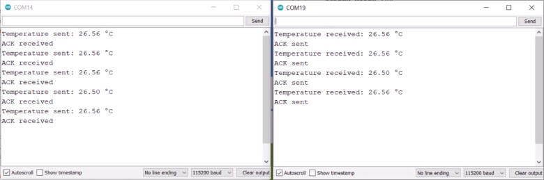
After uploading the code, when the board is powered you should notice the temperature value read by DS18B20 will be sent to another ESP32 through CAN communication.
The message will be displayed on the OLED of the 2nd ESP32.

You may also open the Serial Monitor and check the same transmitter and receiver message.
Remember, you may need to short a 120 ohm resistor at receiver MCP2515 Board. Else if not shorted, sometimes the OLED may appear blank as no message is received. This is how you can use the CAN Bus communication with ESP32.


1 Comment
If the MCP2515 Vcc is connected to 5V the pins SI, SO and SCK will have a 5V logic. The Esp32 can handle only 3.3V at it pins. Won’t the MCP2515 damage the Esp32?