

Overview
In this project, we develop an ESP32-based IoT Vehicle Motion Analyzer that monitors and analyzes driving behavior using motion sensors. The system utilizes the MPU6050 accelerometer and gyroscope along with the LIS3MDL magnetometer to measure vehicle movement, orientation, and directional heading in real time.
The MPU6050 sensor provides acceleration and angular velocity data, enabling the detection of events such as rapid acceleration, harsh braking, and sharp turns. Meanwhile, the LIS3MDL magnetometer acts as a digital compass, helping determine the vehicle’s heading and improving motion analysis by providing directional information.
An ESP32 microcontroller processes the sensor data and identifies driving patterns. The device displays key motion parameters such as forward acceleration, lateral acceleration, yaw rate, and heading on an OLED display. In addition, the system features a Wi-Fi enabled web interface, allowing users to monitor vehicle motion in real time from a smartphone.
The analyzer also includes a data logging system, enabling users to start and stop logging sessions and download the recorded motion data in CSV format for further analysis.
Block Diagram of ESP32 Vehicle Motion Analyzer
The block diagram of the ESP32 Vehicle Motion Analyzer shows how the main components interact to monitor vehicle motion.
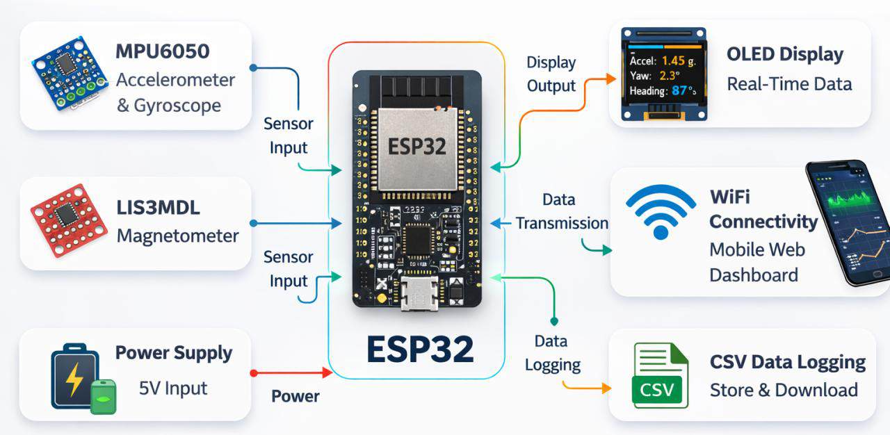
At the center is the ESP32 microcontroller, which acts as the main processing unit. It receives motion data from two sensors: the MPU6050 (accelerometer and gyroscope) and the LIS3MDL magnetometer. These sensors communicate with the ESP32 through the I²C interface, allowing the controller to collect and process real-time motion information.
The processed data is displayed on an OLED screen for real-time viewing. The ESP32 also uses its built-in Wi-Fi connectivity to send the data to a mobile web dashboard, enabling remote monitoring through a smartphone. In addition, the system supports CSV data logging, allowing motion data to be stored and downloaded later for analysis. All components are powered by a power supply module, which provides the required energy for the system to operate.
Circuit Diagram & Schematic Details
Let’s take a look at the circuit diagram of this project. The circuit consists of multiple sections, including the power supply, switches, battery charger, buck converters, sensors, ESP32 microcontroller, and OLED display, along with many other active and passive components required for proper system operation.
Each section plays an important role in powering the device, processing sensor data, and displaying and transmitting the vehicle motion information. Let us learn about them in detail. You can download the complete schematic file from here:
BQ24092 Battery Charger
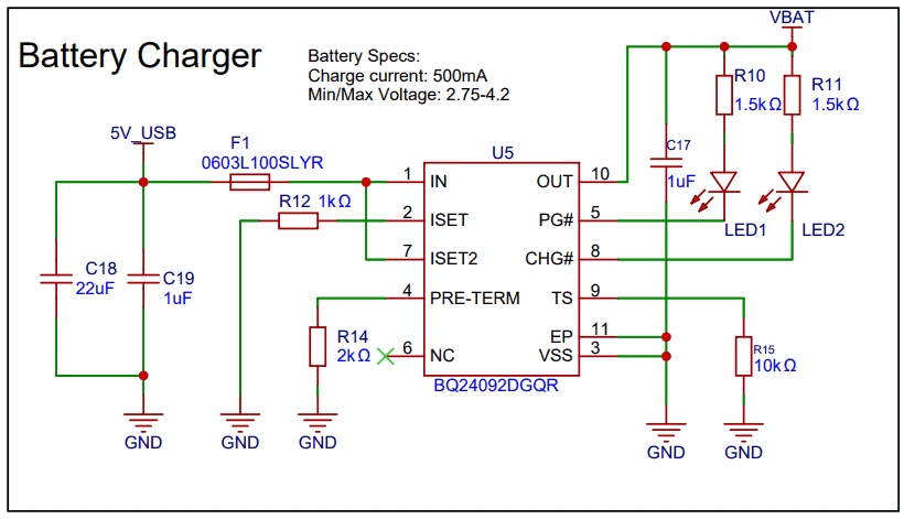
This section of the circuit is used for charging the battery using the BQ24092 battery charger IC. The 5V USB input provides power, which is filtered by capacitors and protected by a fuse. The charging current is set to 500 mA using a resistor connected to the ISET pin.
The IC automatically controls the charging process for the Li-ion battery. LED1 and LED2 indicate the charging status and power status. Other components like resistors and capacitors help ensure stable and proper operation of the charger circuit.
USB-to-UART (CP2104)
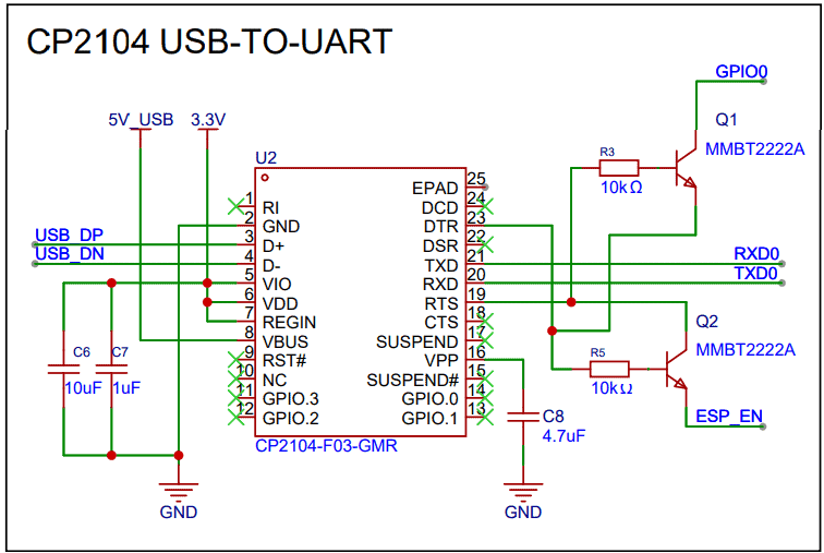
This section uses the CP2104 USB-to-UART converter to communicate between the computer and the ESP32. The USB data lines (D+ and D−) connect to the CP2104, which converts USB signals to UART signals (TXD and RXD) for programming and debugging the ESP32. Transistors Q1 and Q2 automatically control the boot and reset pins, allowing the ESP32 to enter programming mode during firmware upload.
Battery Sensing
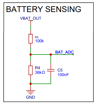
This circuit is used to measure the battery voltage using the ESP32’s ADC. Resistors R2 and R4 form a voltage divider that scales down the battery voltage to a safe level for the ESP32 ADC pin (BAT_ADC). Capacitor C5 filters noise to provide a stable voltage reading.
ESP32 MCU
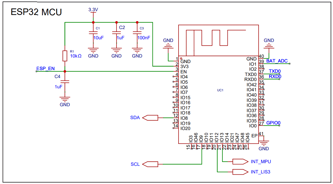
The ESP32-S3 microcontroller is the main controller of the system. It reads data from sensors, processes the vehicle motion information, and communicates with the OLED display and web dashboard. The SDA and SCL pins are used for I²C communication, while other pins handle serial communication, battery sensing, and sensor interrupts.
Buck-Boost Converter (3.3V)
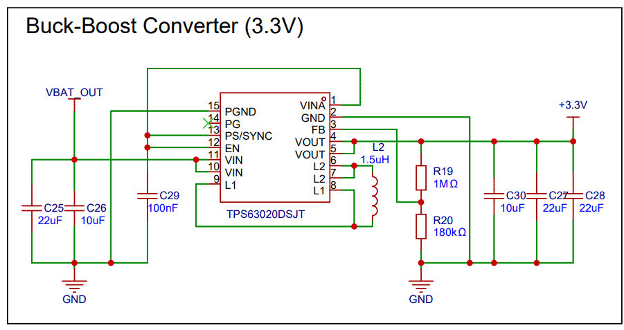
This section generates a stable 3.3V supply for the system using the TPS63020 buck-boost converter. It can step the battery voltage up or down to maintain a constant 3.3V output. Inductor L2, resistors, and capacitors help regulate and filter the power supply.
USB-C Connector
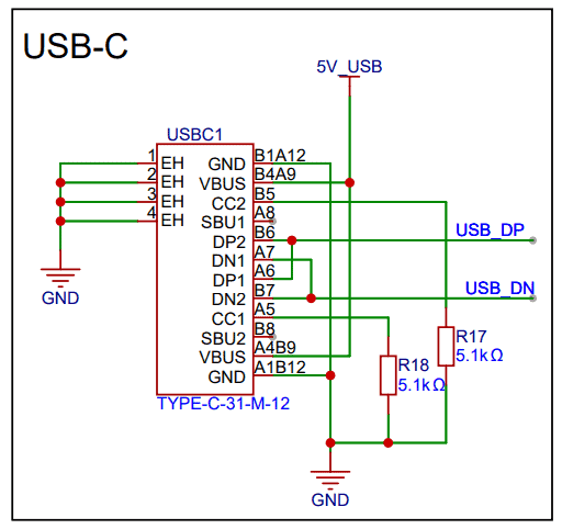
The USB-C port provides 5V power and USB data connectivity. It allows the device to be powered from USB and enables communication with the CP2104 USB-to-UART converter. Resistors are used to properly configure the USB-C interface. Using this the battery can be charged as well
Battery Section
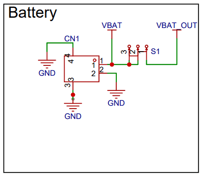
This section connects the Li-ion battery to the circuit. The battery provides the main power source for the system. A switch (S1) is used to turn the device on or off by controlling the battery output (VBAT_OUT).
MPU6050 (Accelerometer + Gyroscope)
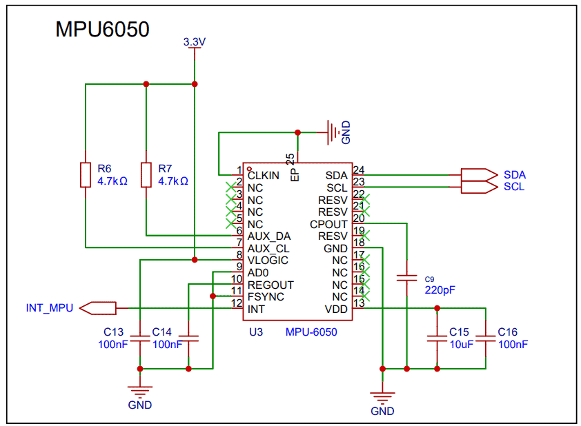
This section uses the MPU6050 motion sensor, which contains a 3-axis accelerometer and 3-axis gyroscope. It measures the vehicle’s acceleration and rotational movement. The sensor communicates with the ESP32 through the I²C interface (SDA and SCL). Capacitors are used for power filtering, and the INT pin sends an interrupt signal (INT_MPU) to the ESP32 when new sensor data is available.
LIS3MDL (Magnetometer)
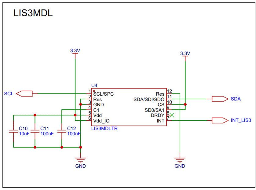
This section uses the LIS3MDL magnetometer, which measures the Earth’s magnetic field to determine the heading or direction of the vehicle. It also communicates with the ESP32 using the I²C bus (SDA and SCL). Capacitors help stabilize the power supply, and the INT pin (INT_LIS3) notifies the ESP32 when new magnetic data is ready.
I²C Pull-Up Resistors
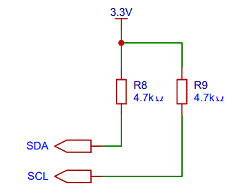
Resistors R8 and R9 (4.7kΩ) are used as pull-up resistors for the SDA and SCL lines of the I²C communication bus. These resistors ensure proper signal levels and reliable communication between the ESP32, MPU6050, LIS3MDL, and OLED.
OLED Display (0.96″)
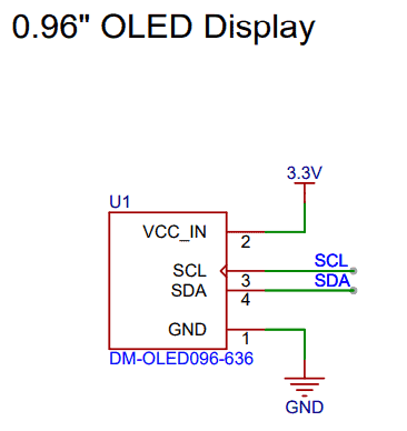
This section shows the 0.96-inch OLED display, which is used to show real-time vehicle motion data such as heading, acceleration, and turning information. The display operates on 3.3V power and communicates with the ESP32 using the I²C interface (SDA and SCL).
PCB Designing & Gerber Files
Based on the schematic shown above, a 4-layer PCB was designed for this project. The top layer contains all the components required for assembly. The first inner layer is used as a ground (GND) plane, while the second inner layer is dedicated to signal routing. Additional routing is also performed on the top and bottom layers.
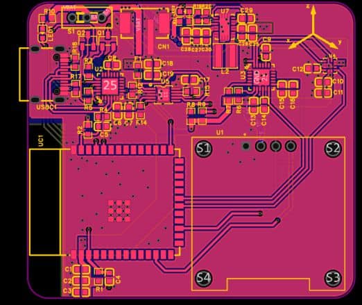
Proper ground connections are maintained between all layers to ensure a solid ground plane, which helps reduce noise and electromagnetic interference. This improves signal integrity and ensures reliable operation of the circuit.
Here is the 3D view of the PCB, showing all the components assembled on the top side of the board. This view provides a clear visualization of the component placement and overall layout of the circuit.
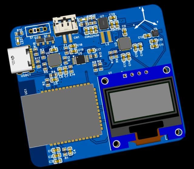
Here are the link of files that you can download for PCB manufacturing and PCB assembly services.
PCB Ordering Online & Assembly
The Gerber file for this ESP32 Vehicle Motion Analyzer is provided above. You can download the Gerber file and place an order with a PCB manufacturer like ALLPCB for as low as $1.
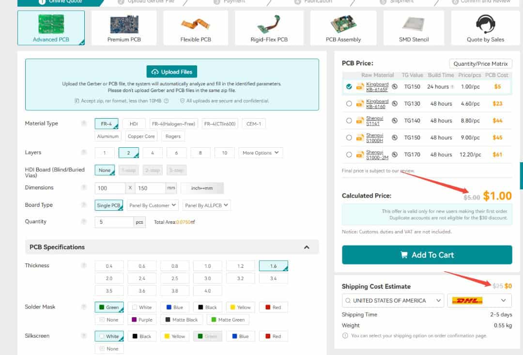
To order the PCB, visit the ALLPCB Official Website and upload the Gerber file using the Quote Now option. You can then choose your required parameters, such as Material Type, Dimensions, Quantity, Thickness, and Solder Mask Color.
ALLPCB is making PCB prototyping more affordable for new users by offering $30 off your first PCB order, plus $30 off shipping. With this promotion, you can enjoy free shipping on your first order—no restrictions on size, layers, or quantity.
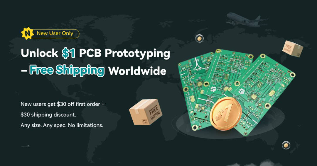
Here is the campaign detail: Unlock $1 PCB Prototyping
Once all the details are filled in, select your country and shipping method. After confirming everything, you can place the order and wait for your boards to arrive.
Finally, after receiving the PCB, you can assemble the SMD components and the ESP32 module on the board.
Assembly & Testing the ESP32 Vehicle Motion Analyzer Board
After one week, I received the PCB box from ALLPCB.
The box contained the PCB as expected. The quality was super fine and I could finally use it make my ESP32 Vehicle Motion Analyzer.
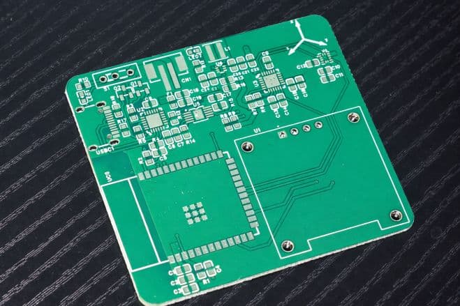
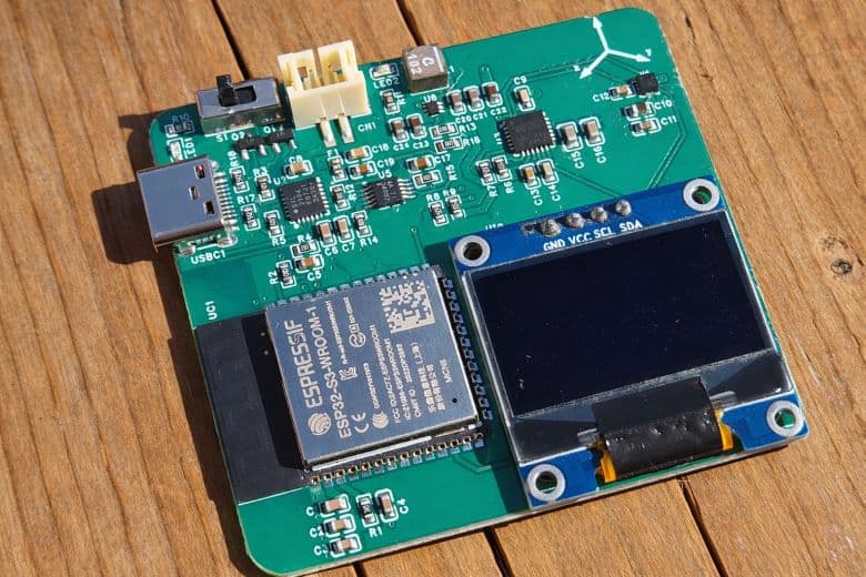
After receiving the PCB from ALLPCB, you can begin by soldering all the SMD components on the front side of the board.
The layout has been kept compact, and only the front side contains the ESP32 module, buck-boost converter, battery charging IC, resistors, and capacitors.
During the first revision, there were only a few minor issues with capacitor and resistor values, but these have been corrected in the final Gerber files. You can safely order and assemble the board directly using the updated files without any footprint concerns.
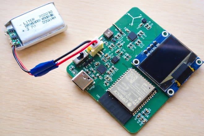
Once assembled, connect a 3.7V Lithium-Ion battery to the battery connector.
To program the ESP32 module, connect an Type-C USB Cable to the USB port. The board has a CP2104 chip for programming and establishing Serial Communication.
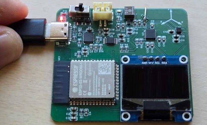
For charging, simply plug in a Type-C USB cable to the onboard USB connector. A red LED will light up to indicate USB power. You can use a multimeter and check if the battery is being charged or not, as there will be an increase in battery voltage during charging.
Source Code/Program for ESP32 Vehicle Motion Analyzer Board
Let us take a look at the main firmware of the ESP32 Vehicle Motion Analyzer. It initializes the MPU6050 accelerometer/gyroscope, LIS3MDL magnetometer, OLED display, Wi-Fi connection, and web server. The ESP32 reads motion data from the sensors, applies calibration and filtering, and calculates important vehicle parameters such as forward acceleration, lateral acceleration, yaw rate, and heading. The heading is obtained using the magnetometer with tilt compensation, while the accelerometer and gyroscope data are used to detect vehicle motion.
The program also identifies driving events such as harsh acceleration, harsh braking, and sharp left or right turnsbased on predefined thresholds. These results are shown in real time on the OLED display, where the user can see the heading, current motion event, acceleration values, yaw rate, and event counters. During startup, the code performs sensor calibration, loads saved magnetometer calibration values from memory, and briefly displays the Wi-Fi IP address on the OLED after connecting.
In addition, the code creates a web-based dashboard that can be accessed from a smartphone over Wi-Fi. Through this dashboard, users can monitor live motion data and control the CSV data logging feature. Logged data is stored in the ESP32’s internal LittleFS file system and can be started, stopped, cleared, or downloaded through the web interface.
The code requires following libraries. You can download and upload it to the Arduino Library Folder:
The code consists of two sections: one for the main.ino file and another for the webpage.h file. Both of these files need to be added to the same Arduino project folder so that the program can compile and run properly.
main.ino File
Here is the main.ino code for the ESP32 Vehicle Motion Analyzer project. From the following lines, change the WiFi SSID and password.
|
1 2 |
static const char* WIFI_SSID = "*************************"; static const char* WIFI_PASS = "*************************"; |
Copy the following code and paste it on your Arduino IDE editor Window.
|
1 2 3 4 5 6 7 8 9 10 11 12 13 14 15 16 17 18 19 20 21 22 23 24 25 26 27 28 29 30 31 32 33 34 35 36 37 38 39 40 41 42 43 44 45 46 47 48 49 50 51 52 53 54 55 56 57 58 59 60 61 62 63 64 65 66 67 68 69 70 71 72 73 74 75 76 77 78 79 80 81 82 83 84 85 86 87 88 89 90 91 92 93 94 95 96 97 98 99 100 101 102 103 104 105 106 107 108 109 110 111 112 113 114 115 116 117 118 119 120 121 122 123 124 125 126 127 128 129 130 131 132 133 134 135 136 137 138 139 140 141 142 143 144 145 146 147 148 149 150 151 152 153 154 155 156 157 158 159 160 161 162 163 164 165 166 167 168 169 170 171 172 173 174 175 176 177 178 179 180 181 182 183 184 185 186 187 188 189 190 191 192 193 194 195 196 197 198 199 200 201 202 203 204 205 206 207 208 209 210 211 212 213 214 215 216 217 218 219 220 221 222 223 224 225 226 227 228 229 230 231 232 233 234 235 236 237 238 239 240 241 242 243 244 245 246 247 248 249 250 251 252 253 254 255 256 257 258 259 260 261 262 263 264 265 266 267 268 269 270 271 272 273 274 275 276 277 278 279 280 281 282 283 284 285 286 287 288 289 290 291 292 293 294 295 296 297 298 299 300 301 302 303 304 305 306 307 308 309 310 311 312 313 314 315 316 317 318 319 320 321 322 323 324 325 326 327 328 329 330 331 332 333 334 335 336 337 338 339 340 341 342 343 344 345 346 347 348 349 350 351 352 353 354 355 356 357 358 359 360 361 362 363 364 365 366 367 368 369 370 371 372 373 374 375 376 377 378 379 380 381 382 383 384 385 386 387 388 389 390 391 392 393 394 395 396 397 398 399 400 401 402 403 404 405 406 407 408 409 410 411 412 413 414 415 416 417 418 419 420 421 422 423 424 425 426 427 428 429 430 431 432 433 434 435 436 437 438 439 440 441 442 443 444 445 446 447 448 449 450 451 452 453 454 455 456 457 458 459 460 461 462 463 464 465 466 467 468 469 470 471 472 473 474 475 476 477 478 479 480 481 482 483 484 485 486 487 488 489 490 491 492 493 494 495 496 497 498 499 500 501 502 503 504 505 506 507 508 509 510 511 512 513 514 515 516 517 518 519 520 521 522 523 524 525 526 527 528 529 530 531 532 533 534 535 536 537 538 539 540 541 542 543 544 545 546 547 548 549 550 551 552 553 554 555 556 557 558 559 560 561 562 563 564 565 566 567 568 569 570 571 572 573 574 575 576 577 578 579 580 581 582 583 584 |
#include <Wire.h> #include <Preferences.h> #include <WiFi.h> #include <WebServer.h> #include <LittleFS.h> #include <Adafruit_Sensor.h> #include <Adafruit_MPU6050.h> #include <Adafruit_LIS3MDL.h> #include <Adafruit_GFX.h> #include <Adafruit_SSD1306.h> #include "webpage.h" // ================= I2C / OLED ================= #define SDA_PIN 8 #define SCL_PIN 9 #define I2C_FREQ 400000 #define OLED_ADDR 0x3C #define SCREEN_WIDTH 128 #define SCREEN_HEIGHT 64 Adafruit_SSD1306 display(SCREEN_WIDTH, SCREEN_HEIGHT, &Wire, -1); // ================= Wi-Fi (Phone Hotspot) ================= static const char* WIFI_SSID = "*************************"; static const char* WIFI_PASS = "*************************"; // ================= Web Server ================= WebServer server(80); // ================= Sensors ================= #define LIS3MDL_ADDR 0x1E Adafruit_MPU6050 mpu; Adafruit_LIS3MDL lis3mdl; // ================= Magnetometer calibration (NVS) ================= Preferences prefs; float offX = 0, offY = 0, offZ = 0; float scaleX = 1, scaleY = 1, scaleZ = 1; // Your local declination (degrees). Optional for “true north”. float declinationDeg = 3.3833f; // ================= Detection tuning ================= // Units: m/s^2 for accel, deg/s for gyro static const float G = 9.80665f; float TH_ACCEL_MS2 = 2.2f; float TH_BRAKE_MS2 = 2.8f; float TH_YAWRATE_DPS = 25.0f; float TH_LAT_MS2 = 2.0f; uint32_t MIN_EVENT_GAP_MS = 1200; uint32_t EVENT_HOLD_MS = 450; float ALPHA_A = 0.18f; float ALPHA_W = 0.18f; // ================= Bias calibration ================= float axBias=0, ayBias=0, azBias=0; float gxBias=0, gyBias=0, gzBias=0; // ================= State ================= float fAx=0, fAy=0, fAz=0; float fGz=0; float fYawSin=0, fYawCos=1; float headingDeg=0; uint32_t lastSampleMs=0; uint32_t lastEventMs=0; enum EventType { EV_NONE, EV_ACCEL, EV_BRAKE, EV_TURN_L, EV_TURN_R }; EventType lastEvent = EV_NONE; uint32_t accelStart=0, brakeStart=0, turnStart=0; int brakeCount=0, accelCount=0, turnCount=0; // ============== Logging to LittleFS ============== static const char* LOG_PATH = "/drive_log.csv"; bool loggingEnabled = false; uint32_t lastLogMs = 0; const uint32_t LOG_PERIOD_MS = 100; // 10 Hz // Latest values for web UI float ui_aFwd=0, ui_aLeft=0, ui_yawRate=0, ui_heading=0; const char* ui_event = "NONE"; // ================= Helpers ================= static inline float rad2deg(float r){ return r * 57.2957795f; } static inline float deg2rad(float d){ return d * 0.01745329252f; } static inline float wrap360(float deg){ while (deg < 0) deg += 360.0f; while (deg >= 360.0f) deg -= 360.0f; return deg; } bool loadCal() { prefs.begin("lis3mdl", true); bool ok = prefs.isKey("offX") && prefs.isKey("sX"); if (ok) { offX = prefs.getFloat("offX", 0); offY = prefs.getFloat("offY", 0); offZ = prefs.getFloat("offZ", 0); scaleX = prefs.getFloat("sX", 1); scaleY = prefs.getFloat("sY", 1); scaleZ = prefs.getFloat("sZ", 1); } prefs.end(); return ok; } void quickMagCenterCal(uint32_t ms=12000) { float minX= 1e9, minY= 1e9, minZ= 1e9; float maxX=-1e9, maxY=-1e9, maxZ=-1e9; uint32_t t0=millis(); while (millis()-t0 < ms) { sensors_event_t m; lis3mdl.getEvent(&m); float x=m.magnetic.x, y=m.magnetic.y, z=m.magnetic.z; if (x<minX) minX=x; if (x>maxX) maxX=x; if (y<minY) minY=y; if (y>maxY) maxY=y; if (z<minZ) minZ=z; if (z>maxZ) maxZ=z; delay(15); } offX = (maxX+minX)*0.5f; offY = (maxY+minY)*0.5f; offZ = (maxZ+minZ)*0.5f; scaleX = scaleY = scaleZ = 1.0f; } const char* eventName(EventType e){ switch(e){ case EV_ACCEL: return "HARSH ACCELERATION"; case EV_BRAKE: return "HARSH BRAKE"; case EV_TURN_L:return "SHARP TURN LEFT"; case EV_TURN_R:return "SHARP TURN RIGHT"; default: return "NONE"; } } const char* cardinal(float deg){ deg = wrap360(deg); if (deg < 22.5 || deg >= 337.5) return "N"; if (deg < 67.5) return "NE"; if (deg < 112.5) return "E"; if (deg < 157.5) return "SE"; if (deg < 202.5) return "S"; if (deg < 247.5) return "SW"; if (deg < 292.5) return "W"; return "NW"; } // ================= Axis mapping ================= // Keep your final mapping here: void mapToCarFrame(const sensors_event_t& a, const sensors_event_t& g, float &aFwd, float &aLeft, float &aUp, float &wRoll, float &wPitch, float &wYaw) { aFwd = a.acceleration.x; aLeft = a.acceleration.y; aUp = a.acceleration.z; wRoll = rad2deg(g.gyro.x); wPitch = rad2deg(g.gyro.y); wYaw = rad2deg(g.gyro.z); } // ================= Bias calibration at boot ================= void calibrateMPU(uint16_t samples=500) { float axS=0, ayS=0, azS=0; float gxS=0, gyS=0, gzS=0; for (uint16_t i=0;i<samples;i++) { sensors_event_t a,g,t; mpu.getEvent(&a,&g,&t); float aF,aL,aU,wR,wP,wY; mapToCarFrame(a,g, aF,aL,aU, wR,wP,wY); axS += aF; ayS += aL; azS += aU; gxS += wR; gyS += wP; gzS += wY; delay(5); } axBias = axS/samples; ayBias = ayS/samples; azBias = (azS/samples) - G; gxBias = gxS/samples; gyBias = gyS/samples; gzBias = gzS/samples; } // ================= Heading (tilt-compensated-ish using accel) ================= float computeHeadingDeg(float ax, float ay, float az) { float roll = atan2f(ay, az); float pitch = atan2f(-ax, sqrtf(ay*ay + az*az)); sensors_event_t m; lis3mdl.getEvent(&m); float mx = (m.magnetic.x - offX) * scaleX; float my = (m.magnetic.y - offY) * scaleY; float mz = (m.magnetic.z - offZ) * scaleZ; float cr = cosf(roll), sr = sinf(roll); float cp = cosf(pitch), sp = sinf(pitch); float mx2 = mx * cp + mz * sp; float my2 = mx * sr * sp + my * cr - mz * sr * cp; float hdg = rad2deg(atan2f(my2, mx2)); hdg = wrap360(hdg + declinationDeg); return hdg; } // ================= Detection logic ================= bool canCountEvent(uint32_t now){ return (now - lastEventMs) >= MIN_EVENT_GAP_MS; } void setEvent(EventType e, uint32_t now){ lastEvent = e; lastEventMs = now; if (e == EV_BRAKE) brakeCount++; else if (e == EV_ACCEL) accelCount++; else if (e == EV_TURN_L || e == EV_TURN_R) turnCount++; } // ================= OLED UI ================= void drawUI(float aFwd, float aLeft, float yawRateDps, float hdg) { display.clearDisplay(); display.setTextSize(1); display.setTextColor(SSD1306_WHITE); display.setCursor(0,0); display.print("HEADING: "); display.print(hdg, 0); display.print(" "); display.print(cardinal(hdg)); display.setCursor(0,10); display.print(eventName(lastEvent)); display.setCursor(0,20); display.print("Fwd a: "); display.print(aFwd, 1); display.print("m/s2 "); display.print(aFwd/G, 1); display.print("g"); display.setCursor(0,30); display.print("Lat a:"); display.print(aLeft, 1); display.print("m/s2 "); display.print(aLeft/G, 1); display.print("g"); display.setCursor(0,40); display.print("Yaw w:"); display.print(yawRateDps, 1); display.print("dps"); display.setCursor(0,50); display.print("B:"); display.print(brakeCount); display.print(" A:"); display.print(accelCount); display.print(" T:"); display.print(turnCount); display.display(); } // ================= LittleFS logging ================= void logHeaderIfNeeded() { if (!LittleFS.exists(LOG_PATH)) { File f = LittleFS.open(LOG_PATH, "w"); if (f) { f.println("ms,heading_deg,aFwd_ms2,aLeft_ms2,yawRate_dps,brakeCount,accelCount,turnCount,event"); f.close(); } } } void logLine(uint32_t msNow, float hdg, float aF, float aL, float wYaw) { File f = LittleFS.open(LOG_PATH, "a"); if (!f) return; f.printf("%lu,%.1f,%.3f,%.3f,%.2f,%d,%d,%d,%s\n", (unsigned long)msNow, hdg, aF, aL, wYaw, brakeCount, accelCount, turnCount, eventName(lastEvent)); f.close(); } // ================= Web handlers ================= void handleRoot() { server.send_P(200, "text/html", WEBPAGE_HTML); } void handleData() { // JSON for webpage polling String json = "{"; json += "\"ms\":" + String(millis()) + ","; json += "\"hdg\":" + String(ui_heading, 1) + ","; json += "\"card\":\"" + String(cardinal(ui_heading)) + "\","; json += "\"aF\":" + String(ui_aFwd, 3) + ","; json += "\"aL\":" + String(ui_aLeft, 3) + ","; json += "\"wYaw\":" + String(ui_yawRate, 2) + ","; json += "\"cB\":" + String(brakeCount) + ","; json += "\"cA\":" + String(accelCount) + ","; json += "\"cT\":" + String(turnCount) + ","; json += "\"event\":\"" + String(ui_event) + "\","; json += "\"logging\":" + String(loggingEnabled ? "true" : "false"); json += "}"; server.send(200, "application/json", json); } void handleStart() { loggingEnabled = true; logHeaderIfNeeded(); server.send(200, "text/plain", "Logging started"); } void handleStop() { loggingEnabled = false; server.send(200, "text/plain", "Logging stopped"); } void handleClear() { loggingEnabled = false; if (LittleFS.exists(LOG_PATH)) LittleFS.remove(LOG_PATH); server.send(200, "text/plain", "CSV cleared"); } void handleDownload() { if (!LittleFS.exists(LOG_PATH)) { server.send(404, "text/plain", "No log file yet. Press Start Logging first."); return; } File f = LittleFS.open(LOG_PATH, "r"); if (!f) { server.send(500, "text/plain", "Failed to open log file"); return; } server.streamFile(f, "text/csv"); f.close(); } // ================= Wi-Fi setup ================= void wifiConnect() { WiFi.mode(WIFI_STA); WiFi.begin(WIFI_SSID, WIFI_PASS); // Show connecting screen display.clearDisplay(); display.setTextSize(1); display.setTextColor(SSD1306_WHITE); display.setCursor(0,0); display.println("Connecting WiFi..."); display.print("SSID: "); display.println(WIFI_SSID); display.display(); uint32_t start = millis(); while (WiFi.status() != WL_CONNECTED && millis() - start < 20000) { delay(300); } display.clearDisplay(); display.setCursor(0,0); if (WiFi.status() == WL_CONNECTED) { IPAddress ip = WiFi.localIP(); // ✅ Show IP for 5 seconds display.println("WiFi Connected"); display.print("IP: "); display.println(ip); display.println(); display.println("Open in phone:"); display.print("http://"); display.println(ip); display.display(); Serial.print("ESP32 IP: "); Serial.println(ip); delay(5000); // ✅ hold IP screen for 5 seconds // Optional: clear after the 5s so your normal UI draws next display.clearDisplay(); display.display(); } else { display.println("WiFi FAILED"); display.println("Check hotspot"); display.println("SSID / PASS"); display.display(); Serial.println("WiFi connect failed"); // Optional: keep this message visible a bit delay(3000); } } // ================= Setup/Loop ================= void setup() { Serial.begin(115200); delay(200); Wire.begin(SDA_PIN, SCL_PIN); Wire.setClock(I2C_FREQ); if (!display.begin(SSD1306_SWITCHCAPVCC, OLED_ADDR)) { while (1) delay(10); } display.clearDisplay(); display.setTextSize(1); display.setTextColor(SSD1306_WHITE); display.setCursor(0,0); display.println("Driving Analyzer"); display.println("Init sensors..."); display.display(); if (!mpu.begin()) { display.println("MPU6050 FAIL"); display.display(); while (1) delay(10); } mpu.setAccelerometerRange(MPU6050_RANGE_8_G); mpu.setGyroRange(MPU6050_RANGE_500_DEG); mpu.setFilterBandwidth(MPU6050_BAND_10_HZ); if (!lis3mdl.begin_I2C(LIS3MDL_ADDR, &Wire)) { display.println("MAG FAIL"); display.display(); while (1) delay(10); } lis3mdl.setOperationMode(LIS3MDL_CONTINUOUSMODE); lis3mdl.setDataRate(LIS3MDL_DATARATE_155_HZ); lis3mdl.setRange(LIS3MDL_RANGE_4_GAUSS); if (!loadCal()) { display.clearDisplay(); display.setCursor(0,0); display.println("Mag quick cal"); display.println("Rotate 12 sec"); display.display(); quickMagCenterCal(12000); } display.clearDisplay(); display.setCursor(0,0); display.println("Calibrating IMU..."); display.println("Keep still!"); display.display(); calibrateMPU(500); // Filesystem for logging if (!LittleFS.begin(true)) { Serial.println("LittleFS mount failed!"); } // Wi-Fi + Web server wifiConnect(); server.on("/", handleRoot); server.on("/data", handleData); server.on("/start", handleStart); server.on("/stop", handleStop); server.on("/clear", handleClear); server.on("/download", handleDownload); server.begin(); Serial.println("Web server started."); lastSampleMs = millis(); lastEventMs = millis(); lastEvent = EV_NONE; fYawSin = 0; fYawCos = 1; } void loop() { server.handleClient(); uint32_t now = millis(); if (now - lastSampleMs < 20) return; // ~50 Hz lastSampleMs = now; sensors_event_t a, g, t; mpu.getEvent(&a, &g, &t); float aF,aL,aU,wR,wP,wY; mapToCarFrame(a,g, aF,aL,aU, wR,wP,wY); // Remove biases aF -= axBias; aL -= ayBias; aU -= azBias; wR -= gxBias; wP -= gyBias; wY -= gzBias; // Smooth fAx += ALPHA_A * (aF - fAx); fAy += ALPHA_A * (aL - fAy); fAz += ALPHA_A * (aU - fAz); fGz += ALPHA_W * (wY - fGz); // Heading float hdg = computeHeadingDeg(fAx, fAy, fAz); // Circular smoothing for heading display float hr = deg2rad(hdg); fYawSin += 0.12f * (sinf(hr) - fYawSin); fYawCos += 0.12f * (cosf(hr) - fYawCos); headingDeg = rad2deg(atan2f(fYawSin, fYawCos)); if (headingDeg < 0) headingDeg += 360.0f; // Event detection if (fAx > TH_ACCEL_MS2) { if (accelStart == 0) accelStart = now; if ((now - accelStart) > EVENT_HOLD_MS && canCountEvent(now)) { setEvent(EV_ACCEL, now); accelStart = 0; } } else accelStart = 0; if (fAx < -TH_BRAKE_MS2) { if (brakeStart == 0) brakeStart = now; if ((now - brakeStart) > EVENT_HOLD_MS && canCountEvent(now)) { setEvent(EV_BRAKE, now); brakeStart = 0; } } else brakeStart = 0; float yawRate = fGz; bool turning = (fabsf(yawRate) > TH_YAWRATE_DPS) || (fabsf(fAy) > TH_LAT_MS2); if (turning) { if (turnStart == 0) turnStart = now; if ((now - turnStart) > EVENT_HOLD_MS && canCountEvent(now)) { setEvent((yawRate >= 0) ? EV_TURN_L : EV_TURN_R, now); turnStart = 0; } } else turnStart = 0; // OLED drawUI(fAx, fAy, yawRate, headingDeg); // Update UI values for web endpoint ui_aFwd = fAx; ui_aLeft = fAy; ui_yawRate = yawRate; ui_heading = headingDeg; ui_event = eventName(lastEvent); // Logging (10 Hz) if (loggingEnabled && (now - lastLogMs >= LOG_PERIOD_MS)) { lastLogMs = now; logHeaderIfNeeded(); logLine(now, headingDeg, fAx, fAy, yawRate); } // Serial debug (optional) static uint32_t lastPrint=0; if (now - lastPrint > 500) { lastPrint = now; Serial.printf("IP=%s | aF=%.2f aL=%.2f wYaw=%.1f hdg=%.0f | B:%d A:%d T:%d | %s | log=%d\n", (WiFi.status()==WL_CONNECTED)?WiFi.localIP().toString().c_str():"NA", fAx, fAy, yawRate, headingDeg, brakeCount, accelCount, turnCount, eventName(lastEvent), loggingEnabled ? 1 : 0); } } |
webpage.h File
Here is the webpage file for webserver, which combines html, CSS, JavaScript and other files. Create a webpage.h file in the same Arduino editor window and paste the following code there.
|
1 2 3 4 5 6 7 8 9 10 11 12 13 14 15 16 17 18 19 20 21 22 23 24 25 26 27 28 29 30 31 32 33 34 35 36 37 38 39 40 41 42 43 44 45 46 47 48 49 50 51 52 53 54 55 56 57 58 59 60 61 62 63 64 65 66 67 68 69 70 71 72 73 74 75 76 77 78 79 80 81 82 83 84 85 86 87 88 89 90 91 92 93 94 95 96 97 98 99 100 101 102 103 104 105 106 107 108 109 110 111 112 113 114 115 116 117 118 119 120 121 122 123 124 125 126 127 128 129 130 131 132 133 134 135 136 137 138 139 140 141 142 143 144 145 146 147 148 149 150 151 152 153 154 155 156 157 158 159 160 161 162 163 164 165 166 167 168 169 170 171 172 173 174 175 176 177 178 179 180 181 182 183 184 185 186 187 188 189 190 191 192 193 194 195 196 197 198 199 200 201 202 203 204 205 206 207 208 209 210 211 212 213 214 215 216 217 218 219 220 221 222 223 224 225 226 227 228 229 230 231 232 233 234 235 236 237 238 239 240 241 242 243 244 245 246 247 248 249 250 251 252 253 254 255 256 257 258 259 260 261 262 263 264 265 266 267 268 269 270 271 272 273 274 275 276 277 278 279 280 281 282 283 284 285 286 287 288 289 290 291 292 293 294 295 296 297 298 299 300 301 302 303 304 305 306 307 308 309 310 311 312 313 314 315 316 317 318 319 320 321 322 323 324 325 326 327 328 329 330 331 332 333 334 335 336 337 338 339 340 341 342 343 344 345 346 347 348 349 350 351 352 353 354 355 356 357 358 359 360 361 362 363 364 365 366 367 368 369 370 371 372 373 374 375 376 377 378 379 380 381 382 383 |
#pragma once #include <pgmspace.h> static const char WEBPAGE_HTML[] PROGMEM = R"HTML( <!doctype html> <html lang="en"> <head> <meta charset="utf-8" /> <meta name="viewport" content="width=device-width,initial-scale=1,viewport-fit=cover" /> <title>Driving Analyzer</title> <style> :root{ --bg:#f7f8fb; --card:#ffffff; --text:#0f172a; --muted:#64748b; --line:rgba(15,23,42,.10); --shadow: 0 10px 30px rgba(2,6,23,.08); --r:16px; --good:#16a34a; --warn:#f59e0b; --bad:#dc2626; --blue:#2563eb; --chip:#f1f5f9; } *{ box-sizing:border-box; } html,body{ height:100%; } body{ margin:0; font-family: ui-sans-serif, system-ui, -apple-system, Segoe UI, Roboto, Arial; background: radial-gradient(1200px 900px at 10% -20%, rgba(37,99,235,.10), transparent 60%), radial-gradient(1000px 700px at 100% 0%, rgba(22,163,74,.09), transparent 55%), var(--bg); color:var(--text); -webkit-font-smoothing:antialiased; padding: 14px 14px 132px; /* extra for sticky logging heading + buttons */ } .topbar{ display:flex; align-items:center; justify-content:space-between; gap:12px; margin-bottom:12px; } .title{ display:flex; flex-direction:column; line-height:1.1; } .title h1{ margin:0; font-size:18px; font-weight:900; letter-spacing:.2px; } .title .sub{ margin-top:4px; font-size:12px; color:var(--muted); } .pill{ display:flex; align-items:center; gap:8px; padding:8px 10px; border:1px solid var(--line); border-radius:999px; background: rgba(255,255,255,.70); box-shadow: var(--shadow); font-size:12px; color:var(--muted); white-space:nowrap; } .dot{ width:10px;height:10px;border-radius:999px; background: var(--warn); box-shadow: 0 0 0 4px rgba(245,158,11,.18); } .dot.ok{ background: var(--good); box-shadow: 0 0 0 4px rgba(22,163,74,.16); } .dot.bad{ background: var(--bad); box-shadow: 0 0 0 4px rgba(220,38,38,.14); } .grid{ display:grid; grid-template-columns: 1fr 1fr; gap:12px; } .wide{ grid-column: 1 / -1; } .card{ background: var(--card); border:1px solid var(--line); border-radius: var(--r); padding:12px; box-shadow: var(--shadow); overflow:hidden; } .k{ font-size:11px; color:var(--muted); letter-spacing:.2px; } .v{ margin-top:6px; font-size:26px; font-weight:900; } .unit{ font-size:12px; color:var(--muted); font-weight:700; margin-left:6px; } .mini{ margin-top:6px; font-size:12px; color:var(--muted); } .row{ display:flex; align-items:center; justify-content:space-between; gap:10px; } .badge{ padding:6px 10px; border-radius:999px; border:1px solid var(--line); background: rgba(2,6,23,.03); font-size:12px; color: var(--muted); white-space:nowrap; font-weight:900; } .badge.good{ background:rgba(22,163,74,.08); color:var(--good); border-color: rgba(22,163,74,.25); } .chips{ display:flex; gap:8px; flex-wrap:wrap; margin-top:10px; } .chip{ flex:1 1 auto; min-width: 96px; padding:10px 10px; border-radius: 14px; background: var(--chip); border: 1px solid rgba(15,23,42,.08); display:flex; align-items:center; justify-content:space-between; } .chip b{ font-size:18px; font-weight:900; } .chip span{ font-size:12px; color:var(--muted); font-weight:900; } .meter{ margin-top:10px; height:10px; border-radius: 999px; background: rgba(2,6,23,.06); border:1px solid rgba(15,23,42,.10); overflow:hidden; } .fill{ height:100%; width:0%; background: linear-gradient(90deg, rgba(22,163,74,.95), rgba(245,158,11,.95), rgba(220,38,38,.95)); border-radius:999px; transition: width .2s ease; } .footer{ margin-top:12px; color: var(--muted); font-size:12px; line-height:1.4; } a{ color: var(--blue); text-decoration:none; font-weight:900; } /* Sticky controls (mobile) */ .controls{ position:fixed; left:0; right:0; bottom:0; padding: 10px 12px calc(10px + env(safe-area-inset-bottom)); background: rgba(247,248,251,.92); backdrop-filter: blur(10px); border-top:1px solid rgba(15,23,42,.10); } .log-title{ font-size:12px; font-weight:900; letter-spacing:.35px; color:#334155; margin: 0 2px 8px; } .btnrow{ display:flex; gap:10px; justify-content:space-between; } .btn{ flex:1 1 auto; border-radius: 14px; padding: 12px 12px; border: 1px solid rgba(15,23,42,.12); background: #fff; color: var(--text); font-weight: 900; font-size: 14px; box-shadow: 0 8px 20px rgba(2,6,23,.06); } .btn.primary{ background: rgba(37,99,235,.10); border-color: rgba(37,99,235,.25); color: #1e40af; } .btn.stop{ background: rgba(245,158,11,.10); border-color: rgba(245,158,11,.25); color:#92400e; } .btn.danger{ background: rgba(220,38,38,.10); border-color: rgba(220,38,38,.22); color:#7f1d1d; } .btn:active{ transform: translateY(1px); } @media (max-width: 360px){ .v{ font-size:22px; } .chip{ min-width: 80px; } } </style> </head> <body> <div class="topbar"> <div class="title"> <h1>Driving Analyzer</h1> <div class="sub">Live dashboard + CSV logger</div> </div> <div class="pill"> <span class="dot" id="dot"></span> <span id="conn">connecting…</span> </div> </div> <div class="grid"> <div class="card wide"> <div class="row"> <div> <div class="k">CURRENT EVENT</div> <div class="v" id="event">--</div> </div> <div class="badge" id="logBadge">LOG OFF</div> </div> <div class="chips"> <div class="chip"><span>Brake</span> <b id="cB">0</b></div> <div class="chip"><span>Acceleration</span> <b id="cA">0</b></div> <div class="chip"><span>Turn</span> <b id="cT">0</b></div> </div> </div> <div class="card"> <div class="k">HEADING</div> <div class="v"><span id="hdg">--</span><span class="unit">°</span></div> <div class="mini"><span id="card">--</span> • <span id="ms">--</span> ms</div> </div> <div class="card"> <div class="k">YAW RATE</div> <div class="v"><span id="wYaw">--</span><span class="unit">°/s</span></div> <div class="mini">Turn intensity</div> <div class="meter"><div class="fill" id="yawFill"></div></div> </div> <div class="card"> <div class="k">FORWARD ACCELERATION</div> <div class="v"><span id="aF">--</span><span class="unit">m/s²</span></div> <div class="mini"><span id="aFg">--</span> g</div> <div class="meter"><div class="fill" id="fwdFill"></div></div> </div> <div class="card"> <div class="k">LATERAL ACCELERATION</div> <div class="v"><span id="aL">--</span><span class="unit">m/s²</span></div> <div class="mini"><span id="aLg">--</span> g</div> <div class="meter"><div class="fill" id="latFill"></div></div> </div> <div class="footer wide"> Data: <a href="/data" target="_blank">/data</a> • Download: <a href="/download">/download</a> • Tip: “Add to Home Screen” for an app-like view. </div> </div> <div class="controls"> <div class="log-title">DATA LOGGING</div> <div class="btnrow"> <button class="btn primary" onclick="cmd('/start')">Start</button> <button class="btn stop" onclick="cmd('/stop')">Stop</button> <button class="btn" onclick="window.location='/download'">CSV</button> <button class="btn danger" onclick="cmd('/clear')">Clear</button> </div> </div> <script> const G = 9.80665; let lastOk = 0; function clamp01(x){ return Math.max(0, Math.min(1, x)); } function setFill(id, value, maxAbs){ const pct = clamp01(Math.abs(value) / maxAbs) * 100; document.getElementById(id).style.width = pct.toFixed(0) + '%'; } function connState(state){ const dot = document.getElementById('dot'); const txt = document.getElementById('conn'); if(state === 'ok'){ dot.className = 'dot ok'; txt.textContent = 'live'; }else if(state === 'bad'){ dot.className = 'dot bad'; txt.textContent = 'offline'; }else{ dot.className = 'dot'; txt.textContent = 'connecting…'; } } function logBadge(on){ const el = document.getElementById('logBadge'); el.textContent = on ? 'LOG ON' : 'LOG OFF'; el.className = 'badge ' + (on ? 'good' : ''); } async function cmd(path){ try{ const r = await fetch(path, {cache:'no-store'}); const t = await r.text(); document.querySelector('.sub').textContent = t; setTimeout(()=>{ document.querySelector('.sub').textContent = 'Live dashboard + CSV logger'; }, 1400); }catch(e){ document.querySelector('.sub').textContent = 'Error: ' + e; connState('bad'); } } async function poll(){ try{ const r = await fetch('/data', {cache:'no-store'}); const j = await r.json(); document.getElementById('hdg').textContent = (j.hdg ?? 0).toFixed(0); document.getElementById('card').textContent = j.card ?? '--'; document.getElementById('ms').textContent = j.ms ?? 0; document.getElementById('aF').textContent = (j.aF ?? 0).toFixed(2); document.getElementById('aL').textContent = (j.aL ?? 0).toFixed(2); document.getElementById('aFg').textContent = ((j.aF ?? 0)/G).toFixed(2); document.getElementById('aLg').textContent = ((j.aL ?? 0)/G).toFixed(2); document.getElementById('wYaw').textContent = (j.wYaw ?? 0).toFixed(1); document.getElementById('cB').textContent = j.cB ?? 0; document.getElementById('cA').textContent = j.cA ?? 0; document.getElementById('cT').textContent = j.cT ?? 0; document.getElementById('event').textContent = j.event ?? 'NONE'; logBadge(!!j.logging); // Meters (same as before) setFill('yawFill', (j.wYaw ?? 0), 60); setFill('fwdFill', (j.aF ?? 0), 5.0); setFill('latFill', (j.aL ?? 0), 5.0); lastOk = Date.now(); connState('ok'); }catch(e){ if(Date.now() - lastOk > 2000) connState('bad'); } } setInterval(poll, 200); // 5 Hz poll(); </script> </body> </html> )HTML"; |
Testing the ESP32 Vehicle Motion Analyzer
Open the Arduino IDE and go to the Board Manager. Select the ESP32-S3 Development Board and choose the correct COM port connected to your device. After selecting the board and port, upload the program to the ESP32.
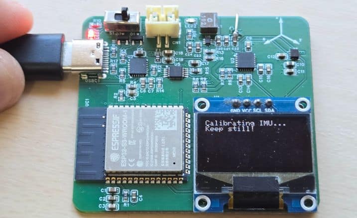
Once the code is uploaded, the OLED display initializes and the sensors begin calibration. During this process, the screen shows initialization messages. After the calibration is completed, the device connects to the configured Wi-Fi network and the IP address of the ESP32 is displayed on the OLED for a few seconds.
After initialization, the OLED starts showing real-time motion data, including vehicle heading, forward acceleration, lateral acceleration, yaw rate, and detected events such as harsh acceleration, harsh braking, or sharp turns. All the results are based on MUP6050 Accelerometer, Gyroscope and LIS3MDL Magnetometer with ESP32 data processing.
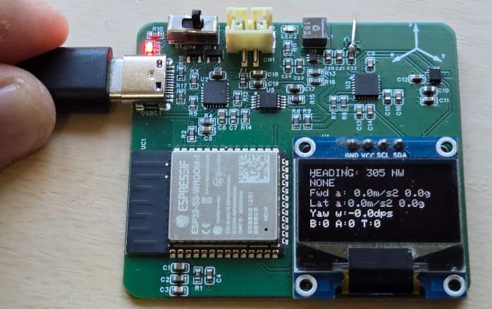
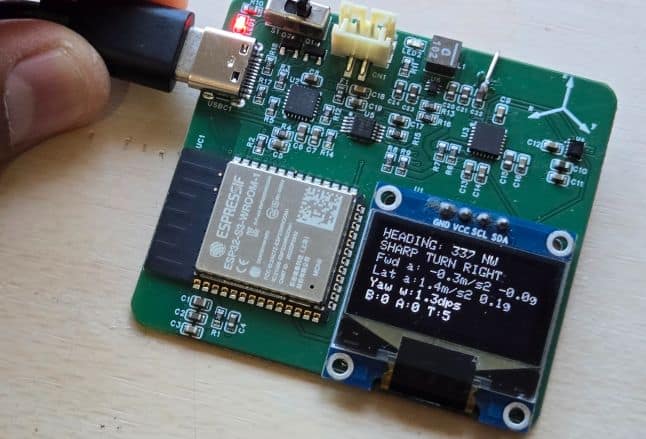
To test the system, gently rotate or tilt the device in different directions. You should observe changes in heading, acceleration values, and yaw rate on the OLED display. Rapid movements will trigger events such as sharp turns or harsh acceleration, which will also be indicated on the screen.
For web monitoring, connect your phone to the same Wi-Fi network and open the IP address shown on the OLED in a web browser.
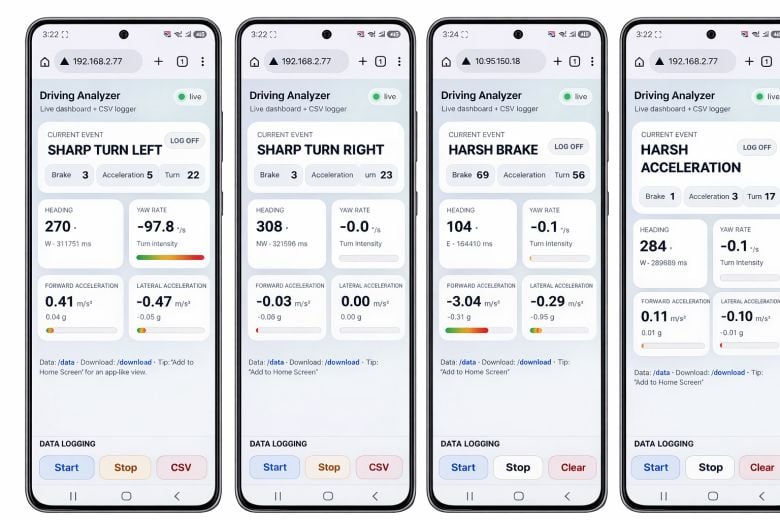
This will open the web dashboard, where you can view live motion data and start, stop, clear, or download the CSV data logs for further analysis.
For testing, I kept the device of my car dashboard and went outside for real life testing.
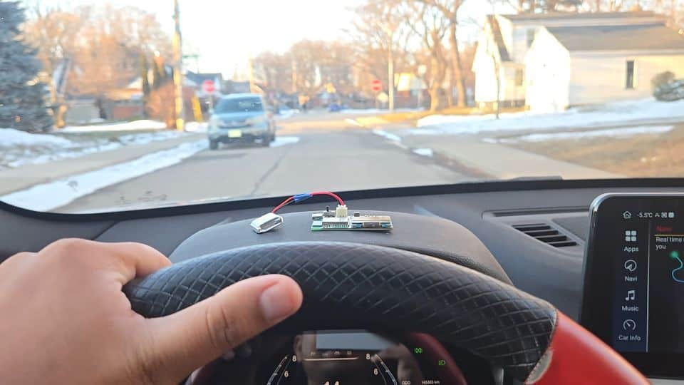
The result were very good and it was successfully able to detect acceleration, harsh break, left-right turns etc.\
Video Tutorial & Guide


