

Overview
In this article, we will be interfacing the BNO08x IMU with ESP32 to measure Pitch, Roll, and Yaw with very high accuracy and virtually no drift. The BNO08x family, which includes BNO080, BNO085, and BNO086, integrates an accelerometer, gyroscope, and magnetometer into a single sensor and uses advanced sensor fusion algorithms to provide stable orientation data, including drift-free yaw. You can build an IoT Activity Tracker project using BNO080.
Earlier, we implemented sensor fusion using the MPU6050 accelerometer-gyroscope and the HMC5883L magnetometer with ESP32 to measure Pitch, Roll, and Yaw. You can refer to the MPU6050 & HMC5883L Sensor Fusion article for that approach. However, the implementation required complex code and multiple algorithms, and the results were still not very accurate. Issues such as drift and noise were present even after careful tuning.
Another limitation was the hardware itself. The MPU6050, released around 2010, shows higher noise levels compared to modern IMUs. Additionally, the HMC5883L magnetometer is now obsolete, and the manufacturer has discontinued its production, making it unsuitable for new designs.
So the proper replacement for MPU6050 & HMC5883L is BNO08x. In this tutorial, we will implement the BNO08x complete setup using Arduino C++ code on the ESP32 and interface an OLED display to visualize real-time Pitch, Roll, and Yaw values. The displayed data is tested under static and dynamic conditions to verify measurement accuracy, stability, and yaw drift performance.
Bill of Materials
Following is the list of components that is required for this project.
| S.N. | Components Name | Quantity | Purchase Link |
|---|---|---|---|
| 1 | ESP32 Board | 1 | Amazon | AliExpress |
| 2 | BNO08x Accelerometer Gyroscope Magnetometer | 1 | Amazon | AliExpress |
| 3 | OLED Display | Amazon | AliExpress | |
| 4 | Connecting Wires | 10 | Amazon | AliExpress |
| 5 | Breadboard | 2 | Amazon | AliExpress |
BNO08X Accelerometer Gyroscope Magnetometer
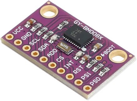
The BNO08x is a high-performance 9-axis absolute orientation sensor module that integrates a triaxial accelerometer, gyroscope, magnetometer, and an onboard 32-bit ARM® Cortex-M0+ microcontroller in a compact System-in-Package (SiP). It is designed to function as a complete sensor hub, providing accurate motion, orientation, and heading information without requiring complex processing from the host microcontroller.
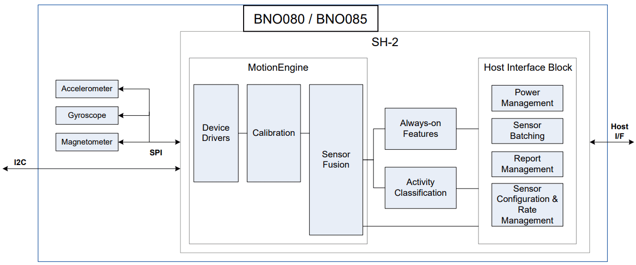
The module runs CEVA-Hillcrest’s SH-2 MotionEngine™ firmware, which performs real-time sensor fusion, dynamic calibration, and motion processing internally. By combining raw sensor data into stable outputs such as rotation vectors, quaternions, and linear acceleration, the BNO08x eliminates drift and reduces development effort while improving system reliability.
With support for multiple communication interfaces, including I²C, SPI, and UART, the BNO08x is well suited for applications such as robotics, wearable devices, AR/VR systems, and IoT platforms where low latency, low power consumption, and high-accuracy motion sensing are critical.
- Check BNO08x Datasheet: BNO08x Datasheet
Core Features
- 9-axis motion sensing: 3-axis accelerometer, gyroscope, and magnetometer
- Integrated ARM® Cortex-M0+ MCU running SH-2 MotionEngine™ firmware
- On-chip real-time sensor fusion with absolute orientation and heading output
- Dynamic, continuous self-calibration for temperature variation and sensor aging
- “Always-on” motion and activity detection:
- Step counter
- Tap detector
- Stability and motion classification
- Offloads motion processing from host MCU, reducing system power and CPU load
- Android-compatible sensor hub architecture
- Supports firmware upgrades via device firmware update (DFU)
Technical Specifications
Motion Sensors
- Accelerometer: ±8 g range, 12-bit resolution
- Gyroscope: ±2000 °/s range, 16-bit resolution
- Magnetometer: 3-axis geomagnetic sensor
Motion Outputs
- Orientation: Quaternion, Euler angles, rotation vectors
- Linear acceleration and gravity vectors
- Gyro rotation vector output up to 1 kHz (optimized for AR/VR)
Electrical Characteristics
- Supply voltage (VDD): 2.4 V – 3.6 V
- I/O voltage (VDDIO): 1.65 V – 3.6 V
- Typical current consumption:
- Low-power / always-on modes: tens of µA
- Full sensor fusion operation: a few mA (mode and data rate dependent
Interfaces
- I²C (up to 400 kHz)
- SPI
- UART (SHTP and UART-RVC modes)
Sensor Fusion Algorithm
The BNO08x uses CEVA-Hillcrest MotionEngine™, a real-time sensor fusion algorithm that combines accelerometer, gyroscope, and magnetometer data to generate accurate, stable, and drift-corrected motion outputs. The algorithm continuously processes raw sensor data to compute absolute orientation, angular motion, and gravity-compensated linear acceleration.
MotionEngine™ performs automatic background calibration to compensate for sensor bias, temperature changes, and long-term drift. Gyroscope drift is corrected using accelerometer and magnetometer references, while magnetic distortion detection ensures reliable heading estimation in non-ideal environments.
Multiple fusion modes are supported, including Game, Geomagnetic, and AR/VR-stabilized rotation vectors, allowing optimization for either low latency or absolute accuracy. This approach provides the host MCU with ready-to-use motion data, reducing processing load and system complexity.
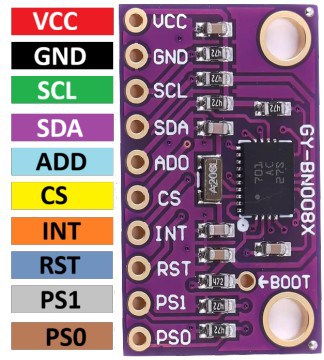
Pinout of BNO08x
The GY-BNO08x breakout board exposes ten essential pins required for power,
communication, interrupts, reset, and interface selection. These pins allow
the BNO08x to operate in I²C or SPI mode with minimal external
components.
| Pin No. | Pin Name | Function |
|---|---|---|
| 1 | VCC | Power supply input (typically 3.3 V). Supplies both the sensor core and the I/O |
| 2 | GND | Ground reference |
| 3 | SCL | I²C clock line (H_SCL) |
| 4 | SDA | I²C data line (H_SDA) |
| 5 | ADO | I²C address select (SA0). LOW = 0x4A, HIGH = 0x4B |
| 6 | CS | SPI chip select (active low). Must be pulled HIGH when using I²C |
| 7 | INT | Interrupt output (H_INTN), active low. Signals data ready or events |
| 8 | RST | Active-low hardware reset (NRST) |
| 9 | PS1 | Interface selection pin (Protocol Select 1) |
| 10 | PS0 | Interface selection pin (Protocol Select 0 / SPI wake) |
BNO08x Connectivity (Communication Protocol
The BNO08X can support connections to a host microcontroller through various serial interfaces:
- I²C interface
- UART interface
- SPI interface
- UART-RVC interface – a simplified UART interface for unmanned ground roving robots (such as robot vacuum cleaners)
In addition, the BNO08X includes a bootloader to allow for firmware upgrades. The bootloader can support
I²C, SPI, or UART. Access to the bootloader is achieved by setting BOOTN to 0.
Configuration of the communication interface is achieved by setting the protocol selection (PS1/PS0)
pins appropriately.
Protocol Selection for BNO08X
| PS1 | PS0 | BNO08X (BOOTN = 1) | BNO08X Bootloader (BOOTN = 0) |
|---|---|---|---|
| 0 | 0 | I²C | I²C |
| 0 | 1 | UART-RVC | Reserved |
| 1 | 0 | UART | UART |
| 1 | 1 | SPI | SPI |
The protocol selection and BOOTN pins are sampled at reset.
PS0 is repurposed as a WAKE signal in SPI mode following reset.
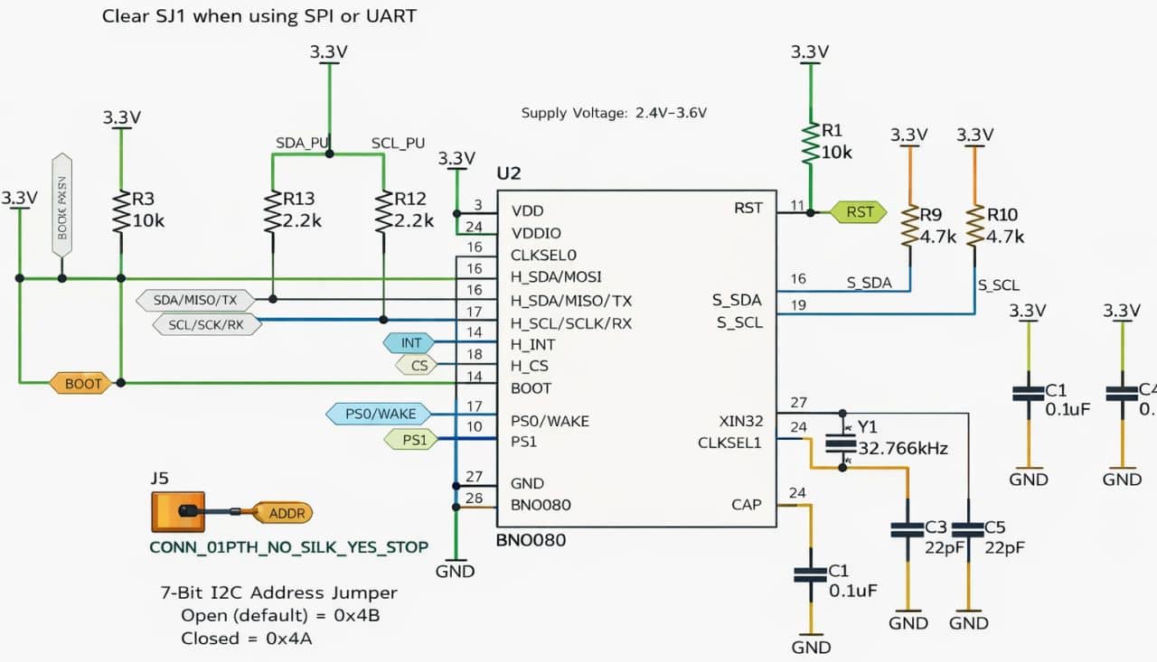
BNO08x Module Schematic
Here is the typical application circuit for the BNO080 IMU, configured primarily for I²C communication with selectable address and interface control.
Differences Between BNO080, BNO085, and BNO086
| Aspect | BNO080 | BNO085 | BNO086 |
|---|---|---|---|
| Sensor Fusion Firmware | Standard SH-2 MotionEngine™ | Enhanced MotionEngine™ | Enhanced MotionEngine™ |
| AR/VR Optimization | No | Yes | Yes |
| Orientation Prediction | Basic | Improved prediction | Improved prediction |
| Gyro Rotation Vector Latency | Standard | Lower latency | Lower latency |
| Host-Based AR/VR Support | Not supported | Supported | Supported |
| Intended Use | General motion sensing | AR/VR controllers & headsets | AR/VR controllers & headsets |
| Firmware Feature Set | Baseline | Extended | Extended / latest |
Comparision Between MPU6050, BMI160, and BNO08x
| Aspect | MPU6050 | BMI160 | BNO08x (BNO080/85/86) |
|---|---|---|---|
| Sensor Type | 6-axis IMU | 6-axis IMU | 9-axis Sensor Hub |
| Sensors Included | Accelerometer + Gyroscope | Accelerometer + Gyroscope | Accelerometer + Gyroscope + Magnetometer |
| On-Chip MCU | ❌ No | ❌ No | ✅ Yes (ARM Cortex-M0+) |
| Sensor Fusion | ❌ Not onboard | ❌ Not onboard | ✅ On-chip MotionEngine™ |
| Orientation Output | Raw data only | Raw data only | Absolute orientation, quaternions, rotation vectors |
| Drift Compensation | Host-side only | Host-side only | Automatic, real-time |
| Calibration | Manual (host) | Manual (host) | Automatic background calibration |
| AR/VR Support | ❌ No | ❌ No | ✅ Optimized (BNO085/086) |
| Host Processing Load | High | Medium | Very low |
| Power Consumption | Moderate | Low | Low (mode dependent) |
| Communication | I²C | I²C, SPI | I²C, SPI, UART |
| Typical Use Case | Basic motion sensing | Wearables, low-power IMU | Robotics, AR/VR, navigation |
| Complexity to Use | Low | Medium | Very low (high-level data) |
Interfacing BNO08x with ESP32 Microcontroller & OLED Display
Now let us interface the BNO08x IMU – BNO080, BNO085, and BNO086 – with the ESP32 microcontroller. This setup demonstrates how to connect the sensor and communicate with it to obtain accurate motion and orientation data.
The motion data can be displayed on 0.96″ I2C OLED Display.
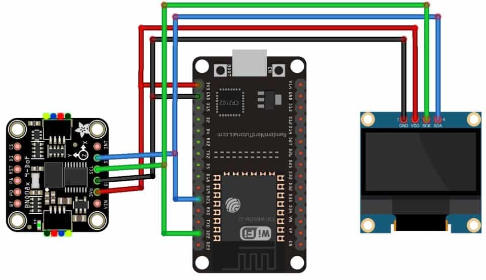
The BNO08x IMU and OLED display are connected to the ESP32 via the I²C bus. Both devices share SDA (GPIO 21) and SCL (GPIO 22) lines, with VCC connected to 3.3 V and GND to common ground.
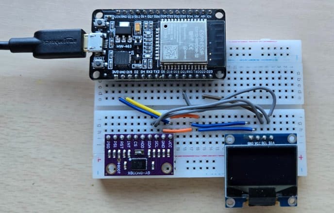
You can use the breadboard to connect BNO08x with ESP32 and OLED Display.
Source Code/Program for High-Accuracy Pitch, Roll, Yaw Measurement
Let’s write an Arduino C++ sketch to interface the BNO08x IMU (BNO080/085/086) with the ESP32 and continuously measure pitch, roll, and yaw in real time. The orientation data will be shown on a 0.96″ SSD1306 OLED so we can easily monitor changes as the sensor moves.
In this code, we will enable the BNO08x sensor fusion rotation vector, convert the quaternion/rotation vector output into human-readable Euler angles, and update the OLED smoothly at a fixed refresh rate.
One of the best features of the BNO08x module is the availability of a dedicated SparkFun library. To get started, download the SparkFun BNO08x library and install it in the Arduino IDE using the Library Manager or by adding it to the Arduino libraries folder.
Now copy the following code and upload it to the ESP32 microcontroller board.
|
1 2 3 4 5 6 7 8 9 10 11 12 13 14 15 16 17 18 19 20 21 22 23 24 25 26 27 28 29 30 31 32 33 34 35 36 37 38 39 40 41 42 43 44 45 46 47 48 49 50 51 52 53 54 55 56 57 58 59 60 61 62 63 64 65 66 67 68 69 70 71 72 73 74 75 76 77 78 79 80 81 82 83 84 85 86 87 88 89 90 91 92 93 94 95 96 |
#include <Wire.h> #include "SparkFun_BNO080_Arduino_Library.h" #include <Adafruit_GFX.h> #include <Adafruit_SSD1306.h> // --------- Pins (ESP32 default I2C) ---------- #define SDA_PIN 21 #define SCL_PIN 22 // --------- I2C addresses ---------- #define BNO_ADDR 0x4B #define OLED_ADDR 0x3C // --------- OLED setup ---------- #define SCREEN_WIDTH 128 #define SCREEN_HEIGHT 64 Adafruit_SSD1306 display(SCREEN_WIDTH, SCREEN_HEIGHT, &Wire, -1); // --------- IMU ---------- BNO080 myIMU; void setup() { Serial.begin(115200); delay(200); // Start I2C Wire.begin(SDA_PIN, SCL_PIN); Wire.setClock(400000); // Start OLED if (!display.begin(SSD1306_SWITCHCAPVCC, OLED_ADDR)) { Serial.println("OLED not found at 0x3C"); while (1) delay(10); } display.clearDisplay(); display.setTextColor(SSD1306_WHITE); // Start BNO080 at 0x4B if (!myIMU.begin(BNO_ADDR, Wire)) { display.clearDisplay(); display.setTextSize(1); display.setCursor(0, 0); display.println("BNO080 not found"); display.println("Check wiring"); display.display(); while (1) delay(10); } // Enable Euler angles (via Rotation Vector) myIMU.enableRotationVector(50); // 50ms (20Hz) // Header display.setTextSize(1); display.setCursor(0, 0); display.println("BNO080 Euler (deg)"); display.display(); } void loop() { if (myIMU.dataAvailable()) { // Convert radians to degrees float roll = myIMU.getRoll() * 180.0f / PI; float pitch = myIMU.getPitch() * 180.0f / PI; float yaw = myIMU.getYaw() * 180.0f / PI; // OLED update display.clearDisplay(); display.setTextSize(1); display.setCursor(0, 0); display.println("Roll / Pitch / Yaw"); // Use larger text for readability display.setTextSize(2); display.setCursor(0, 18); display.print("R:"); display.print(roll, 2); display.setCursor(0, 36); display.print("P:"); display.print(pitch, 2); display.setCursor(0, 54); display.print("Y:"); display.print(yaw, 2); display.display(); // Optional serial (same format) Serial.print(roll, 2); Serial.print(","); Serial.print(pitch, 2); Serial.print(","); Serial.println(yaw, 2); } } |
Testing of High-Accuracy Pitch, Roll, Yaw with BNO08x & ESP32
After uploading the code, the device is ready to test.

Once powered on, the 0.96-inch OLED will display real-time Pitch, Roll, and Yaw values from the BNO08x IMU.
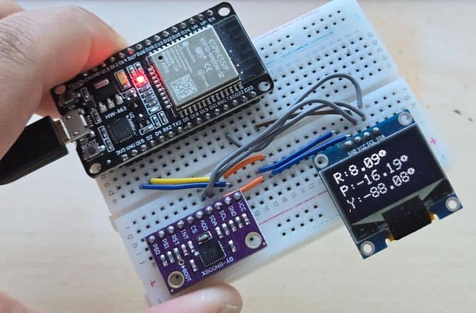
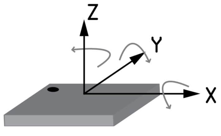
Gently tilt the device forward/backward and left/right to observe changes in pitch and roll. Rotate the device horizontally to see the yaw value update, similar to a compass heading.

For accurate results, move the device slowly in all directions for a few seconds to stabilize the sensor fusion. When the device is stationary, the displayed values should remain steady. I used BNO080 to build an IoT Activity Tracker project. You can read that too.
Video Tutorial & Guide


