

Overview
In this project, we will build a Smart Colorimeter—also called a True Color Analyzer—using the ESP32 and the AS7265x Triad Spectroscopy Sensor. The AS7265x is an advanced 18-channel spectral sensor covering the visible, UV, and near-infrared ranges, enabling accurate color detection and basic material analysis in a compact form.
The ESP32–AS7265x Smart Colorimeter is designed to measure and visualize color information with high precision. It continuously captures spectral data and converts it into user-friendly RGB and HEX color values, all displayed on a clean, real-time web dashboard hosted directly on the ESP32.
This device works as a portable scientific tool for colorimetry, spectral fingerprinting, and general optical monitoring. Its compact design makes it ideal for analyzing pigments, LEDs, textiles, foods, plastics, and various experimental materials—providing a small, practical introduction to real-world spectroscopy.
To get started with Triad Spectroscopy sensor, you can refer to AS7265x Arduino Interfacing guide.
AS7265x Triad Spectroscopy Sensor
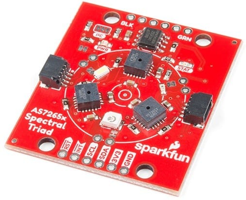
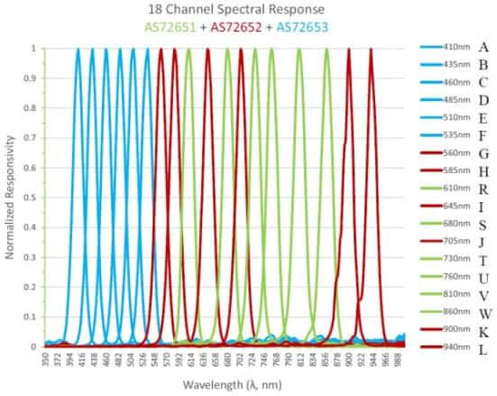
The AS7265x Triad Spectroscopy Sensor is a compact and versatile optical inspection module, often referred to as a desktop spectrophotometer. It combines three independent spectral sensors—the AS72651, AS72652, and AS72653—to deliver 18 calibrated spectral channels ranging from 410 nm (UV) to 940 nm (IR). This wide spectral range enables detailed analysis of how different materials absorb, reflect, or transmit light across visible, ultraviolet, and near-infrared wavelengths.
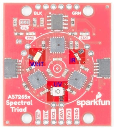
To support professional-quality illumination, the Triad integrates three LEDs positioned around the sensor array:
- A 5700K white LED for general visible-light illumination
- A 405 nm ultraviolet LED
- An 875 nm infrared LED
Each LED can be individually controlled through software, with adjustable drive current, allowing the sensor to illuminate targets under different spectral conditions for more accurate readings.
The Triad is built around three AMS sensors, each responsible for a specific spectral region:
- AS72651 — UV Sensor (Master)
- AS72652 — Visible Light Sensor (Slave)
- AS72653 — Near-Infrared Sensor (Slave)
The AS72651 acts as the master controller, communicating with the other two sensors over a dedicated internal I²C bus. By default, the AS7265x communicates using I²C at address 0x49. After collecting data from all three devices, it combines the spectral measurements and exposes them to the user as a single set of 18 spectral channels, providing a seamless interface for software developers.
The SparkFun Triad includes a 4 Mbit EEPROM, which stores the operational firmware. At power-up, the AS72651 automatically loads the firmware, enabling all sensor functions and coordinated multi-sensor operation. The board also supports a 115200 baud UART serial interface, which uses a simple AT command set for configuring illuminators, reading sensor channels, and adjusting measurement parameters.
Colorimeter Circuit Design & Schematic
Let’s walk through the hardware design of the ESP32 AS7265x-based Smart Colorimeter / True Color Analyzer System in detail.
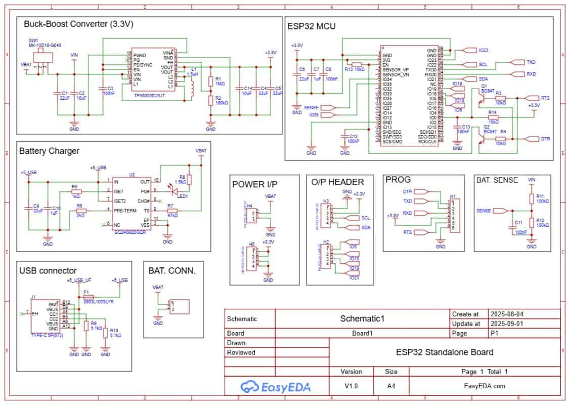
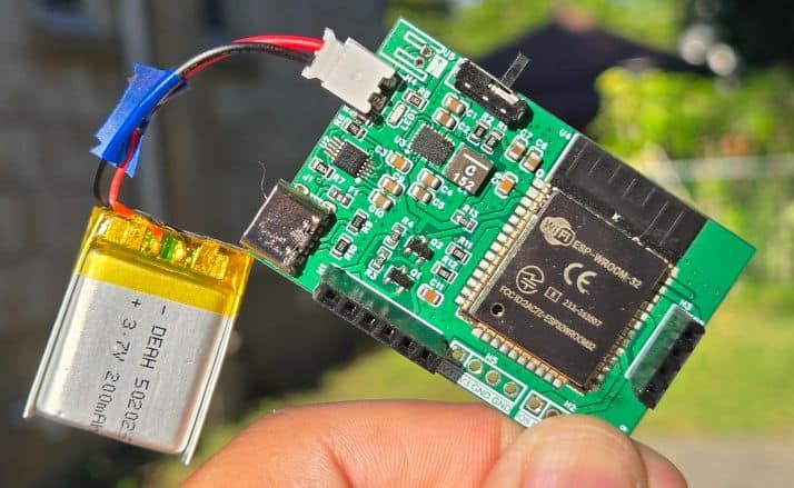
The board is powered through a USB Type-C port. If battery operation is required, charging can be handled by a Li-ion charging IC such as the BQ24092D (or similar). It supports CC/CV charging, pre-conditioning, and auto cut-off. A small LED indicates charging status. A JST-PH connector is used to connect a 3.7 V Li-ion/LiPo battery. A slide switch is added to turn the system on or off.
The regulated 3.3 V supply for the ESP32 and the AS7265x sensor is provided by a buck-boost converter like the TPS63020. It ensures a stable 3.3 V output across the entire battery voltage range (3.0–4.2 V). This keeps the ESP32 and the spectroscopy sensor powered reliably even at low battery levels.
Programming is done through the PROG header or the onboard USB interface using an FTDI adapter (depending on your ESP32 module). Two transistors, Q1 and Q2, handle the auto-reset and auto-boot sequence. This means no buttons are needed during code upload.
Extra GPIO pins are broken out for sensors and modules. IO21 (SDA) and IO22 (SCL) provide the I²C interface for connecting the AS7265x Triad Spectroscopy Sensor, which is the core of the colorimeter system.
- Download: Schematic PDF
- Download: Bill of Materials (BOM)
- Download: Pick & Place File
Project PCB Design, Gerber File & PCB Ordering Online
The schematic of the ESP32 AS7265x was created in EasyEDA, and from there it was converted into a compact PCB layout.
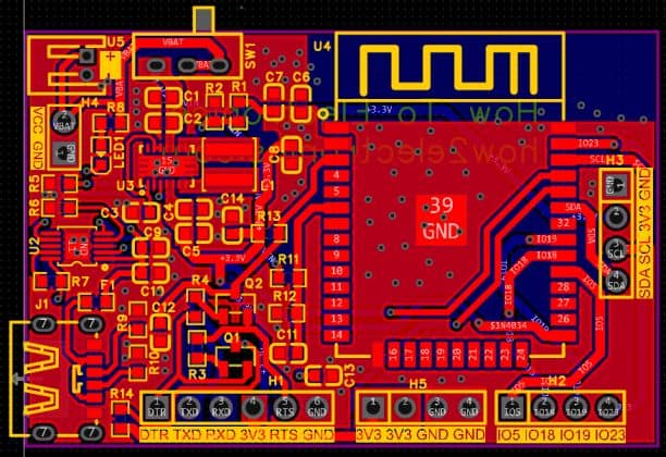
The board is designed with mostly SMD components to keep the size small. Resistors and capacitors are in the 0603 package, while the main ICs, such as the TPS63020 buck-boost converter and the BQ24092D battery charger, are also in SMD form.
All of the critical components, including the ESP32-WROOM module, are placed on the front side of the PCB, which makes assembly easier and more reliable.
The Gerber files for this board are available and can be used to place an order directly with ALLPCB. They offer PCB prototyping services at very low cost, and new users get extra benefits.
Ordering is straightforward: go to the ALLPCB Official Website. Then upload the Gerber files using the Quote Now option, and choose your board parameters like material, dimensions, thickness, quantity, and solder mask color.
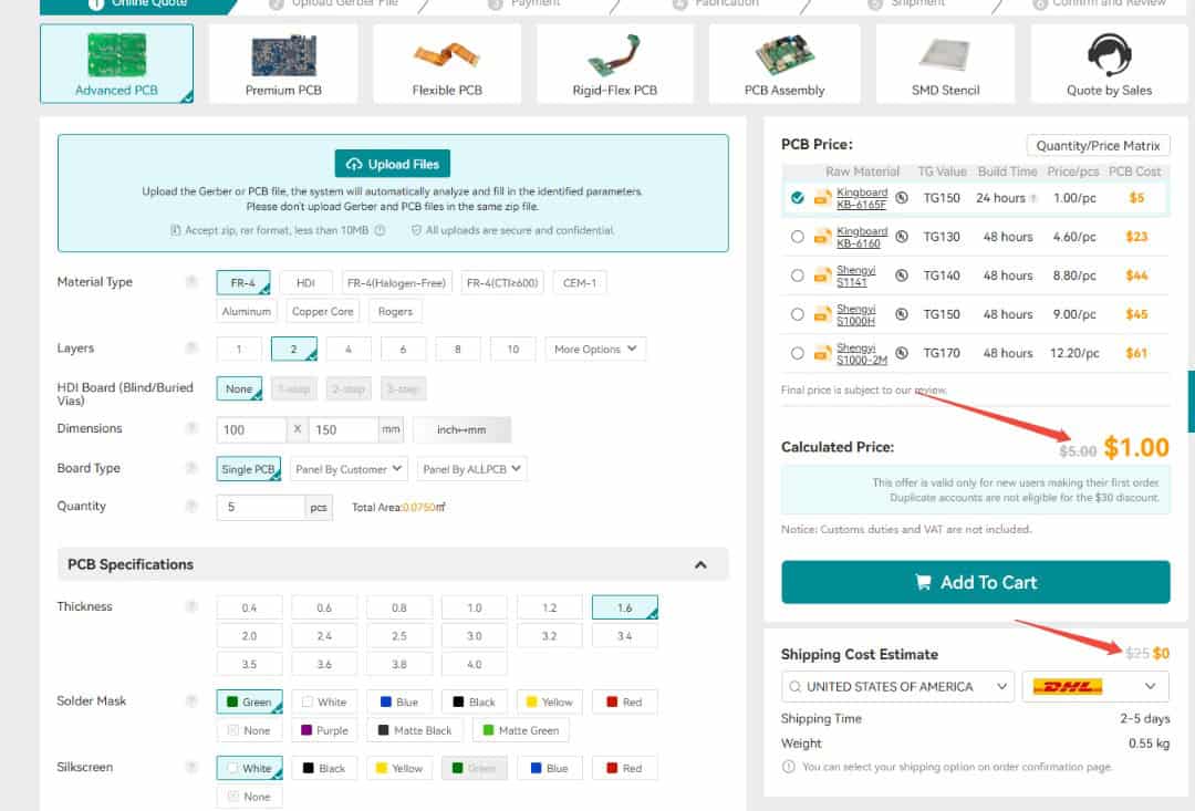
Currently, ALLPCB provides a special promotion for new users — $30 off the first PCB order and $30 off shipping, effectively giving you free shipping with no restrictions on board size, layers, or quantity.

Here is the campaign detail: Unlock $1 PCB Prototyping
Once you finalize the details, select your shipping option, confirm the order, and wait for the boards to be delivered.
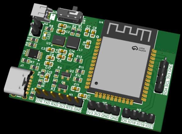
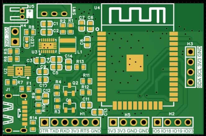
The 3D preview of the PCB design shows the placement of the ESP32, power management ICs, and passive components neatly arranged on the front side.
Assembly & Testing the DIY ESP32 AS7265x Colorimeter Board
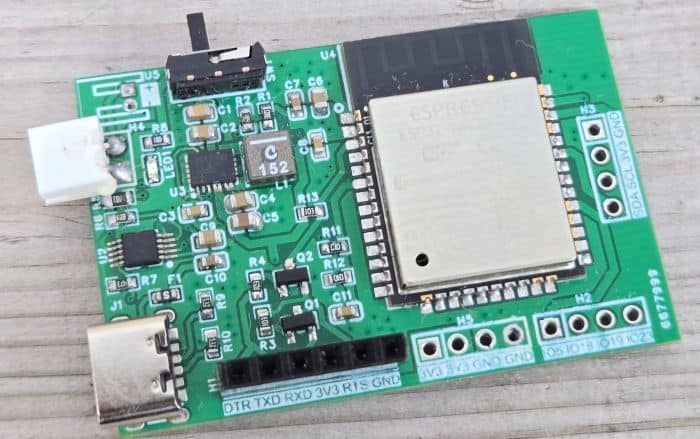
After about a week, the finished PCBs arrived from ALLPCB. The quality was excellent, with smooth solder pads and precise silkscreen printing—perfect for assembling the ESP32 IoT board.
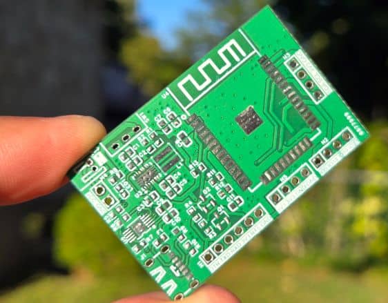
Assembly begins with soldering all the SMD components on the front side. The design is compact, so only the front contains the ESP32 module, buck-boost converter, charger IC, and supporting resistors and capacitors.
In the first prototype there were a few minor value adjustments for capacitors and resistors, but these have been corrected in the final Gerber release, so you can assemble the latest version without any issues.
Once assembled, connect a 3.7 V Li-ion/LiPo battery to the JST connector. Programming the ESP32 is done through the PROG header with an FTDI adapter. Thanks to the automatic reset circuitry, there’s no need to press boot or reset buttons—the upload process is completely automatic.
For charging, simply plug in a USB Type-C cable. A red LED will indicate charging, and you can verify it by checking the battery voltage with a multimeter.
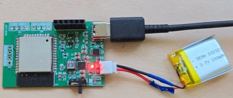
The voltage should gradually increase during charging, confirming that the system is working properly.
Source Code/Program for ESP32 AS7265x Colorimeter
Now let’s move to the coding part. We will develop an Arduino C++ code to interface the AS7265x with the ESP32 and build our Smart Colorimeter / True Color Analyzer.
There is a dedicated library for the AS7265x from SparkFun. First, download the library from the following link and add it to your Arduino libraries folder:
After calculating the final color values, the ESP32 hosts a clean real-time web dashboard using its built-in WiFi capabilities. The webpage uses AJAX to update the RGB and HEX values automatically without refreshing the page, making the colorimeter responsive and easy to use.
The code for this project is divided into two parts: Colorimeter.ino and webpage.h. The webpage file is kept separate as a header file to maintain cleaner organization and isolate all HTML, CSS, and JavaScript code from the main program logic. To run the project, simply copy both files into your Arduino sketch folder—use the .ino file as the main sketch and include the webpage.h file alongside it.
Colorimeter.ino
In the following code you need to change the WiFi SSID and password from the following lines.
|
1 2 3 |
// -------------------- WiFi CONFIG -------------------- const char* ssid = "*********************"; // <-- change this const char* password = "*********************"; // <-- change this |
Here is the final code for Colorimter.ino that you can copy and paste in your Arduino IDE.
|
1 2 3 4 5 6 7 8 9 10 11 12 13 14 15 16 17 18 19 20 21 22 23 24 25 26 27 28 29 30 31 32 33 34 35 36 37 38 39 40 41 42 43 44 45 46 47 48 49 50 51 52 53 54 55 56 57 58 59 60 61 62 63 64 65 66 67 68 69 70 71 72 73 74 75 76 77 78 79 80 81 82 83 84 85 86 87 88 89 90 91 92 93 94 95 96 97 98 99 100 101 102 103 104 105 106 107 108 109 110 111 112 113 114 115 116 117 118 119 120 121 122 123 124 125 126 127 128 129 130 131 132 133 134 135 136 137 138 139 140 141 142 143 144 145 146 147 148 149 150 151 152 153 154 155 156 157 158 159 160 161 162 163 164 165 166 167 168 169 170 171 172 173 174 175 176 177 178 179 180 181 182 183 184 185 186 187 188 189 190 191 192 193 194 195 196 197 198 199 200 201 202 203 204 |
#include <Arduino.h> #include <Wire.h> #include "SparkFun_AS7265X.h" #include <WiFi.h> #include <WebServer.h> #include "webpage.h" // Our HTML page // -------------------- WiFi CONFIG -------------------- const char* ssid = "*********************"; // <-- change this const char* password = "*********************"; // <-- change this // -------------------- GLOBAL OBJECTS -------------------- AS7265X sensor; WebServer server(80); // Latest color values (shared with webserver) uint8_t currentR = 0; uint8_t currentG = 0; uint8_t currentB = 0; String currentHex = "#000000"; // -------------------- HELPERS -------------------- // Map float 0..1 -> 0..255 uint8_t floatToByte(float v) { if (v < 0.0f) v = 0.0f; if (v > 1.0f) v = 1.0f; return (uint8_t)(v * 255.0f + 0.5f); } // Format RGB as "#RRGGBB" void rgbToHex(uint8_t r, uint8_t g, uint8_t b, char* out) { sprintf(out, "#%02X%02X%02X", r, g, b); } // -------------------- WEB HANDLERS -------------------- // Serve the main HTML page void handleRoot() { server.send_P(200, "text/html", INDEX_HTML); } // Serve current color as JSON void handleColor() { char json[80]; snprintf(json, sizeof(json), "{\"r\":%u,\"g\":%u,\"b\":%u,\"hex\":\"%s\"}", currentR, currentG, currentB, currentHex.c_str()); server.send(200, "application/json", json); } void handleNotFound() { server.send(404, "text/plain", "Not found"); } // Initialize WiFi + HTTP server void setupWebServer() { Serial.println(); Serial.println("Connecting to WiFi..."); WiFi.mode(WIFI_STA); WiFi.begin(ssid, password); while (WiFi.status() != WL_CONNECTED) { delay(500); Serial.print("."); } Serial.println(); Serial.print("WiFi connected. IP address: "); Serial.println(WiFi.localIP()); server.on("/", handleRoot); server.on("/color", handleColor); server.onNotFound(handleNotFound); server.begin(); Serial.println("HTTP server started"); } // Call in loop() to keep server responding void handleWebServer() { server.handleClient(); } // -------------------- COLOR SENSOR LOGIC -------------------- // Read AS7265x and compute approximate R,G,B + HEX void readColorFromSensor() { // Take measurement with onboard illumination (same as SparkFun Example2) sensor.takeMeasurementsWithBulb(); // blocking // Visible channels float A = sensor.getCalibratedA(); // 410nm float B = sensor.getCalibratedB(); // 435nm float C = sensor.getCalibratedC(); // 460nm float D = sensor.getCalibratedD(); // 485nm float E = sensor.getCalibratedE(); // 510nm float F = sensor.getCalibratedF(); // 535nm float G = sensor.getCalibratedG(); // 560nm float H = sensor.getCalibratedH(); // 585nm float Rr = sensor.getCalibratedR(); // 610nm float I = sensor.getCalibratedI(); // 645nm float S = sensor.getCalibratedS(); // 680nm float J = sensor.getCalibratedJ(); // 705nm // Group to approximate RGB float blue = (A + B + C + D) / 4.0f; // 410–485 nm float green = (E + F + G) / 3.0f; // 510–560 nm float red = (H + Rr + I + S + J) / 5.0f; // 585–705 nm // Normalize float maxRGB = red; if (green > maxRGB) maxRGB = green; if (blue > maxRGB) maxRGB = blue; float rNorm = 0.0f, gNorm = 0.0f, bNorm = 0.0f; if (maxRGB > 1e-3f) { rNorm = red / maxRGB; gNorm = green / maxRGB; bNorm = blue / maxRGB; } uint8_t R8 = floatToByte(rNorm); uint8_t G8 = floatToByte(gNorm); uint8_t B8 = floatToByte(bNorm); char hex[8]; rgbToHex(R8, G8, B8, hex); // Update globals for webserver currentR = R8; currentG = G8; currentB = B8; currentHex = String(hex); // Debug output to Serial Serial.println("=== Raw visible channels (A..J) ==="); Serial.print("A(410)="); Serial.print(A, 3); Serial.print(" B(435)="); Serial.print(B, 3); Serial.print(" C(460)="); Serial.print(C, 3); Serial.print(" D(485)="); Serial.print(D, 3); Serial.print(" E(510)="); Serial.print(E, 3); Serial.print(" F(535)="); Serial.print(F, 3); Serial.print(" G(560)="); Serial.print(G, 3); Serial.print(" H(585)="); Serial.print(H, 3); Serial.print(" R(610)="); Serial.print(Rr, 3); Serial.print(" I(645)="); Serial.print(I, 3); Serial.print(" S(680)="); Serial.print(S, 3); Serial.print(" J(705)="); Serial.println(J, 3); Serial.println("--- Approximate color ---"); Serial.print("R,G,B (0-255): "); Serial.print(R8); Serial.print(", "); Serial.print(G8); Serial.print(", "); Serial.println(B8); Serial.print("HEX: "); Serial.println(hex); Serial.println(); } // -------------------- ARDUINO SETUP/LOOP -------------------- void setup() { Serial.begin(115200); delay(500); Serial.println("ESP32 + AS7265x Colorimeter Webserver"); Wire.begin(); // default ESP32 pins: SDA=21, SCL=22 if (sensor.begin() == false) { Serial.println("AS7265x not detected. Check wiring. Freezing..."); while (1) { delay(1000); } } sensor.disableIndicator(); // Turn off blue status LED setupWebServer(); } void loop() { // Read sensor and update globals readColorFromSensor(); // Serve any web clients handleWebServer(); // Small delay so we’re not spamming readings too fast delay(500); } |
webpage.h file
Here is the webpage file which is the header file for the above code. Create a separate header file and save it as a webpage.h in the same Arduino folder.
Then copy the following code and paste it on the Arduino header sketch.
|
1 2 3 4 5 6 7 8 9 10 11 12 13 14 15 16 17 18 19 20 21 22 23 24 25 26 27 28 29 30 31 32 33 34 35 36 37 38 39 40 41 42 43 44 45 46 47 48 49 50 51 52 53 54 55 56 57 58 59 60 61 62 63 64 65 66 67 68 69 70 71 72 73 74 75 76 77 78 79 80 81 82 83 84 85 86 87 88 89 90 91 92 93 94 95 96 97 98 99 100 101 102 103 104 105 106 107 108 109 110 111 112 113 114 115 116 117 118 119 120 121 122 123 124 125 126 127 128 129 130 131 132 133 134 135 136 137 138 139 140 141 142 143 144 145 146 147 148 149 150 151 152 153 154 155 156 157 158 159 160 161 162 163 164 165 166 167 168 169 170 171 172 173 174 175 176 177 178 179 180 181 182 183 184 185 186 187 188 189 190 191 192 193 194 195 196 197 198 199 200 201 202 203 204 205 206 207 208 209 210 211 212 213 214 215 216 217 218 219 220 221 222 223 224 225 226 227 228 229 230 231 232 233 234 235 236 237 238 239 240 241 242 243 244 245 246 247 248 249 250 251 252 253 254 255 256 257 258 259 260 261 262 263 264 265 266 267 268 269 270 271 272 273 274 275 276 277 278 279 280 281 282 283 284 285 286 287 288 289 290 291 292 293 294 295 296 297 298 299 300 301 302 303 304 305 306 307 308 309 310 311 312 313 314 315 316 317 318 319 320 321 322 323 324 325 326 327 328 329 330 331 332 333 334 335 336 337 338 339 340 341 342 343 344 345 346 347 348 349 350 351 352 353 354 355 356 357 358 359 360 361 362 363 364 365 366 367 368 369 370 371 372 373 374 375 376 377 378 379 380 381 382 383 384 385 386 387 388 389 390 391 392 393 394 395 396 397 398 399 400 401 402 403 404 405 406 407 408 409 410 411 412 413 414 415 416 417 418 419 420 421 422 423 424 425 426 427 428 429 430 431 432 433 434 435 436 437 438 439 440 441 442 443 444 445 446 447 448 449 450 451 452 453 454 455 |
#ifndef HTML_H #define HTML_H const char INDEX_HTML[] PROGMEM = R"rawliteral( <!DOCTYPE html> <html> <head> <meta charset="UTF-8"> <title>AS7265x Colorimeter - Live RGB Viewer</title> <meta name="viewport" content="width=device-width, initial-scale=1.0"> <style> :root { --bg: #f3f4f8; --card-bg: #ffffff; --border: #e2e5ec; --border-subtle: #edf0f6; --text-main: #111827; --text-muted: #6b7280; --accent: #2563eb; --accent-soft: #e0edff; --radius-lg: 18px; --radius-md: 12px; --shadow-soft: 0 10px 30px rgba(15, 23, 42, 0.08); --mono: "JetBrains Mono", "SF Mono", Consolas, monospace; } * { box-sizing: border-box; margin: 0; padding: 0; } body { background: radial-gradient(circle at top left, #ffffff, var(--bg)); font-family: system-ui, -apple-system, "Segoe UI", sans-serif; margin: 0; padding: 20px; color: var(--text-main); display: flex; justify-content: center; } .shell { width: 100%; max-width: 780px; } .card { background: var(--card-bg); border-radius: var(--radius-lg); border: 1px solid var(--border); box-shadow: var(--shadow-soft); padding: 22px 24px 22px 24px; } @media (min-width: 640px) { .card { padding: 26px 30px 26px 30px; } } /* HEADER */ .header { display: flex; align-items: center; justify-content: space-between; gap: 12px; margin-bottom: 18px; } .title-block { display: flex; flex-direction: column; gap: 4px; } .title { font-size: 1.5rem; font-weight: 600; letter-spacing: 0.01em; display: flex; align-items: center; gap: 8px; } .tag { font-size: 0.7rem; text-transform: uppercase; letter-spacing: 0.08em; padding: 2px 10px; border-radius: 999px; border: 1px solid var(--accent-soft); background: #f5f7ff; color: var(--accent); white-space: nowrap; } .subtitle { font-size: 0.9rem; color: var(--text-muted); } .status-pill { font-size: 0.75rem; padding: 4px 10px; border-radius: 999px; border: 1px solid var(--border); background: #f9fafb; color: var(--text-muted); display: inline-flex; align-items: center; gap: 6px; white-space: nowrap; } .status-dot { width: 8px; height: 8px; border-radius: 999px; background: #16a34a; box-shadow: 0 0 8px rgba(22, 163, 74, 0.7); } /* MAIN GRID */ .grid { display: grid; grid-template-columns: minmax(0, 1.4fr) minmax(0, 1.1fr); gap: 18px; } @media (max-width: 640px) { .grid { grid-template-columns: minmax(0, 1fr); } } /* LEFT: COLOR PREVIEW AREA */ .preview-card { border-radius: var(--radius-lg); border: 1px solid var(--border-subtle); background: linear-gradient(135deg, #f9fafb, #f3f6ff); padding: 14px 14px 16px 14px; } .preview-header { display: flex; justify-content: space-between; align-items: center; margin-bottom: 10px; } .preview-title { font-size: 0.9rem; font-weight: 600; } .preview-caption { font-size: 0.78rem; color: var(--text-muted); } #color-box { width: 100%; height: 130px; border-radius: 14px; border: 1px solid var(--border); background: #e5e7eb; box-shadow: inset 0 0 7px rgba(15, 23, 42, 0.12), 0 8px 20px rgba(148, 163, 184, 0.25); transition: background-color 0.2s ease-out, box-shadow 0.2s ease-out; } .meta-row { display: flex; justify-content: space-between; align-items: center; margin-top: 12px; gap: 10px; } .hex-label { font-size: 0.78rem; color: var(--text-muted); margin-bottom: 2px; } #hex_full { font-family: var(--mono); font-size: 0.95rem; padding: 6px 12px; border-radius: 999px; border: 1px solid var(--border); background: #ffffff; display: inline-block; min-width: 96px; text-align: center; } .interval-chip { font-size: 0.78rem; padding: 4px 10px; border-radius: 999px; background: #f9fafb; border: 1px solid var(--border-subtle); color: var(--text-muted); white-space: nowrap; } /* RIGHT: RGB TABLE AREA */ .table-card { border-radius: var(--radius-lg); border: 1px solid var(--border-subtle); background: #ffffff; padding: 12px 12px 10px 12px; } .table-header { display: flex; justify-content: space-between; align-items: baseline; margin-bottom: 8px; } .table-title { font-size: 0.88rem; font-weight: 600; } .table-subtitle { font-size: 0.78rem; color: var(--text-muted); } table { width: 100%; border-collapse: collapse; font-size: 0.85rem; margin-top: 4px; } th, td { padding: 7px 8px; text-align: center; } th { border-bottom: 1px solid var(--border-subtle); font-weight: 600; color: #4b5563; } td { border-bottom: 1px solid var(--border-subtle); } tbody tr:last-child td { border-bottom: none; } .left { text-align: left; padding-left: 4px; } .channel-label { display: inline-flex; align-items: center; gap: 6px; font-size: 0.82rem; font-weight: 500; } .swatch { width: 14px; height: 14px; border-radius: 999px; border: 1px solid #e5e7eb; } .swatch-red { background: #ef4444; } .swatch-green { background: #22c55e; } .swatch-blue { background: #3b82f6; } .mono { font-family: var(--mono); } /* FOOTER */ .footer { margin-top: 16px; text-align: center; font-size: 0.8rem; color: var(--text-muted); } .footer span { color: var(--accent); font-weight: 600; } </style> </head> <body> <div class="shell"> <div class="card"> <!-- HEADER --> <div class="header"> <div class="title-block"> <div class="title"> AS7265x Colorimeter <span class="tag">ESP32 Webserver</span> </div> <div class="subtitle"> Live RGB estimation from multi-channel spectroscopy readings. </div> </div> <div class="status-pill"> <span class="status-dot"></span> Live · Auto-refresh </div> </div> <!-- MAIN CONTENT --> <div class="grid"> <!-- LEFT: Color preview --> <div class="preview-card"> <div class="preview-header"> <div> <div class="preview-title">Measured color</div> <div class="preview-caption">Preview box reflects the current HEX value.</div> </div> </div> <div id="color-box"></div> <div class="meta-row"> <div> <div class="hex-label">HEX (combined RGB)</div> <div id="hex_full">#------</div> </div> <div class="interval-chip"> Refresh interval: 500 ms </div> </div> </div> <!-- RIGHT: RGB details table --> <div class="table-card"> <div class="table-header"> <div class="table-title">Channel details</div> <div class="table-subtitle">Instantaneous RGB values</div> </div> <table> <thead> <tr> <th class="left">Channel</th> <th>0–255</th> <th>HEX</th> </tr> </thead> <tbody> <tr> <td class="left"> <span class="channel-label"> <span class="swatch swatch-red"></span> Red </span> </td> <td id="r_dec" class="mono">-</td> <td id="r_hex" class="mono">-</td> </tr> <tr> <td class="left"> <span class="channel-label"> <span class="swatch swatch-green"></span> Green </span> </td> <td id="g_dec" class="mono">-</td> <td id="g_hex" class="mono">-</td> </tr> <tr> <td class="left"> <span class="channel-label"> <span class="swatch swatch-blue"></span> Blue </span> </td> <td id="b_dec" class="mono">-</td> <td id="b_hex" class="mono">-</td> </tr> </tbody> </table> </div> </div> <!-- FOOTER --> <div class="footer"> Data endpoint: <span>/color</span> · JSON · Designed for AS7265x + ESP32 </div> </div> </div> <script> function padHex(v) { return ("0" + Number(v).toString(16)).slice(-2).toUpperCase(); } function updateColor() { fetch('/color') .then(resp => resp.json()) .then(data => { // Decimal document.getElementById('r_dec').textContent = data.r; document.getElementById('g_dec').textContent = data.g; document.getElementById('b_dec').textContent = data.b; // Per-channel HEX document.getElementById('r_hex').textContent = "#" + padHex(data.r) + "0000"; document.getElementById('g_hex').textContent = "#00" + padHex(data.g) + "00"; document.getElementById('b_hex').textContent = "#0000" + padHex(data.b); // Combined HEX document.getElementById('hex_full').textContent = data.hex; // Color box const box = document.getElementById('color-box'); box.style.backgroundColor = data.hex; box.style.boxShadow = "inset 0 0 7px rgba(15,23,42,0.12), 0 8px 20px " + data.hex + "33"; }) .catch(err => console.log(err)); } updateColor(); setInterval(updateColor, 500); </script> </body> </html> )rawliteral"; #endif |
Device Testing and Operations
Once the hardware assembly is complete, connect the battery. Also connect the AS7265x sensor to the I2C port of the hardware.
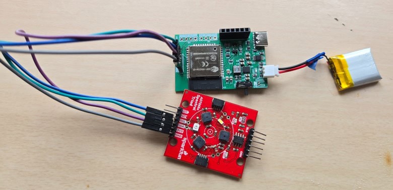
To upload the code, connect your FTDI module directly to the PROG header on the PCB.
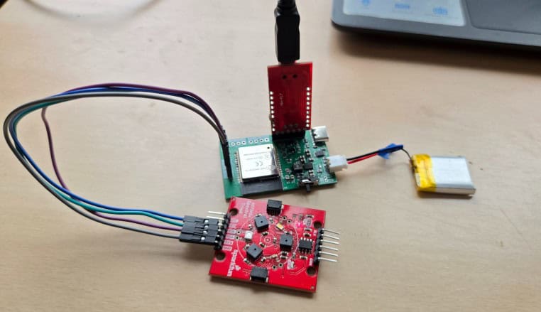
On your Arduino IDE, from the Tools → Board Manager, select ESP32 Dev Module as the board type, and also choose the correct COM port corresponding to your FTDI adapter.
Finally, click the Upload button. The code will be automatically uploaded to your ESP32 board without the need to press any reset or boot buttons.
After successfully uploading the sketch, open the Serial Monitor in the Arduino IDE. Make sure the baud rate is set to 115200.
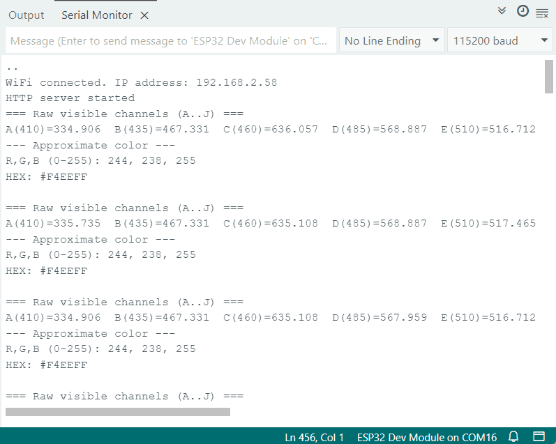
The Serial Monitor displays all 18 calibrated spectral readings from the AS7265x along with the computed RGB (0–255) values and the final HEX color code. It also prints the IP address of the ESP32’s local webserver, allowing you to open the real-time dashboard in any browser.
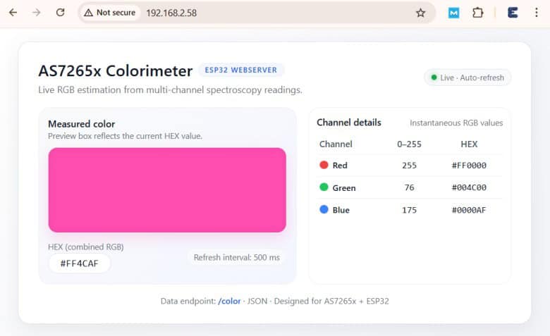
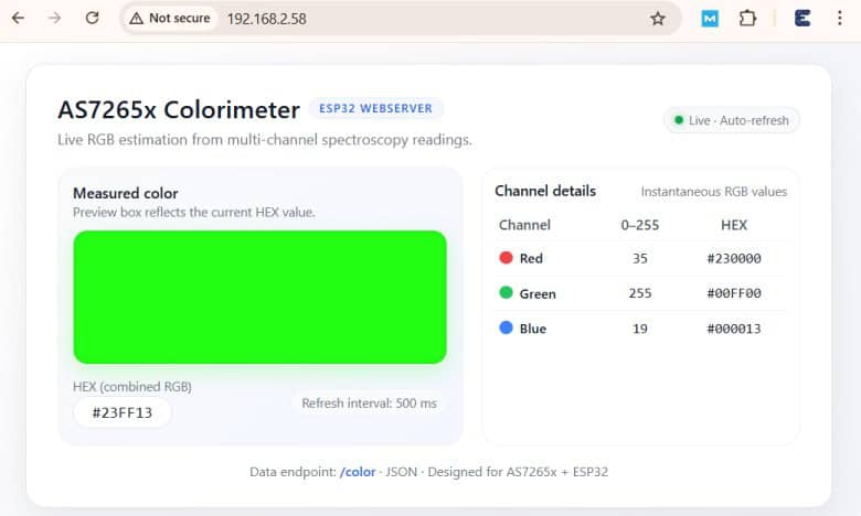
Enter the IP Address on any Web Browser. And following page will appear.
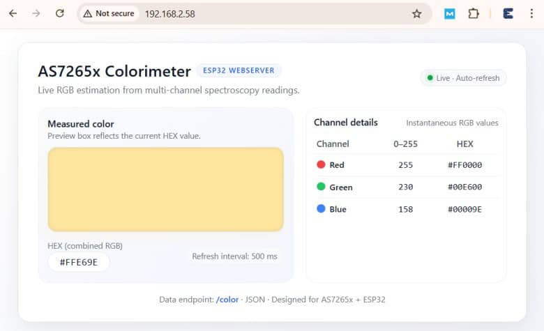
The page displays a large live color preview box, along with the calculated RGB (0–255) values and corresponding HEX color code in a neatly formatted table. Using AJAX, the webpage updates automatically every 500 ms without refreshing, showing real-time color changes as the sensor reads new data.
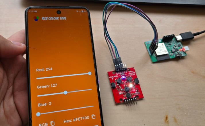
To test color detection, use any RGB Color App from the Play Store that can display different solid colors on your phone screen.
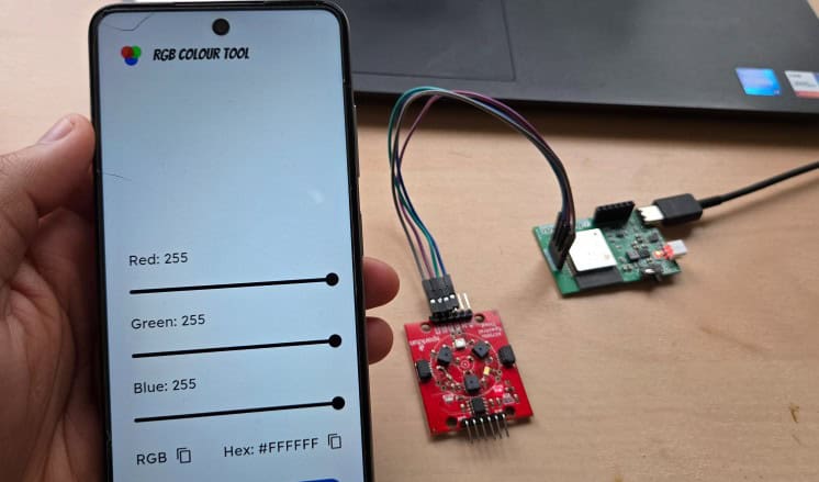
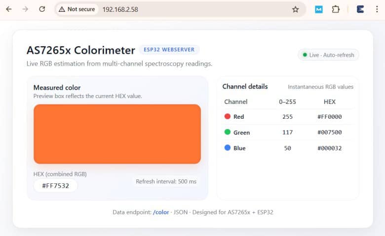
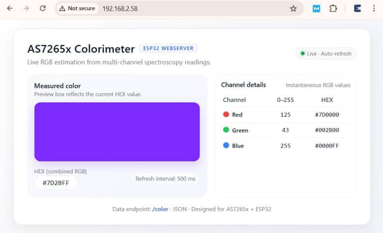
Place the phone screen directly over the AS7265x sensor, and the system will read the reflected light and display the corresponding RGB and HEX values on both the Serial Monitor and the live web dashboard.
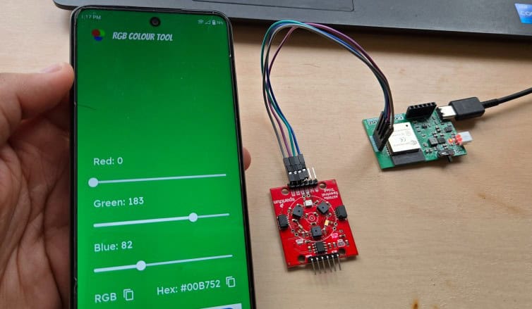
You can test primary colors like red, green, and blue, as well as mixed or pastel shades to observe how precisely the system tracks subtle variations.
Try adjusting the distance or brightness of the screen to see how illumination affects the readings.
You can also test real-world objects—such as papers, fabrics, plastic items, or LED lights—to evaluate how well the colorimeter performs outside of controlled digital displays.
Video Tutorial & Guide


