

Overview
In this tutorial, we will learn interfacing of MPU6050 Accelerometer & Gyroscope Sensor with Arduino R4 Minima Board. The MPU6050 is a versatile and widely-used sensor that combines a 3-axis gyroscope and a 3-axis accelerometer, making it ideal for numerous motion-sensing applications.
The MPU6050 can be used with Arduino to calculate acceleration is all the X, Y and Z axis. It can also be used to measure the angular velocity. When the accelerometer data, gyroscope data and magnetometer data are combined together, the pitch, roll, yaw value can be calculated. The guide covers the measurement of acceleration, angular velocity, temperature as well as pitch, roll, yaw calculation by interfacing MPU6050 with Arduino. You may take a look at the BMI160 which is an advanced Gyroscope Accelerometer module from Bosch.
Bill of Materials
For this tutorial I am using the SunFounder Arduino Starter Kit which has 90+ components.
Here are the list of components I am using from this Kit.
| S.N. | Components | Quantity | Purchase Links |
|---|---|---|---|
| 1 | Arduino UNO R4/R3 Board | 1 | Amazon | AliExpress |
| 2 | MPU6050 Gyroscope Accelerometer | 1 | Amazon | AliExpress | SunFounder |
| 5 | Connecting Wires | 10 | Amazon | AliExpress | SunFounder |
| 6 | Type C USB Cable | 1 | Amazon | AliExpress |
| 7 | Breadboard | 1 | Amazon | AliExpress | SunFounder |
MPU6050 Accelerometer & Gyroscope Module
The MPU-6050, a motion tracking device, integrates a 3-axis gyroscope with a 3-axis accelerometer, making it a 6-axis sensor.

This device is capable of detecting variations in movement, acceleration, and rotational dynamics. It’s frequently utilized in areas like robotics, game controllers, and various other electronics that necessitate motion sensing. Due to its precise performance and affordability, it is highly favored in the DIY enthusiast circle. You may refer to MPU6050 Datasheet from Invensense for detailed information.
Working Principle
The MPU-6050 sensor module is equipped with a 3-axis accelerometer and a 3-axis gyroscope.
To understand its coordinate systems, place the MPU6050 flat on a table with the labeled side facing up and a dot on the upper left corner of this surface.
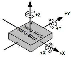
In this position, the vertical direction pointing upwards defines the chip’s Z-axis. The horizontal direction stretching from left to right is identified as the X-axis. Correspondingly, the direction extending from the back of the chip towards the front is designated as the Y-axis.
3-axis Accelerometer
The accelerometer in the MPU6050 operates based on the piezoelectric effect, where certain materials produce an electric charge when subjected to mechanical stress.
Visualize a cuboidal box containing a small ball, similar to the illustration. The walls of this box are constructed from piezoelectric crystals. When the box is tilted, gravity causes the ball to move towards the tilt direction. Upon colliding with a wall, the ball generates minute piezoelectric currents. In this cuboid, there are three pairs of opposite walls, each pair representing an axis in 3D space: the X, Y, and Z axes. The currents from the piezoelectric walls indicate the tilt direction and its intensity.
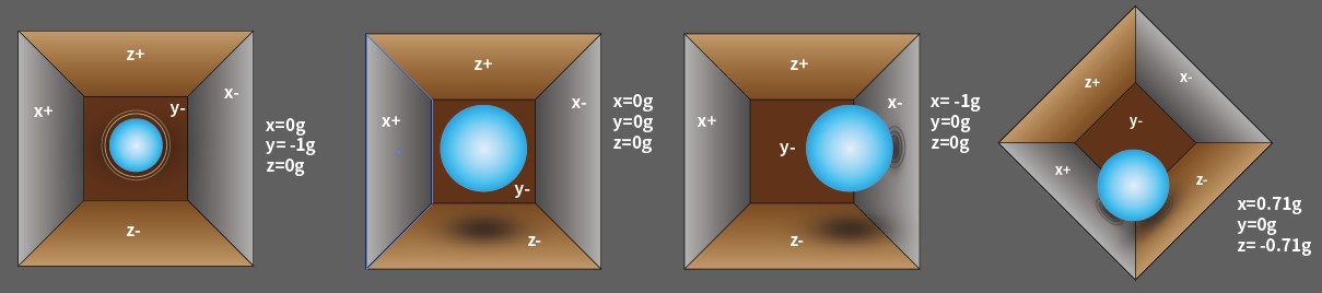
Using the MPU6050, acceleration along each coordinate axis can be detected. In a stationary position on a desk, the Z-axis acceleration measures 1 gravity unit, while the X and Y axes register 0. If the sensor is tilted or experiences weightlessness or overload, the readings alter accordingly.
The MPU6050 offers four selectable measurement ranges: ±2g, ±4g, ±8g, and ±16g (default is ±2g), each providing a specific precision level. The values span from -32768 to 32767.
The accelerometer’s output is converted into an acceleration value by mapping the raw data from the reading range to the measurement range, using the formula:
For example, consider the X-axis with a raw data reading of 16384 and a ±2g range:
3-axis Gyroscope
Gyroscopes in devices like the MPU6050 operate based on the principle of Coriolis acceleration. Picture a fork-like structure in a continuous back-and-forth motion, anchored using piezoelectric crystals. When this setup is tilted, the crystals experience a force in the tilt direction, a result of the inertia from the moving fork. This force leads the crystals to generate an electric current through the piezoelectric effect, which is then amplified.

The gyroscope, similar to the accelerometer, offers four measurement ranges: ±250, ±500, ±1000, and ±2000 degrees per second. The method of calculation and the principle of operation are largely analogous to those of the accelerometer.
The formula to convert the gyroscope’s raw data into angular velocity is:
For instance, if the gyroscope’s raw data along the X axis is 16384 and the range is ±250°/s, the calculation for angular velocity along the X axis would be:
Features of MPU6050
- 3.3/5V Working voltage
- I2C Interface (up to 400Kb/s)
- Acceleration measurement range: ±2/±4/±8/±16g
- Gyroscope measurement range: ±250/±500/±1000/±2000°/s
- ADC resolution: 16bit
- Resolution: ACC:16384LSB/g(Max), Gyro:131LSB/(°/s)(Max)
- Output Speed: ACC: 1KHz(Max), Gyro: 8KHz(Max)
- Output rate of attitude solution:200Hz
- Working temperature: -40℃~85℃
- Size: 16x18mm
MPU6050 Pinout
The MPU-6050 module has 8 pins:

- INT: Interrupt digital output pin.
- AD0: I2C Slave Address LSB pin. This is the 0th bit in 7-bit slave address of device. If connected to VCC then it is read as logic one and slave address changes.
- XCL: Auxiliary Serial Clock pin. This pin is used to connect other I2C interface enabled sensors SCL pin to MPU-6050.
- XDA: Auxiliary Serial Data pin. This pin is used to connect other I2C interface enabled sensors SDA pin to MPU-6050.
- SCL: Serial Clock pin. Connect this pin to microcontrollers SCL pin.
- SDA: Serial Data pin. Connect this pin to microcontrollers SDA pin.
- GND: Ground pin. Connect this pin to ground connection.
- VCC: Power supply pin. Connect this pin to +5V DC supply.
Interfacing MPU6050 Accelerometer & Gyroscope with Arduino
Now let us interface MPU6050 Accelerometer & Gyroscope Module with Arduino R4 Board. Here is the connection diagram.

The connection is very simple as shown above:
- VCC: Connect to the 3.3V on the Arduino.
- GND: Connect to the Ground (GND) on the Arduino.
- SCL: Connect to the A5 pin of your Arduino.
- SDA: Connect to the A4 pin of your Arduino.

You can use a breadboard for assembly and jumper wires for connection.
Reading Accelerometer, Gyroscope & Temperature Data from MPU6050
After the hardware setup is complete, we can move to the coding part of this project. In this example, we will be particularly emphasizing accelerometer, gyroscope, and temperature data reading.
The Accelerometer data can be read and converted to common units like meters per second squared (m/s^2). Gyroscope data is typically in degrees per second. The temperature sensor data can be used for calibrating other sensor readings.
The code requires Adafruit MPU6050 Library for compilation. Therefore add the library to the Arduino library folder. Here is the complete code for reading the accelerometer, gyroscope and temperature data by interfacing MPU6050 with Arduino R4 Board.
|
1 2 3 4 5 6 7 8 9 10 11 12 13 14 15 16 17 18 19 20 21 22 23 24 25 26 27 28 29 30 31 32 33 34 35 36 37 38 39 40 41 42 43 44 45 46 47 48 49 50 51 52 53 54 55 56 57 58 59 60 61 62 63 64 65 66 67 68 |
// Include the necessary libraries #include <Adafruit_MPU6050.h> #include <Adafruit_Sensor.h> #include <Wire.h> // Create an object for the MPU6050 sensor Adafruit_MPU6050 mpu; void setup() { // Initialize the serial communication Serial.begin(9600); // Check if the MPU6050 sensor is detected if (!mpu.begin()) { Serial.println("Failed to find MPU6050 chip"); while (1) { delay(10); } } Serial.println("MPU6050 Found!"); // set accelerometer range to +-8G mpu.setAccelerometerRange(MPU6050_RANGE_8_G); // set gyro range to +- 500 deg/s mpu.setGyroRange(MPU6050_RANGE_500_DEG); // set filter bandwidth to 21 Hz mpu.setFilterBandwidth(MPU6050_BAND_21_HZ); // Add a delay for stability delay(100); } void loop() { // Get new sensor events with the readings sensors_event_t a, g, temp; mpu.getEvent(&a, &g, &temp); // Print out the acceleration readings in m/s^2 Serial.print("Acceleration: X:"); Serial.print(a.acceleration.x); Serial.print(", Y:"); Serial.print(a.acceleration.y); Serial.print(", Z:"); Serial.print(a.acceleration.z); Serial.println(" (m/s^2)"); // Print out the rotation readings in rad/s Serial.print("Rotation: X:"); Serial.print(g.gyro.x); Serial.print(", Y:"); Serial.print(g.gyro.y); Serial.print(", Z:"); Serial.print(g.gyro.z); Serial.println(" (rad/s)"); // Print out the temperature reading in degrees Celsius Serial.print("Temperature: "); Serial.print(temp.temperature); Serial.println(" (degC)"); // Add a blank line for readability Serial.println(""); // Add a delay to avoid flooding the serial monitor delay(250); } |
From the board manager, select the Arduino UNO Board and the respective COM port. Then finally upload the code.
Open the Serial Monitor.

The Serial Monitor should start displaying the accelerometer, gyroscope, and temperature readings from the MPU6050 sensor. These readings are shown in real-time and update continuously.

Move the MPU6050 sensor to see changes in the accelerometer and gyroscope data. The accelerometer data should change with the orientation of the sensor, and the gyroscope data should change with the motion. The temperature reading is usually fairly stable.
Reading Pitch, Roll, Yaw Values from MPU6050
In this example we will use the MPU6050 with Arduino to measure the pitch, roll, yaw values. To calculate the pitch, roll, and yaw values using the MPU6050 sensor, we’ll integrate the gyroscope data for yaw and use the accelerometer data for pitch and roll calculations.
The yaw value calculated is relative and prone to drift over time due to the gyroscope’s inherent noise and bias. To fix this issue, we need to accurately calculate the change in yaw over each loop iteration by taking into account potential biases and noise in the gyroscope data. This can be achieved by calibrating the gyroscope at the start and then subtracting this bias from each reading.
Here is the complete code:
|
1 2 3 4 5 6 7 8 9 10 11 12 13 14 15 16 17 18 19 20 21 22 23 24 25 26 27 28 29 30 31 32 33 34 35 36 37 38 39 40 41 42 43 44 45 46 47 48 49 50 51 52 53 54 55 56 57 58 59 60 61 62 63 64 65 66 67 68 69 70 71 72 73 74 |
#include <Adafruit_MPU6050.h> #include <Adafruit_Sensor.h> #include <Wire.h> Adafruit_MPU6050 mpu; float yaw = 0.0; unsigned long lastTime = 0; float gyroBiasZ = 0.0; void setup() { Serial.begin(9600); if (!mpu.begin()) { Serial.println("Failed to find MPU6050 chip"); while (1) { delay(10); } } Serial.println("MPU6050 Found!"); mpu.setAccelerometerRange(MPU6050_RANGE_8_G); mpu.setGyroRange(MPU6050_RANGE_500_DEG); mpu.setFilterBandwidth(MPU6050_BAND_21_HZ); calibrateGyro(); lastTime = millis(); delay(100); } void calibrateGyro() { const int numReadings = 100; gyroBiasZ = 0.0; for (int i = 0; i < numReadings; i++) { sensors_event_t a, g, temp; mpu.getEvent(&a, &g, &temp); gyroBiasZ += g.gyro.z; delay(10); } gyroBiasZ /= numReadings; } void loop() { sensors_event_t a, g, temp; mpu.getEvent(&a, &g, &temp); float ax = a.acceleration.x; float ay = a.acceleration.y; float az = a.acceleration.z; float pitch = atan2(ay, sqrt(ax * ax + az * az)) * 180.0 / PI; float roll = atan2(-ax, az) * 180.0 / PI; unsigned long currentTime = millis(); float deltaTime = (currentTime - lastTime) / 1000.0; float gyroZ = g.gyro.z - gyroBiasZ; // Subtract bias yaw += gyroZ * deltaTime; lastTime = currentTime; Serial.print("Pitch: "); Serial.print(pitch); Serial.println(" degrees"); Serial.print("Roll: "); Serial.print(roll); Serial.println(" degrees"); Serial.print("Yaw: "); Serial.print(yaw); Serial.println(" degrees"); Serial.println(""); delay(250); } |
Upload the code to the Arduino Board.
Open the Serial Monitor. Once the Serial Monitor is active, it will begin displaying the calculated pitch, roll, and yaw values derived from the MPU6050 sensor data. These values are updated in real-time and will continuously refresh to reflect the sensor’s current orientation and motion.
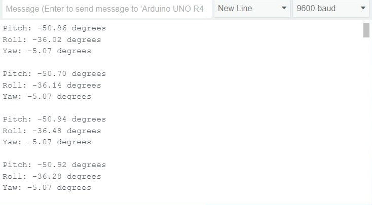
To test the pitch and roll, gently tilt the MPU6050 sensor in different directions. As you do this, observe the changes in the pitch and roll readings:
- Pitch: This value changes as you tilt the sensor forward or backward. A forward tilt should increase the pitch value, while a backward tilt decreases it.
- Roll: This value alters as you tilt the sensor to the left or right. Tilting it to the right increases the roll value, and tilting it to the left decreases it.

For testing the yaw:
- Yaw: Rotate the sensor around its vertical axis (imagine a line running from the top to the bottom of the sensor). This motion should change the yaw value. Note that without a magnetometer, the yaw reading might drift over time, especially if the sensor is rotated rapidly or frequently. You can follow the ESP32 MPU6050 HMC5883L tutorial to calculate the Yaw data properly with the implementation of Kalman Filter.
Some More Examples Projects
The above two examples with Arduino are enough to learn about MPU6050 Gyroscope, Accelerometer & Temperature sensor. Here are the list of some projects you can do using this sensor:

")


