

Overview
In this project, we will make an 300W, 50/60 Hz Inverter using IC SG3525 with PWM Inverter Circuit. The circuit will take a 12V DC power supply from a 12V battery and converts it into 220V, 300W PWM output. An inverter is an electronic device that converts direct current (DC) electricity into alternating current (AC) electricity. It is commonly used to power AC devices from a DC source such as a battery or solar panels. Earlier we made CD4047 Inverter which you can follow for reference.
The SG3525 is a pulse width modulation (PWM) control integrated circuit (IC) used in switching power supplies and inverters. It is designed to control the output voltage and frequency of a DC-AC converter and can be used in a variety of applications such as motor control, lighting, and uninterruptible power supplies (UPS). The SG3525 provides a means of regulating the output voltage and frequency by adjusting the duty cycle of the PWM signal. It also includes protection features such as over-current and thermal shutdown.
Bill of Materials
We need the following components to make an SG3525 Inverter Circuit. You can purchase all these components online from the links given.
| S.N. | Components | Quantity | Purchase Links |
|---|---|---|---|
| 1 | SG3525 IC | 1 | AliExpress |
| 2 | IRF520 MOSFET | 2 | Amazon | AliExpress |
| 3 | Resistor 10K | 6 | Amazon | AliExpress |
| 4 | Resistor 4.7K | 1 | Amazon | AliExpress |
| 5 | Resistor 47Ω | 1 | Amazon | AliExpress |
| 6 | Resistor 10Ω | 2 | Amazon | AliExpress |
| 7 | Variable Resistor 50K | 1 | Amazon | AliExpress |
| 8 | Capacitor 1000uF | 1 | Amazon | AliExpress |
| 9 | Capacitor 1uF | 2 | Amazon | AliExpress |
| 10 | Capacitor 0.1uF | 1 | Amazon | AliExpress |
| 11 | LED 5mm Red | 1 | Amazon | AliExpress |
| 12 | 2 Pin Terminal Block | 1 | Amazon | AliExpress |
| 13 | 3 Pin Terminal Block | 1 | Amazon | AliExpress |
| 14 | 12V Lead Acid Battery | 1 | Amazon | AliExpress |
| 15 | 12-0-12 Transformer | 1 | Amazon | AliExpress |
SG3525 Regulating Pulse Width Modulators

The SG3525 is a control integrated circuit that is used in switched-mode power supplies, DC-DC converters, AC-DC power supplies, and motor drives. The purpose of a PWM controller like the SG3525 is to generate a rectangular waveform that can be used to control the power delivered to a load. The SG3525 has several internal blocks that work together to achieve this:
- Voltage reference: This is an internal voltage source that provides a stable and precise reference voltage to the error amplifier.
- Error amplifier: This is a differential amplifier that compares the output voltage to the reference voltage. The error amplifier generates an error signal proportional to the difference between the two voltages.
- Oscillator: This is an internal timer that generates the clock signal that sets the switching frequency of the PWM waveform. The frequency can be set by an external resistor and capacitor.
- Control circuitry: This includes the logic that implements the PWM control algorithm, taking the error signal from the error amplifier and the clock signal from the oscillator to generate the PWM waveform.
The SG3525 also has several features, such as soft-start, under-voltage lockout, and over-current protection, that make it suitable for use in demanding applications. By adjusting the parameters of the error amplifier, oscillator, and control circuitry, the SG3525 can be used to control the output voltage, current, or power of a load, making it a versatile and cost-effective solution for many power control applications. Refer to SG3525 Datasheet for more details.
Designing of SG3525 PWM Inverter Circuit
Let us take a look at the SG3525 PWM Inverter Circuit diagram and discuss its designing principle.

SG3525 can control the output voltage of the inverter. It is also useful in driving MOSFET IRF520 connected to a transformer. Both MOSFET is used as a low-side connection. The SG3525 has a built-in Totem Pole Circuit to drive low-side connected MOSFETs. Totem pole is basically an output driver circuit used to convert one level of voltage into another level of voltage.
Pins 1 and 2 are the inputs to the onboard error amplifier. When the voltage on the Inverting Input (pin 1) is greater than the voltage on the Non-Inverting Input (pin 2), the duty cycle is decreased. When the voltage on the Non-Inverting Input (pin 2) is greater than the voltage on the Inverting Input (pin 1), the duty cycle is increased.
The frequency of PWM is dependent on the timing capacitance and the timing resistance. The timing capacitor (CT) is connected between pin 5 and the ground. The timing resistor (RT) is connected between pin 6 and the ground. The resistance between pins 5 and 7 (RD) determines the dead time. The frequency is related to RT, CT, and RD by the relationship:
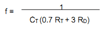
RT must be within the range of 2kΩ to 150kΩ. CT must be within the range of 1nF to 0.2µF. The oscillator frequency must be within the range 100Hz to 400kHz. If you are looking to use this for a 50Hz inverter, you require drive signals of 50Hz. So, the oscillator frequency must be 100Hz. A capacitance connected between pin 8 and the ground provides the soft-start functionality. The larger the capacitance, the larger the soft-start time.
Pin 16 is the output from the voltage reference section. This reference is often used to provide a reference voltage to the error amplifier for setting the feedback reference voltage. Pin 15 is VCC – the supply voltage to the SG3525 that makes it run. VCC must lie within the range of 8V to 35V.
Pins 11 and 14 are the outputs from which the drive signals are to be taken. They are the outputs of the SG3525 internal driver stage and can be used to directly drive MOSFETs and IGBTs. They have a continuous current rating of 100mA and a peak rating of 500mA. Pin 10 is shut down. When this pin is low, PWM is enabled. When this pin is high, the PWM latch is immediately set.
Note: The circuit is capable of generating 300W PWM output. For this use 75NF75 MOSFET. The Maximum Power of 75NF75 MOSFET is 300 W. Therefore you need Power Transformer 12-0-12V, with a 3 Ampere of 5 Ampere current rating. The power source should be 12V, 5A in this case.
SG3525 Inverter PCB Gerber File & Ordering PCB Online
If you don’t want to assemble the circuit on a zero PCB or a breadboard and you want PCB for the project, then here is the PCB for you. I used EasyEDA to draw the schematic first. Then I converted the schematic to PCB. The PCB Board for this project looks something like below.

The Gerber File for the PCB is given below. You can simply download the Gerber File and order the PCB from ALLPCB at 1$ only.
You can use this Gerber file to order high quality PCB for this project. To do that visit the ALLPCB official website by clicking here: https://www.allpcb.com/.

You can now upload the Gerber File by choosing the Quote Now option. From these options, you can choose the Material Type, Dimensions, Quantity, Thickness, Solder Mask Color and other required parameters.

After filling all details, select your country and shipping method. Finally you can place the order.

The 3D view of the PCB is simply amazing which should look in real after assembling all the components on a PCB.
Hardware Assembly
For the demo and testing purpose, I used zero PCB to assemble the circuit. Here is the PCB Assembly on Zero PCB as per the circuit diagram.

The front side of the PCB Board looks cool but while looking at the back side of the board, the connection is too messy.
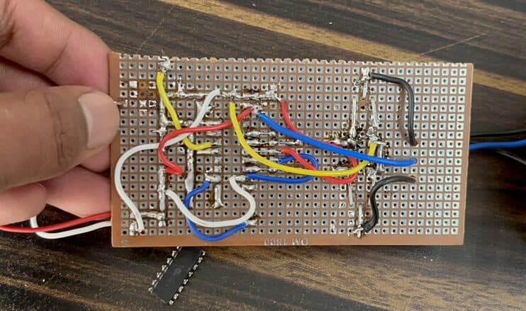
That is why it is best practice to use PCB for the project in order to avoid messy and wrong connection sometimes.
After assembling the components, you can connect a 12-0-12 Transformer at the output terminal. To get more power up to 300W, use a transformer of 12V with 5A current rating.

Connect a 12V,7A Lead-Acid Battery at the input terminal for maximum power. You may try 11.1V Lipo Battery or any other power supply with a similar value.
Testing the SG3525 PWM Inverter Circuit
Now lets test the SG3525 Inverter Circuit. To test it, connect any load such as Bulb, CFL, or AC Fan at the output of the transformer.

The bulb glows and Fan turns on immediately. You may try some other load with a higher power rating.

Using the multimeter, you may test the voltage at the input and the output. At input, it shows a battery voltage of almost 12V and at output across the transformer, it shows a voltage of 220V.

Inverters require sufficient battery capacity, as the power consumption battery will be significant. For testing you may use Lipo or Lithium-Ion Battery but for real-life applications use a 12V, 7Ah Lead Acid Battery. You can also adjust the output voltage of the inverter by adjusting the 50K trim pot on the PCB board.
Some common applications for a 300W inverter include running small appliances in a vehicle, powering lights or devices during a power outage, or as a backup power source for outdoor activities or camping.
Video Tutorial & Guide


1 Comment
hi i made this circuit but i have a problem i the output a/c is 0 to 5 volts a/c not 12v a/c as intented? what could be the cause ??