

Overview
In this project, we will build a Smart Blind Stick using the Op-Amp IC LM358 and an IR Sensor. Earlier we build a Smart Blind Stick using Arduino & Ultrasonic Sensor HC-SR04. The project worked very well.
But today, we are going to do the same project without the use of any microcontroller. For this we will simply use an Op-Amp IC LM358. This device helps visually impaired people by detecting obstacles in their way. The IR sensor sends and receives infrared signals to spot obstacles, and the LM358 processes these signals to trigger an alert, making it easier and safer for them to move around.
Bill of Materials
Following are the components required for building this DIY Smart Blind Stick project.
| ID | Name | Designator | Quantity |
|---|---|---|---|
| 1 | Capacitor 100nF | C10,C9 | 2 |
| 2 | Resistor 1K | R7 | 1 |
| 3 | Resistor 10K | R8,R5 | 2 |
| 4 | Resistor10K | 10K _ POTENTIOMETER | 1 |
| 5 | Switch SW1 | SWITCH | 1 |
| 6 | IR LED | LED 2 | 1 |
| 7 | Photo Diode | LED 1 | 1 |
| 8 | LED Red | LED 3 | 2 |
| 9 | BAT Connector | P3 | 1 |
| 10 | TP4056 | U25 | 1 |
| 11 | 3.7V Lipo Battery | BAT_500MAH | 1 |
| 12 | LM358P IC | U1 | 1 |
| 13 | BUZZER | U8 | 1 |
| 14 | Transistor BC547 | Q2 | 1 |
Circuit Diagram & Connection
This circuit diagram shows how to build a Smart Blind Stick using an LM358 Op-Amp and an IR sensor.
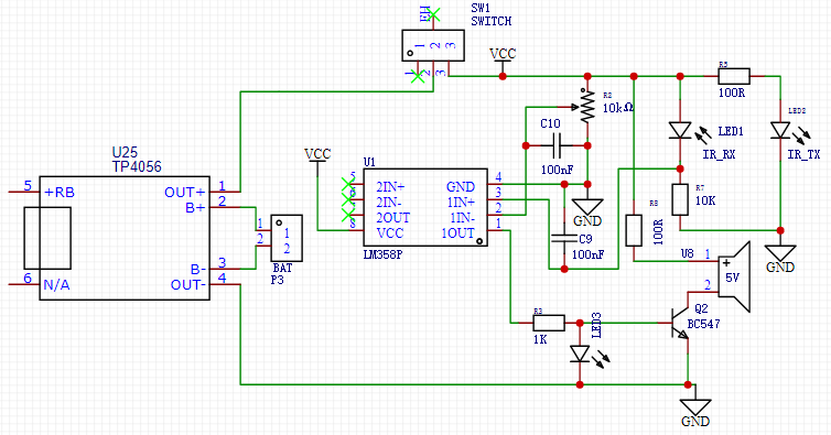
The circuit is powered by a rechargeable battery, which can be charged using a TP4056 charging module. The key components include the IR transmitter (IR_TX) and the IR receiver (IR_RX). The IR transmitter sends out infrared light, which bounces back when it hits an obstacle. The IR receiver picks up this reflected light to detect the presence of obstacles.
The heart of the circuit is the LM358 operational amplifier. It processes the signals received from the IR sensor. When the IR sensor detects an obstacle, the LM358 amplifies this signal, triggering an alert. This alert is indicated by an LED (LED3) lighting up and possibly activating a buzzer through a transistor (Q2), making it easy for visually impaired users to know when something is in their way. The circuit also features a switch (SW1) to turn the device on and off, ensuring it only operates when needed.
This simple and effective design helps visually impaired individuals navigate safely by providing timely alerts when obstacles are detected.
Working of the Smart Blind Stick Project
The Smart Blind Stick using Op-Amp circuit works by detecting obstacles and alerting the user. It starts with the IR sensor, which has two parts: the IR transmitter (IR_TX) and the IR receiver (IR_RX). The IR transmitter sends out infrared light, and when this light hits an obstacle, it bounces back to the IR receiver. This reflected light generates a signal indicating the presence of an obstacle.

This signal is then sent to the LM358 operational amplifier (Op-Amp), which is the brain of the circuit. The Op-Amp takes the small signal from the IR sensor and amplifies it. When the signal shows that an obstacle is near, the Op-Amp produces a higher output voltage. This amplified signal is used to trigger an alert system.
The alert system includes an LED and a buzzer. When the Op-Amp’s output voltage is high enough, it activates a transistor that turns on the LED and the buzzer. The LED lights up, and the buzzer sounds, warning the user of the obstacle.
This way, the circuit helps visually impaired individuals by providing a clear and immediate warning when something is in their path, making navigation safer and easier.


1 Comment
what is the value of Vcc??