Close Menu
  • Articles
    • Learn Electronics
    • Product Review
    • Tech Articles
  • Electronics Circuits
    • 555 Timer Projects
    • Op-Amp Circuits
    • Power Electronics
  • Microcontrollers
    • Arduino Projects
    • STM32 Projects
    • AMB82-Mini IoT AI Camera
    • BLE Projects
  • IoT Projects
    • ESP8266 Projects
    • ESP32 Projects
    • ESP32 MicroPython
    • ESP32-CAM Projects
    • LoRa/LoRaWAN Projects
  • Raspberry Pi
    • Raspberry Pi Projects
    • Raspberry Pi Pico Projects
    • Raspberry Pi Pico W Projects
  • Electronics Calculator
Facebook X (Twitter) Instagram
  • About Us
  • Disclaimer
  • Privacy Policy
  • Contact Us
  • Advertise With Us
Facebook X (Twitter) Instagram Pinterest YouTube LinkedIn
How To Electronics
  • Articles
    • Learn Electronics
    • Product Review
    • Tech Articles
  • Electronics Circuits
    • 555 Timer Projects
    • Op-Amp Circuits
    • Power Electronics
  • Microcontrollers
    • Arduino Projects
    • STM32 Projects
    • AMB82-Mini IoT AI Camera
    • BLE Projects
  • IoT Projects
    • ESP8266 Projects
    • ESP32 Projects
    • ESP32 MicroPython
    • ESP32-CAM Projects
    • LoRa/LoRaWAN Projects
  • Raspberry Pi
    • Raspberry Pi Projects
    • Raspberry Pi Pico Projects
    • Raspberry Pi Pico W Projects
  • Electronics Calculator
How To Electronics
Home » Inductive Water Level Indicator with Display using IC 74HC157 & CD4511
Electronics Circuits

Inductive Water Level Indicator with Display using IC 74HC157 & CD4511

Mamtaz AlamBy Mamtaz AlamUpdated:February 2, 20252 Comments2 Mins Read
Share Facebook Twitter LinkedIn Telegram Reddit WhatsApp
Inductive Water Level Indicator with Display using IC 74HC157 & CD4511
Share
Facebook Twitter LinkedIn Pinterest Email Reddit Telegram WhatsApp

Introduction:

In this post, we are going to learn how to design Inductive Water Level Indicator with a Display. Most water level indicators are based upon the number of LEDs that glow to indicate the corresponding level of water in the container. But here we have designed Numeric Water Level Indicator using IC 74HC157 & CD4511. It is a digital version of the water level indicator using a 7-segment display to show the water level in numeric form from 0 to 9.

Check some advance projects here:
1. GSM Based Water Level Monitoring System with Arduino
2. IoT Based Water Level Control & Monitoring with ESP8266
3. Monitor Water Tank Level with GSM & ESP8266 on Blynk


Components Required:

C++
1
2
3
4
5
6
7
8
9
1. 5V Power Supply
2. 74HC147 IC (equivalent IC 74LS147)
3. CD4511 IC (equivaent IC 74HC4511)
4. Common Cathode 7 Segment Display
5. Transistor BC547 - 4
6. Resistor 560K - 10
7. Resistor 12K - 4
8. Resistor 33k - 4
9. Water Container


Circuit Diagram: Inductive Water Level Indicator with Display using IC 74HC157 & CD4511

Inductive Water Level Indicator with Display using IC 74HC157 & CD4511


Circuit Explanation & Working:

The numeric water indicator circuit works off 5V regulated power supply. It is built around priority encoder IC 74HC147 & BCD-to-7-segment decoder IC CD4511 & common cathode 7-segment display.

When the water tank is empty, all the inputs of 74HC147 remain high. As a result, its output also remains high, making all the inputs of CD4511 low. Display at this stage shows ‘0,’ which means the tank is empty. Similarly, when the water level reaches L-1 position, the display shows ‘1,’ and when the water level reaches the L-8 position, the display shows ‘8.’ Finally, when the tank is full, all the inputs of 74HC147 become low and its output goes low to make all the inputs of CD4511 high. The display now shows ‘9,’ which means the tank is full.


Design Consideration:

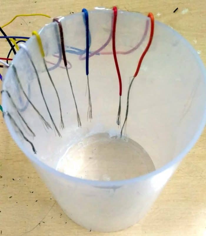
It is recommended to use stainless steel wire without any corrosion for dipping into the water, else you may not get the desired result at the display.

The container should be wired like this as shown in the figure below.

Inductive Water Level Indicator with Display using IC 74HC157 & CD4511

The result is shown when dipped into the water from number 0 to 9:

Inductive Water Level Indicator with Display using IC 74HC157 & CD4511

Share. Facebook Twitter Pinterest LinkedIn Tumblr Email Reddit Telegram WhatsApp
Previous ArticleHall Effect Sensor A3144 Magnetic Switch Basics Working & Explanation
Next Article Detailed Information about Aerospace Electronic Components

Related Posts

Water Level Alert using Float Sensor & 555 Timer

Water Level Alert using Float Sensor & 555 Timer

2K
Adjustable Auto On Off Delay Timer Circuit Using 555 IC

555 Based Adjustable Auto On Off Delay Timer Circuit

Updated:February 14, 20252K

12V DC to 220V AC Inverter Circuit & PCB

Updated:February 2, 20251461K
DIY Smart Blind Stick using Op-Amp & IR Sensor

DIY Smart Blind Stick using Op-Amp & IR Sensor

Updated:February 2, 202515K
Square Wave Generator Circuit with Op Amp IC LM358

Square Wave Generator Circuit with Op Amp IC LM358

Updated:February 2, 202513K
Gas Leak Detection & Alarm using 555 Timer IC

Gas Leak Detection & Alarm using 555 Timer IC

Updated:February 2, 202525K
View 2 Comments

2 Comments

  1. Jim on October 7, 2020 2:24 AM

    Thinking your leads to the water container are shown connected to the wrong side of the resistors in the schematic.

    Reply
  2. Rushikesh on June 3, 2022 8:45 AM

    Can you upload pcb design

    Reply

CommentsCancel reply

Latest Posts
IoT Based PM & Air Quality Monitoring System using ESP32

IoT Based PM & Air Quality Monitoring System using ESP32

May 31, 2026
DIY ESP32 MLX90640 IR Thermal Camera with Live Web Display

DIY ESP32 MLX90640 IR Thermal Camera with Live Web Display

May 10, 2026
IoT Activity Tracker with ESP32 & Accelerometer Gyroscope

IoT Activity Tracker with ESP32 & Accelerometer/Gyroscope

May 2, 2026
A Guide to Sourcing Obsolete ICs for Vintage Projects

Beyond AliExpress: A Guide to Sourcing Obsolete ICs for Vintage Projects

April 21, 2026

ESP32 IoT Vehicle Motion Analyzer with MPU6050 & LIS3MDL

April 27, 2026
Building a Smart Sensor Node with a BLE Microcontroller

Building a Smart Sensor Node with a BLE Microcontroller

February 26, 2026
High-Accuracy Pitch, Roll, Yaw with ESP32 & BNO08x IMU

High-Accuracy Pitch, Roll, Yaw with ESP32 & BNO08x IMU

April 27, 2026
DIY Colorimeter using AS7265x Spectroscopy Sensor & ESP32

DIY Colorimeter using AS7265x Spectroscopy Sensor & ESP32

February 1, 2026
Top Posts & Pages
  • Buck Converter: Basics, Working, Design & Application
    Buck Converter: Basics, Working, Design & Application
  • 12V DC to 220V AC Inverter Circuit & PCB
    12V DC to 220V AC Inverter Circuit & PCB
  • How to use INA226 DC Current Sensor with Arduino
    How to use INA226 DC Current Sensor with Arduino
  • How to use Modbus RTU with ESP32 to read Sensor Data
    How to use Modbus RTU with ESP32 to read Sensor Data
  • Designing of MPPT Solar Charge Controller using Arduino
    Designing of MPPT Solar Charge Controller using Arduino
  • ECG Graph Monitoring with AD8232 ECG Sensor & Arduino
    ECG Graph Monitoring with AD8232 ECG Sensor & Arduino
  • IoT Based ECG Monitoring with AD8232 ECG Sensor & ESP32
    IoT Based ECG Monitoring with AD8232 ECG Sensor & ESP32
  • IoT AC Energy Meter with PZEM-004T & ESP32 WebServer
    IoT AC Energy Meter with PZEM-004T & ESP32 WebServer
Categories
  • Arduino Projects (197)
  • Articles (60)
    • Learn Electronics (19)
    • Product Review (15)
    • Tech Articles (28)
  • Electronics Circuits (46)
    • 555 Timer Projects (21)
    • Op-Amp Circuits (7)
    • Power Electronics (13)
  • IoT Projects (204)
    • ESP32 MicroPython (7)
    • ESP32 Projects (81)
    • ESP32-CAM Projects (15)
    • ESP8266 Projects (76)
    • LoRa/LoRaWAN Projects (22)
  • Microcontrollers (38)
    • AMB82-Mini IoT AI Camera (4)
    • BLE Projects (18)
    • STM32 Projects (19)
  • Raspberry Pi (93)
    • Raspberry Pi Pico Projects (57)
    • Raspberry Pi Pico W Projects (12)
    • Raspberry Pi Projects (24)
Follow Us
  • Facebook
  • Twitter
  • Pinterest
  • Instagram
  • YouTube
About Us

“‘How to Electronics’ is a vibrant community for electronics enthusiasts and professionals. We deliver latest insights in areas such as Embedded Systems, Power Electronics, AI, IoT, and Robotics. Our goal is to stimulate innovation and provide practical solutions for students, organizations, and industries. Join us to transform learning into a joyful journey of discovery and innovation.

Copyright © How To Electronics. All rights reserved.
  • About Us
  • Disclaimer
  • Privacy Policy
  • Contact Us
  • Advertise With Us

Type above and press Enter to search. Press Esc to cancel.

Ad Blocker Enabled!
Ad Blocker Enabled!
Looks like you're using an ad blocker. Please allow ads on our site. We rely on advertising to help fund our site.