Close Menu
  • Articles
    • Learn Electronics
    • Product Review
    • Tech Articles
  • Electronics Circuits
    • 555 Timer Projects
    • Op-Amp Circuits
    • Power Electronics
  • Microcontrollers
    • Arduino Projects
    • STM32 Projects
    • AMB82-Mini IoT AI Camera
    • BLE Projects
  • IoT Projects
    • ESP8266 Projects
    • ESP32 Projects
    • ESP32 MicroPython
    • ESP32-CAM Projects
    • LoRa/LoRaWAN Projects
  • Raspberry Pi
    • Raspberry Pi Projects
    • Raspberry Pi Pico Projects
    • Raspberry Pi Pico W Projects
  • Electronics Calculator
Facebook X (Twitter) Instagram
  • About Us
  • Disclaimer
  • Privacy Policy
  • Contact Us
  • Advertise With Us
Facebook X (Twitter) Instagram Pinterest YouTube LinkedIn
How To Electronics
  • Articles
    • Learn Electronics
    • Product Review
    • Tech Articles
  • Electronics Circuits
    • 555 Timer Projects
    • Op-Amp Circuits
    • Power Electronics
  • Microcontrollers
    • Arduino Projects
    • STM32 Projects
    • AMB82-Mini IoT AI Camera
    • BLE Projects
  • IoT Projects
    • ESP8266 Projects
    • ESP32 Projects
    • ESP32 MicroPython
    • ESP32-CAM Projects
    • LoRa/LoRaWAN Projects
  • Raspberry Pi
    • Raspberry Pi Projects
    • Raspberry Pi Pico Projects
    • Raspberry Pi Pico W Projects
  • Electronics Calculator
How To Electronics
Home » Gas Leak Detection & Alarm using 555 Timer IC
555 Timer Projects

Gas Leak Detection & Alarm using 555 Timer IC

Mamtaz AlamBy Mamtaz AlamUpdated:February 2, 20252 Comments4 Mins Read
Share Facebook Twitter LinkedIn Telegram Reddit WhatsApp
Gas Leak Detection & Alarm using 555 Timer IC
Share
Facebook Twitter LinkedIn Pinterest Email Reddit Telegram WhatsApp

Overview

In this project, we will build a Gas Leak Detection & Alarm System using IC 555 Timer and MQ-2 Gas Sensor. It works as a Home Security Alarm during Gas Leakage. Whenever the sensor detects gas, the LED & Buzzer goes high indication the audio visual alarming.

We will use MQ-2 Gas Sensor which is one of the low cost and popular gas sensor in the market. The MQ-2 gas sensor is sensitive to LPG, i-butane, propane, methane, alcohol, Hydrogen and smoke. In the circuit, the 555 Timer IC is configured in astable mode. The output signal from this gas sensor module is used to drive a 555 timer astable multivibrator.


Components Required

Following are the components required to build a Gas Leak Detection & Alarm using 555 Timer IC.

  1. Resistors (22Ω, 4.7k Ω, 10k Ω, 1k Ω, 560 Ω)
  2. Variable Resistor 10k Ω
  3. 1N4148 Zener diode
  4. Capacitors 100nF – 2
  5. MQ-2 Gas Sensor Module
  6. 555 timer IC
  7. Transistor BC547
  8. 5V Buzzer
  9. LED 5V Red
  10. 5-9V DC Power Supply


MQ2 Gas/Smoke Sensor Module

The MQ-2 gas sensor is a versatile and cost-effective solution for detecting a variety of gases.

MQ2 Gas Sensor

The MQ-2 sensor stands out as a multifunctional gas detector that can identify various gases such as alcohol, carbon monoxide, hydrogen, isobutene, liquefied petroleum gas, methane, propane, and smoke. Its affordability and user-friendly attributes make it a favorite choice for beginners in the field.

Technical Specifications

  • Target Gases: LPG, Propane, Methane, Alcohol, Hydrogen, Smoke
  • Operating Voltage: Typically 5V (with a preheat time of over 24 hours for initial use)
  • Load Resistance: 20 KΩ
  • Heater Resistance: 33Ω ± 5%
  • Sensing Resistance: 10 KΩ – 60 KΩ
  • Heating consumption: <800mw
  • Sensitivity: High to gases in the scope of detection
  • Concentration Range: 200 – 10000ppm
  • Preheat Duration: 20 seconds (minimum)
  • Operating Temperature: -10 to 50 degrees Celsius

Circuit: Gas Leak Detection & Alarm using 555 Timer

Here is the circuit diagram for Gas Leak Detection & Alarm based on 555 Timer IC and MQ-2 Gas Sensor. In this circuit the IC 555 Timer is configured in astable multivibrator mode.

Gas Leak Detection & Alarm using 555 Timer IC

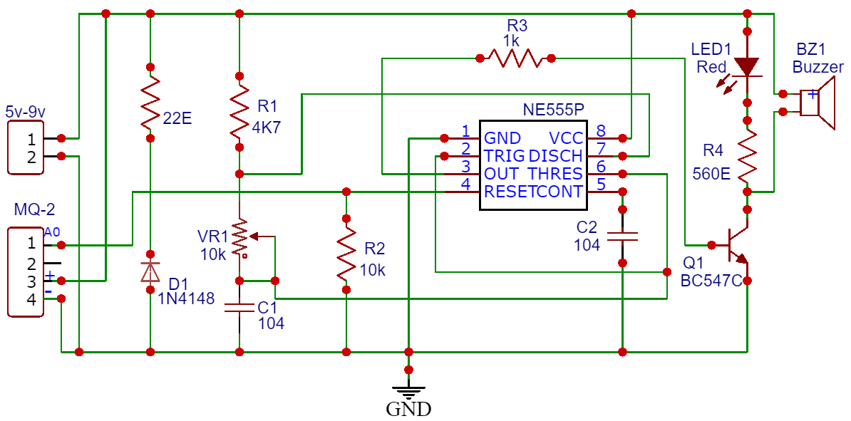
The 555 timer IC (NE555P) is the core of the alarm system. It’s connected as follows: pin 1 to GND, pin 8 to VCC, pin 4 to VCC for resetting, and pins 2, 6, and threshold (THR) through a capacitor C2 (104 or 0.1 µF). The timing components R3 (1k ohm) and C2 determine the frequency of the output oscillation on pin 3. This output drives a transistor Q1 (BC547) which in turn switches the load consisting of a red LED (LED1) and a buzzer (BZ1) in series with a resistor R4 (560 ohm) to limit the current.


The analog output of the sensor, is connected through a 22-ohm resistor to a voltage divider circuit formed by R1 (4.7K ohm) and the potentiometer VR1 (10k ohm). The sensor’s output is also connected to a diode (D1, 1N4148) for protection, and this node is tied to pin 2 (Trigger) of the 555 timer IC through capacitor C1 (0.1 µF).

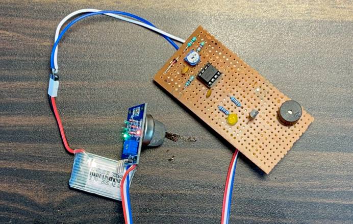
The circuit can be assembled on a Vero Board or Zero PCB. You can use a 9V Battery to Supply the power to the entire system.


Working of the Circuit

In this circuit, the purpose of the potentiometer is to set the threshold level for gas concentration. The LPG concentration of 1000 ppm (parts per million) in the area is enough to trigger the circuit. When the gas concentration exceeds this threshold, the output voltage increases to a level that triggers the 555 timer. This output drives a transistor Q1 which in turn switches the load consisting of a red LED and a buzzer.

Using Alcohol to increase the Gas Concentration

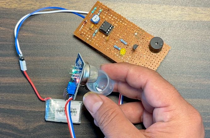
The High output causes the LED to light up and the buzzer to sound, thus signaling the presence of gas. The LED and the buzzer will continue to alert until the gas concentration drops below the set threshold, at which point the 555 timer will reset, turning off the alarm indicators.

You may checkout some Gas Level Detection related projects:

  • Gas Leak Alarm System using Arduino
  • IoT Gas Level Detection
  • Gas Leak Detection with SMS Alert
  • Gas Leak Detection with Email Alert
Share. Facebook Twitter Pinterest LinkedIn Tumblr Email Reddit Telegram WhatsApp
Previous ArticleIoT AC Energy Meter with ESP32 & HMI Display
Next Article IR Thermometer with MLX90614 & Raspberry Pi Pico

Related Posts

Water Level Alert using Float Sensor & 555 Timer

Water Level Alert using Float Sensor & 555 Timer

2K
Adjustable Auto On Off Delay Timer Circuit Using 555 IC

555 Based Adjustable Auto On Off Delay Timer Circuit

Updated:February 14, 20252K
Rainfall Detector Alarm using 555 Timer & Rain Sensor

Rainfall Detector Alarm using 555 Timer & Rain Sensor

Updated:February 2, 20254K
Dark/Light Detector using 555 Timer

Dark/Light Detector using 555 Timer & LDR – Electronics Mini Project

Updated:February 2, 202516K
Servo Motor Controller & Tester Circuit using 555 Timer IC

Servo Motor Controller & Tester Circuit using 555 Timer IC

Updated:October 8, 20234K
PWM Based DC Motor Speed Control using 555 Timer

PWM Based DC Motor Speed Control using 555 Timer

Updated:August 10, 202313K
View 2 Comments

2 Comments

  1. Alex Ribeiro on March 19, 2024 6:42 PM

    You need to develop a relay with a 9-minute timer, when activated via a button, would there be anything?

    Reply
  2. Rob M on April 24, 2024 9:37 PM

    The schematic and the description of operation do not match. The potentiometer only affects the frequency of the buzzer and the 22ohm res and diode seem to do nothing as the circuit operates without both components. The dots in the schematic should only be placed at connected junctions but I see them wherever there is a component. Seeing the diode with 22ohm resistor spanning the power rails is confusing. Following every other schematic rule, I omitted the diode and 22ohm and it made no difference.

    Reply

CommentsCancel reply

Latest Posts
IoT Based PM & Air Quality Monitoring System using ESP32

IoT Based PM & Air Quality Monitoring System using ESP32

May 31, 2026
DIY ESP32 MLX90640 IR Thermal Camera with Live Web Display

DIY ESP32 MLX90640 IR Thermal Camera with Live Web Display

May 10, 2026
IoT Activity Tracker with ESP32 & Accelerometer Gyroscope

IoT Activity Tracker with ESP32 & Accelerometer/Gyroscope

May 2, 2026
A Guide to Sourcing Obsolete ICs for Vintage Projects

Beyond AliExpress: A Guide to Sourcing Obsolete ICs for Vintage Projects

April 21, 2026

ESP32 IoT Vehicle Motion Analyzer with MPU6050 & LIS3MDL

April 27, 2026
Building a Smart Sensor Node with a BLE Microcontroller

Building a Smart Sensor Node with a BLE Microcontroller

February 26, 2026
High-Accuracy Pitch, Roll, Yaw with ESP32 & BNO08x IMU

High-Accuracy Pitch, Roll, Yaw with ESP32 & BNO08x IMU

April 27, 2026
DIY Colorimeter using AS7265x Spectroscopy Sensor & ESP32

DIY Colorimeter using AS7265x Spectroscopy Sensor & ESP32

February 1, 2026
Top Posts & Pages
  • Buck Converter: Basics, Working, Design & Application
    Buck Converter: Basics, Working, Design & Application
  • 12V DC to 220V AC Inverter Circuit & PCB
    12V DC to 220V AC Inverter Circuit & PCB
  • How to use INA226 DC Current Sensor with Arduino
    How to use INA226 DC Current Sensor with Arduino
  • How to use Modbus RTU with ESP32 to read Sensor Data
    How to use Modbus RTU with ESP32 to read Sensor Data
  • Designing of MPPT Solar Charge Controller using Arduino
    Designing of MPPT Solar Charge Controller using Arduino
  • IoT Based ECG Monitoring with AD8232 ECG Sensor & ESP32
    IoT Based ECG Monitoring with AD8232 ECG Sensor & ESP32
  • ECG Graph Monitoring with AD8232 ECG Sensor & Arduino
    ECG Graph Monitoring with AD8232 ECG Sensor & Arduino
  • IoT AC Energy Meter with PZEM-004T & ESP32 WebServer
    IoT AC Energy Meter with PZEM-004T & ESP32 WebServer
Categories
  • Arduino Projects (197)
  • Articles (60)
    • Learn Electronics (19)
    • Product Review (15)
    • Tech Articles (28)
  • Electronics Circuits (46)
    • 555 Timer Projects (21)
    • Op-Amp Circuits (7)
    • Power Electronics (13)
  • IoT Projects (204)
    • ESP32 MicroPython (7)
    • ESP32 Projects (81)
    • ESP32-CAM Projects (15)
    • ESP8266 Projects (76)
    • LoRa/LoRaWAN Projects (22)
  • Microcontrollers (38)
    • AMB82-Mini IoT AI Camera (4)
    • BLE Projects (18)
    • STM32 Projects (19)
  • Raspberry Pi (93)
    • Raspberry Pi Pico Projects (57)
    • Raspberry Pi Pico W Projects (12)
    • Raspberry Pi Projects (24)
Follow Us
  • Facebook
  • Twitter
  • Pinterest
  • Instagram
  • YouTube
About Us

“‘How to Electronics’ is a vibrant community for electronics enthusiasts and professionals. We deliver latest insights in areas such as Embedded Systems, Power Electronics, AI, IoT, and Robotics. Our goal is to stimulate innovation and provide practical solutions for students, organizations, and industries. Join us to transform learning into a joyful journey of discovery and innovation.

Copyright © How To Electronics. All rights reserved.
  • About Us
  • Disclaimer
  • Privacy Policy
  • Contact Us
  • Advertise With Us

Type above and press Enter to search. Press Esc to cancel.

Ad Blocker Enabled!
Ad Blocker Enabled!
Looks like you're using an ad blocker. Please allow ads on our site. We rely on advertising to help fund our site.