Close Menu
  • Articles
    • Learn Electronics
    • Product Review
    • Tech Articles
  • Electronics Circuits
    • 555 Timer Projects
    • Op-Amp Circuits
    • Power Electronics
  • Microcontrollers
    • Arduino Projects
    • STM32 Projects
    • AMB82-Mini IoT AI Camera
    • BLE Projects
  • IoT Projects
    • ESP8266 Projects
    • ESP32 Projects
    • ESP32 MicroPython
    • ESP32-CAM Projects
    • LoRa/LoRaWAN Projects
  • Raspberry Pi
    • Raspberry Pi Projects
    • Raspberry Pi Pico Projects
    • Raspberry Pi Pico W Projects
  • Electronics Calculator
Facebook X (Twitter) Instagram
  • About Us
  • Disclaimer
  • Privacy Policy
  • Contact Us
  • Advertise With Us
Facebook X (Twitter) Instagram Pinterest YouTube LinkedIn
How To Electronics
  • Articles
    • Learn Electronics
    • Product Review
    • Tech Articles
  • Electronics Circuits
    • 555 Timer Projects
    • Op-Amp Circuits
    • Power Electronics
  • Microcontrollers
    • Arduino Projects
    • STM32 Projects
    • AMB82-Mini IoT AI Camera
    • BLE Projects
  • IoT Projects
    • ESP8266 Projects
    • ESP32 Projects
    • ESP32 MicroPython
    • ESP32-CAM Projects
    • LoRa/LoRaWAN Projects
  • Raspberry Pi
    • Raspberry Pi Projects
    • Raspberry Pi Pico Projects
    • Raspberry Pi Pico W Projects
  • Electronics Calculator
How To Electronics
Home » 555 Based Adjustable Auto On Off Delay Timer Circuit
555 Timer Projects Electronics Circuits

555 Based Adjustable Auto On Off Delay Timer Circuit

Mamtaz AlamBy Mamtaz AlamUpdated:February 14, 20253 Mins Read
Share Facebook Twitter LinkedIn Telegram Reddit WhatsApp
Adjustable Auto On Off Delay Timer Circuit Using 555 IC
Share
Facebook Twitter LinkedIn Pinterest Email Reddit Telegram WhatsApp

Overview

In this tutorial, we will build an IC 555 Based Adjustable Auto On Off Delay Timer Circuit. It is an adjustable delay timer circuit using 555 IC that can automatically turn on/off any output after a fixed duration. Earlier we build Automatic LED Blinking Circuit as well as Flashing Police Light Effect based on same concept.

The NE555 timer IC is a versatile component widely used in pulse generation and timing applications. The Project 555 timer-based monostable circuit is designed to control a relay for a user-adjustable period. When triggered by a push button, the circuit activates a relay (and an LED indicator) for a specific duration determined by external resistors and a capacitor. This setup is ideal for applications like timed lighting, appliance control, or automation systems.


Components Required

We need following components to build this project.
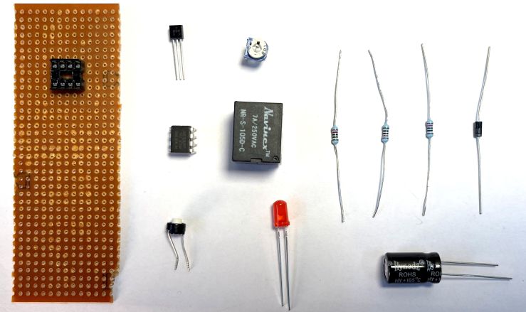
  • IC: NE555P timer IC
  • Resistors: 10K (2)
  • Resistors: 1K
  • Potentiometer: 1MΩ
  • Capacitor: 10µF
  • Diode: 1N4007
  • LED
  • Push Button Switch
  • Relay (5V/9V coil)
  • Breadboard
  • Jumper wires
  • Power supply (5V–9V)


555 Based Adjustable Auto On Off Delay Timer Circuit

The circuit is structured into four primary functional sections.

555 Based Adjustable Auto On Off Delay Timer Circuit

First, the power supply (5V–9V DC) provides the necessary voltage to the NE555P timer IC, with its ground (Pin 1) and VCC (Pin 8) connected directly to the DC source.

The timing network forms the core of the circuit, utilizing a series combination of resistor R1 (10KΩ), potentiometer VR1 (1MΩ), and capacitor C1 (10µF) to determine the output pulse duration. Pin 7 (DISCH) of the 555 IC connects to the junction between R1 and VR1, allowing the potentiometer to adjust the timing interval, while Pins 6 (THRES) and 2 (TRIG) are linked to the capacitor, enabling precise control over the charging and discharging cycles.

The trigger input consists of a push button that, when pressed, connects Pin 2 (TRIG) to the ground, initiating the timing cycle. This action transitions the 555 IC into its monostable mode.

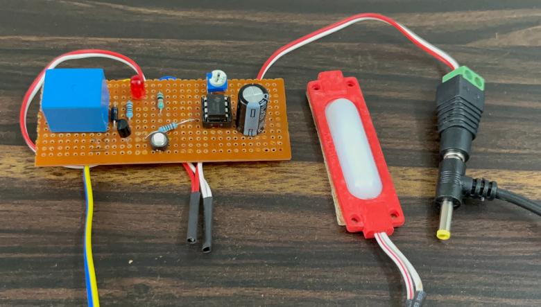
Finally, the output stage involves Pin 3 (OUT) driving a relay (U0) through resistor R3 (1KΩ), which switches connected AC/DC loads. A flyback diode (D1: 1N4007) protects the relay coil from voltage spikes, while an LED paired with a current-limiting resistor (R2: 1KΩ) provides a visual indication of relay activation.


Working and Testing

In standby mode, the 555’s output (Pin 3) is LOW. Pressing the button pulls Pin 2 (TRIG) LOW, activating the monostable mode.

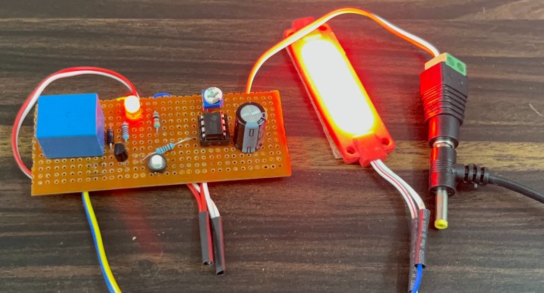
The output goes HIGH for a duration calculated as:

T = 1.1 × (R1 + VR1) × C1

Adjusting VR1 (1MΩ) varies the delay from 0.11 seconds (minimum) to 11 seconds (maximum). While HIGH, Pin 3 energizes the relay and LED. The relay switches the connected AC/DC load.
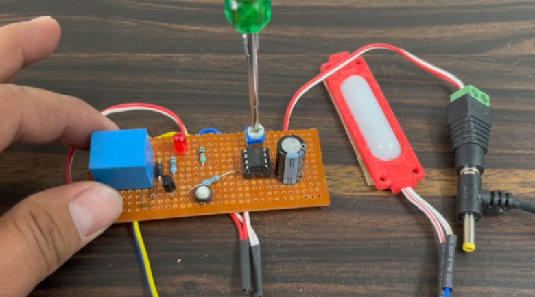


Testing Procedure:

  1. Power Up: Connect a 5V–9V supply. Ensure the LED and relay remain off initially.
  2. Trigger Test: Press the button. The LED should illuminate, and the relay should click, staying active for the set time.
  3. Adjust Timing: Rotate VR1 to test the delay range. Use a stopwatch to verify timing accuracy.
  4. Load Test: Connect a load (e.g., lamp) to the relay’s output terminals to confirm switching.

Troubleshooting Tips:

  • If the relay doesn’t activate, check R3’s value and ensure the relay coil voltage matches the supply.
  • For unstable timing, verify C1’s polarity and connections.
  • Ensure D1 is oriented correctly (cathode to +V) to suppress relay coil voltage spikes.

This is how you can make IC 555 Timer Based Adjustable Auto On Off Delay Timer Circuit for multipurpose applications.

Share. Facebook Twitter Pinterest LinkedIn Tumblr Email Reddit Telegram WhatsApp
Previous ArticleLD2410 Sensor with ESP32 – Human Presence Detection
Next Article Water Level Alert using Float Sensor & 555 Timer

Related Posts

Water Level Alert using Float Sensor & 555 Timer

Water Level Alert using Float Sensor & 555 Timer

2K

12V DC to 220V AC Inverter Circuit & PCB

Updated:February 2, 20251461K
DIY Smart Blind Stick using Op-Amp & IR Sensor

DIY Smart Blind Stick using Op-Amp & IR Sensor

Updated:February 2, 202515K
Square Wave Generator Circuit with Op Amp IC LM358

Square Wave Generator Circuit with Op Amp IC LM358

Updated:February 2, 202513K
Gas Leak Detection & Alarm using 555 Timer IC

Gas Leak Detection & Alarm using 555 Timer IC

Updated:February 2, 202525K
Inductive Water Level Indicator with Display using IC 74HC157 & CD4511

Inductive Water Level Indicator with Display using IC 74HC157 & CD4511

Updated:February 2, 202522K
Add A Comment

CommentsCancel reply

Latest Posts
IoT Based PM & Air Quality Monitoring System using ESP32

IoT Based PM & Air Quality Monitoring System using ESP32

May 31, 2026
DIY ESP32 MLX90640 IR Thermal Camera with Live Web Display

DIY ESP32 MLX90640 IR Thermal Camera with Live Web Display

May 10, 2026
IoT Activity Tracker with ESP32 & Accelerometer Gyroscope

IoT Activity Tracker with ESP32 & Accelerometer/Gyroscope

May 2, 2026
A Guide to Sourcing Obsolete ICs for Vintage Projects

Beyond AliExpress: A Guide to Sourcing Obsolete ICs for Vintage Projects

April 21, 2026

ESP32 IoT Vehicle Motion Analyzer with MPU6050 & LIS3MDL

April 27, 2026
Building a Smart Sensor Node with a BLE Microcontroller

Building a Smart Sensor Node with a BLE Microcontroller

February 26, 2026
High-Accuracy Pitch, Roll, Yaw with ESP32 & BNO08x IMU

High-Accuracy Pitch, Roll, Yaw with ESP32 & BNO08x IMU

April 27, 2026
DIY Colorimeter using AS7265x Spectroscopy Sensor & ESP32

DIY Colorimeter using AS7265x Spectroscopy Sensor & ESP32

February 1, 2026
Top Posts & Pages
  • Buck Converter: Basics, Working, Design & Application
    Buck Converter: Basics, Working, Design & Application
  • 12V DC to 220V AC Inverter Circuit & PCB
    12V DC to 220V AC Inverter Circuit & PCB
  • How to use INA226 DC Current Sensor with Arduino
    How to use INA226 DC Current Sensor with Arduino
  • How to use Modbus RTU with ESP32 to read Sensor Data
    How to use Modbus RTU with ESP32 to read Sensor Data
  • Designing of MPPT Solar Charge Controller using Arduino
    Designing of MPPT Solar Charge Controller using Arduino
  • IoT Based ECG Monitoring with AD8232 ECG Sensor & ESP32
    IoT Based ECG Monitoring with AD8232 ECG Sensor & ESP32
  • ECG Graph Monitoring with AD8232 ECG Sensor & Arduino
    ECG Graph Monitoring with AD8232 ECG Sensor & Arduino
  • IoT AC Energy Meter with PZEM-004T & ESP32 WebServer
    IoT AC Energy Meter with PZEM-004T & ESP32 WebServer
Categories
  • Arduino Projects (197)
  • Articles (60)
    • Learn Electronics (19)
    • Product Review (15)
    • Tech Articles (28)
  • Electronics Circuits (46)
    • 555 Timer Projects (21)
    • Op-Amp Circuits (7)
    • Power Electronics (13)
  • IoT Projects (204)
    • ESP32 MicroPython (7)
    • ESP32 Projects (81)
    • ESP32-CAM Projects (15)
    • ESP8266 Projects (76)
    • LoRa/LoRaWAN Projects (22)
  • Microcontrollers (38)
    • AMB82-Mini IoT AI Camera (4)
    • BLE Projects (18)
    • STM32 Projects (19)
  • Raspberry Pi (93)
    • Raspberry Pi Pico Projects (57)
    • Raspberry Pi Pico W Projects (12)
    • Raspberry Pi Projects (24)
Follow Us
  • Facebook
  • Twitter
  • Pinterest
  • Instagram
  • YouTube
About Us

“‘How to Electronics’ is a vibrant community for electronics enthusiasts and professionals. We deliver latest insights in areas such as Embedded Systems, Power Electronics, AI, IoT, and Robotics. Our goal is to stimulate innovation and provide practical solutions for students, organizations, and industries. Join us to transform learning into a joyful journey of discovery and innovation.

Copyright © How To Electronics. All rights reserved.
  • About Us
  • Disclaimer
  • Privacy Policy
  • Contact Us
  • Advertise With Us

Type above and press Enter to search. Press Esc to cancel.

Ad Blocker Enabled!
Ad Blocker Enabled!
Looks like you're using an ad blocker. Please allow ads on our site. We rely on advertising to help fund our site.