

Overview
In this project, we will build a Flashing Police Light using 555 Timer & CD4017 Decade Counter IC. The Flashing Police Lights are designed to operate at varying flash rates, typically alternating between different colors, most commonly red and blue, to grab the public’s attention and visually communicate urgency and caution.
Flashing police lights are universally recognized symbols of authority and order. When police lights flash, they signal an ongoing emergency, and everyone in the vicinity is expected to clear the path for the law enforcement vehicle. They indicate that the vehicle is responding to an emergency, and they help to alert other road users to the vehicle’s presence, often from a great distance.
Earlier we build, Heart-Shaped LED Flasher and also Automatic LED Blink project using 555 Timer IC. The current project is also based on similar conecpts.
Components Required
Following are the components that are required to make Flashing Police Light LED Effect using 555 Timer.
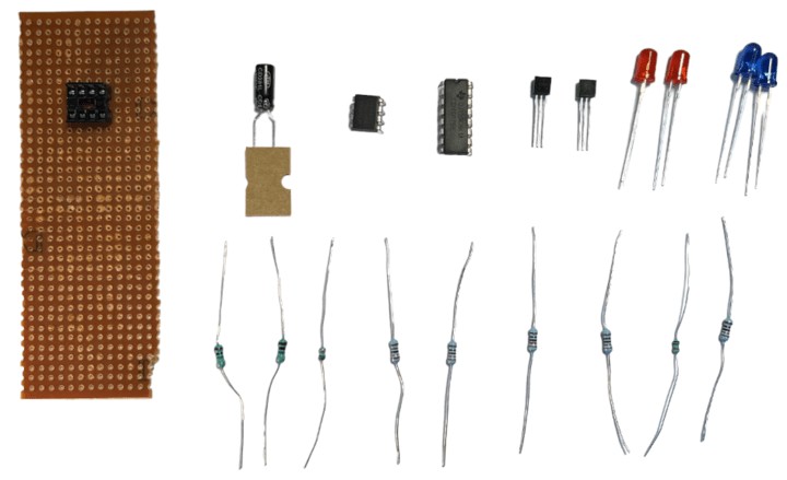
- 555 timer IC
- CD4017 Decade Counter IC
- Resistors: 10k Ohms, 1k Ohms, and 220 Ohms
- Capacitor: 10uF and 100uF
- Red and Blue LEDs (2 each)
- Transistor 2N2222 (2 each)
- Breadboard
- Connecting wires
Circuit Diagram

The above circuit is designed for police lights uses a timer that produces pulses roughly every 100 milliseconds. This translates into an ON time and an OFF time of about 50 milliseconds each. Modifying the value of the capacitor allows us to adjust these time durations.

These generated pulses are directed to a Decade Binary Counter. The counter’s role is to tally the pulses received at its clock input and, in response, raise the corresponding output pin to a high state. For instance, if the pulse count is three, the Q2 pin on the counter goes high; if it’s five, the Q4 pin goes high. Every 100 milliseconds, a peak occurs which increases the counter memory by one, adjusting the output accordingly.
Working of Flashing Police Light Project
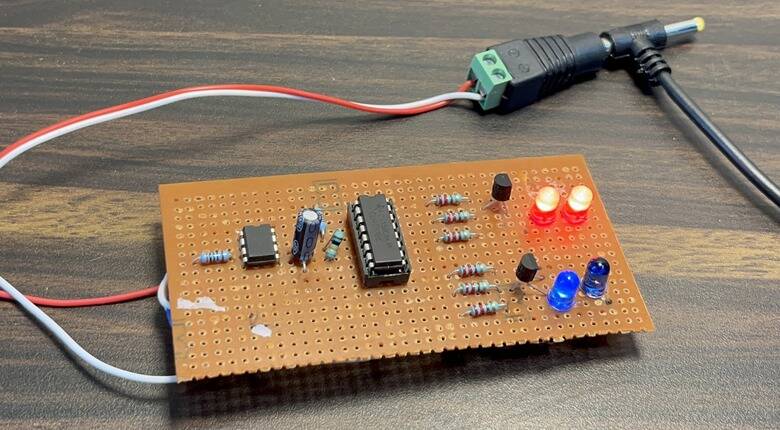
In this setup, Q0, Q2, Q4 are linked to the base of one transistor, while Q5, Q7, Q9 are linked to the base of another transistor. The first transistor controls a pair of red LEDs, while the second transistor manages a set of blue LEDs.
As previously noted, the counter’s output increases by one every 100 milliseconds until it overflows. Upon reaching this overflow, the counter resets and the count restarts from zero.
The red LED pair is controlled by Q0, Q2, Q4, and it turns on for 100ms, three times as follows:
Q0—LED is on for 100ms
Q1—LED is off for 100ms.
Q2—LED is on for 100ms
Q3—LED is off for 100ms
Q4—LED is on for 100ms
With the next clock cycle, Q5 will go high and all other outputs will go low. Q5, Q7, Q9 are configured to control the blue LED pair, causing the blue LEDs to turn on for 100ms three times, just like the red LEDs.

Therefore, we get a red LED pair that blinks three times, followed by a blue LED pair that also blinks three times. This alternating pattern between the two pairs creates the effect of police lights.


