
Overview
In this project, we will build a LoRa Based Low Power GPS Tracker using Arduino & ESP8266. This is a special kind of GPS tracker. It’s special because it uses something called LoRa, and it’s built with Arduino and ESP8266. LoRa is a technology that lets devices talk to each other over really long distances without using a lot of power.
The transmitter part of our GPS tracker is a small device made of several SMD components parts. The main parts are a microcontroller called Atmega328, a LoRa Chip named SX1276 and an L80 GPS Module. The microcontroller is like the tracker’s brain, the LoRa Chip lets it send GPS location, and the GPS module shows the location with Latitude & Longitude. To save power, the device can go to sleep mode when it’s not being used, and it can be charged through a USB cable.
![]()
We also made the receiver for this project using ESP8266 & SX1276 LoRa Module. The tracker sends the location information to a receiver that parses GPS data and the ESP8266 chip to connect to WiFi. This receiver then sends the location information to the Blynk app, which can show you where the tracker is on a Google map.
This kind of tracker could be really useful for things like finding lost pets, keeping track of valuable items, or even in scientific research to track wildlife movements.
Before moving to the project part, you may refer to some of our earlier projects:
- Real-Time GPS Tracker using ESP8266 & Blynk with Maps
- GPS+GSM Based Vehicle Tracking System using Arduino
- ESP32 GPS Tracker using L86 GPS Module & OLED
- GPS Tracker using A9G GPRS/GPS Module & Arduino
Bill of Materials
We need the following components to make this LoRa Based GPS Tracker Project.
| ID | Name | Footprint | Quantity | Manufacturer Part |
| 1 | ATMEGA328-AU MCU | TQFP-32_L7.0-W7.0-P0 | 1 | ATMEGA328-AU |
| 2 | ESP-12E WiFi MCU | WIFIM-SMD_ESP-12E | 1 | ESP-12E |
| 3 | LDO HT7333 | SOT-89-3_L4.5-W2.5-P1.50 | 2 | HT7333-7 |
| 4 | L80 GPS Module | GPSM-SMD_L80-R | 1 | |
| 5 | LoRa SX1276 (HPD13A) | HPD13A | 2 | |
| 6 | MCP73831 | SOT-23-5 | 2 | MCP73831T-2ATI/OT |
| 7 | Capacitor 10uF | C0805 | 5 | |
| 8 | Capacitor 4.7uF | C0805 | 4 | |
| 9 | Capacitor 0.1uF | C0805 | 8 | |
| 10 | Capacitor 22pF | C0805 | 2 | |
| 11 | Capacitor 470pF | C0805 | 1 | |
| 12 | Resistor 470E | R0805 | 1 | |
| 13 | Resistor 10K | R0805 | 1 | |
| 14 | Resistor 12K | R0805 | 5 | |
| 15 | Resistor 2K | R0805 | 2 | |
| 16 | Resistor 470 | R0805 | 1 | |
| 17 | Resistor 330 | R0805 | 1 | |
| 18 | Resistor 47K | R0805 | 2 | |
| 19 | Resistor 22K | R0805 | 2 | |
| 20 | LED Red | LED0805 | 2 | |
| 21 | Transistor BC847 | SOT23 | 2 | |
| 22 | Slide Switch | TOGGLE SWITCH (1P2T) SPDT | 1 | SS12D06 |
| 23 | U.FL-R-SMT | ANT-SMD_UFL-R-SMT-1 | 2 | U.FL-R-SMT-1(40) |
| 24 | Micro USBFemale | MICRO-USB-SMD_MICRO-USB-18 | 1 | U-F-M5DD-Y-L |
| 25 | Battery Connector | 2 | ||
| 26 | Male Header (PROG) | HDR-TH_6P-P2.54-V-F | ||
| 27 | Female Header (PROG) | HDR-TH_6P-P2.54-V-M-1 | 1 | Header-Male-2.54_1x6 |
| 28 | 868MHz LoRa Antenna | 2 | HEADER 1X1 | |
| 29 | Reset Switch | SWITCH SMD 3X4X2MM | 3 | Pulsador |
| 30 | 16MHz Crystal | HC49US | 1 | HC-49US 16.000MHz |
| 31 | LiPo Battery 3.7V | 1000MAh | 2 | |
| 32 | FTDI Module | 1 | ||
| 33 | Jumper Wires | 6 |
Designing of LoRa GPS Tracker Hardware
Since the project uses LoRa Technology, we decided to use low-power and the most popular LoRa chip. In Europe the supported LoRa frequency is 868MHz. In Dubai and India, the allowed LoRa frequency is 868MHz as well. But in USA & Canada, the LoRa frequency allowed is 915MHz. In Asia frequency band of 433MHz is allocated in most of countries.
As we are in Canada, so we used LoRa Module SX1276 which supports both 868 & 915MHz frequency bands.

The SX1276, manufactured by Semtech Corporation, is a long-range, low-power radio frequency integrated circuit (RFIC) utilized widely in IoT devices for LPWAN communications. It operates within the 868/915MHz frequency range, supports various modulation types including LoRa, and is notably power-efficient, which makes it a prime choice for battery-operated devices.

Similarly for GPS Part, we used GPS Module L80 from Quectel which has an embedded patch antenna and works perfectly in receiving Satellite signals. You may refer to Arduino L80 interfacing guide to learn more about this GPS Module.
The hardware part of this project involves the transmitter and the receiver. Both the transmitter part and receiver parts are powered by 3.7V Lithium-Ion Battery. To charge the Lithium-Ion Battery, we used a BMS & Battery Charging IC MCP73831 from Microchip. The entire circuit operates at 3.3V. Hence we used an LDO HT7333 from Holtek.
Transmitter Part Design & Schematic
The transmitter is portable and uses LoRa and GPS Modules for communication. Here is a complete schematic for the transmitter part.
We used ATMega328 Microcontroller with Arduino Bootloader. You may burn the bootloader on ATMega328 raw SMD Chip or directly desolder the ATMega328 chip from Arduino Nano Board.
You can plug a 5V Micro-USB Charger to USB port charge the battery. The LED1 indicates charging status. A 3.7V Lithium-ion or LiPo Battery can be connected to a Battery Connector to power the entire circuit. The SW1 is a switch to turn ON/OFF the module. The power from the battery is fed to LDO HT7333 which limits the voltage to 3.3V. The entire circuit operates at 3.3V.

To detect the battery voltage read by the microcontroller, a voltage divider network with resistors R4 and R5 has been used. The voltage is reduced to half and is fed to Analog Pin A0 of Arduino. The L80 GPS Module is a UART module, hence the Tx and Rx of L80 connect to the D2 and D3 of Arduino respectively. We can use Software Serial for the UART Communication.
Moving to the LoRa Module SX1276 uses SPI Communication protocol. The SS, RST & DIO0 of SX1276 Connects to D10, D9 & D7 of Arduino. The other SPI pins of SX1276 are connected to ATmega328 by default assignment. The LoRa Module requires an antenna. You can use any LoRa antenna with an 868MHz frequency. A UFL Connector is provided for Antenna connection or you may solder a different antenna at ANT1 point.

In order to program the ATMega328 chip, you can use the ISP pin P1. An FTDI Module or USB-to-TTL Converter can directly be connected to the header pin.
Receiver Part Design & Schematic
The receiver part of this project consists of ESP8266 raw chip and LoRa Module SX1276. The receiver receives the incoming message from the transmitter and uploads the GPS Coordinates to the Blynk App. Here is the complete schematic for the LoRa GPS Tracker Receiver.
A workable schematic of ESP8266 circuit is used here. There is no need to press the reset or boot button while uploading the code. You can connect USB-to-TTL Converter Module to PROG Pins & program the circuit. The programming process is automatic and handled by two switches (FLS and RST), two BC547 transistors (Q1 and Q2), and a few other components.

The RTS signal resets the ESP8266, while the DTR signal puts it in flash mode, with Q1 and Q2 preventing the chip’s reset when both signals are low. Upon detecting an upload command, the ESP module auto-switches to flash mode for seamless sketch uploading. In the absence of an upload command, ESP-12E/F starts in normal mode.
Check the design reference circuit here: ESP8266 Automatic Programmer Circuit
A 5V Micro-USB Charger can be inserted into the USB port to charge the battery, with LED1 displaying the charge status. Power for the entire circuit can be provided by connecting a 3.7V Lithium-ion to the Battery Connector. The SW1 acts as a module ON/OFF switch. The battery’s power is channeled to the LDO HT7333, which restricts the voltage to 3.3V, ensuring that the whole circuit operates at this voltage.
The LoRa Module SX1276 is connected to ESP8266 via SPI Pins. We used SS, RST & DIO0 pins as GPIO15, GPIO16, and GPIO4 respectively. Connect an antenna of 868MHz with better sensitivity and strength at the ANT1 terminal. You may solder a helical antenna or connect an antenna with a UFL connector.
PCB Design, Gerber Files & PCB Ordering
Both above schematics are designed using EasyEDA. You can convert the schematic to the PCB.
The PCBs have SMD components with resistors and capacitors with an SMD package of 0805. The other ICs are also in the SMD package. The front side of the transmitter and Receiver PCB looks something like below.

Similarly, the 3D view of the PCB looks like this.


The Gerber File for the PCB is given below. You can simply download the Gerber File and order the PCB from ALLPCB at 1$ only.

You can now upload the Gerber File by choosing the Quote Now option. From these options, you can choose the Material Type, Dimensions, Quantity, Thickness, Solder Mask Color, and other required parameters.

After filling in all details, select your country and shipping method. Finally, you can place the order.
PCB & Final Hardware Assembly
After ordering the PCB, it took almost 5 days and I got my PCB.

The PCB quality from ALLPCB is superb with very high quality. That is why most of people trust ALLPCB for PCB/PCBA Services.
![]()
On the Transmitter PCB, first solder all the SMD components like resistors, capacitors, transistors, LED, push buttons & micro-USB port. After soldering all these, you can solder the ATMega328 chip. I desoldered the ATMega328 chip from Arduino Nano as it already has preinstalled Bootloader. The SX1276 LoRa Module and GPS Module is soldered as well. Then solder crystal oscillator, Battery connector, switch and female Headers pins.
![]()
On the Receiver PCB, first solder all the SMD components like resistors, capacitors, transistors, LED, push buttons & micro-USB port. Be careful about the SMD LED polarity, place it in proper direction. After soldering all these, you can solder the SX1276 LoRa Module and ESP8266 raw chip. Then solder Battery connector, switch and male Headers pins.

Now connect the battery to both transmitter and reciever PCB board.
![]()
Hence the hardware for LoRa GPS Tracker using Arduino (ATMega328) and ESP8266 is ready now. You may start the programming process.
Setting Up Blynk Application
Now in order to check the GPS data wirelessly and monitor it online, we need an IoT Server with dashboard. The Blynk App is perfect for our application.
Visit blynk.cloud and create a Blynk account on the Blynk website. Or you can simply sign in using the registered Email ID.
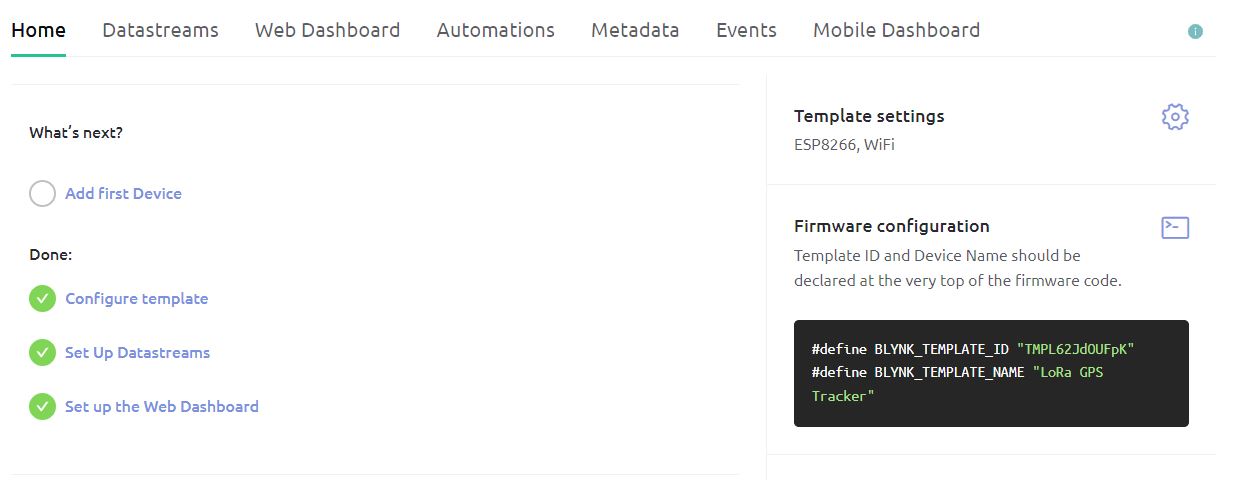
Click on +New Template.
Give any name to the Hardware such as “LoRa GPS Tracker“. Choose the Hardware type as ESP8266 and the connection type as WiFi.
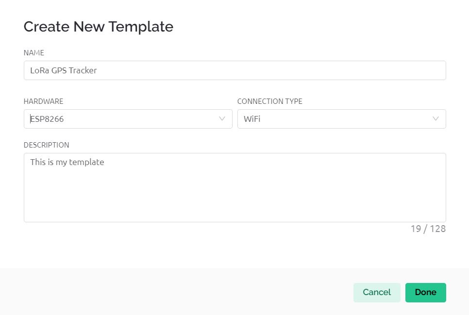
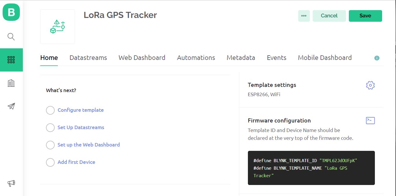
The template is created successfully.
Now we need to setup Datastreams. Therefore Click on +New Datastreams and Select Virtual Pin.
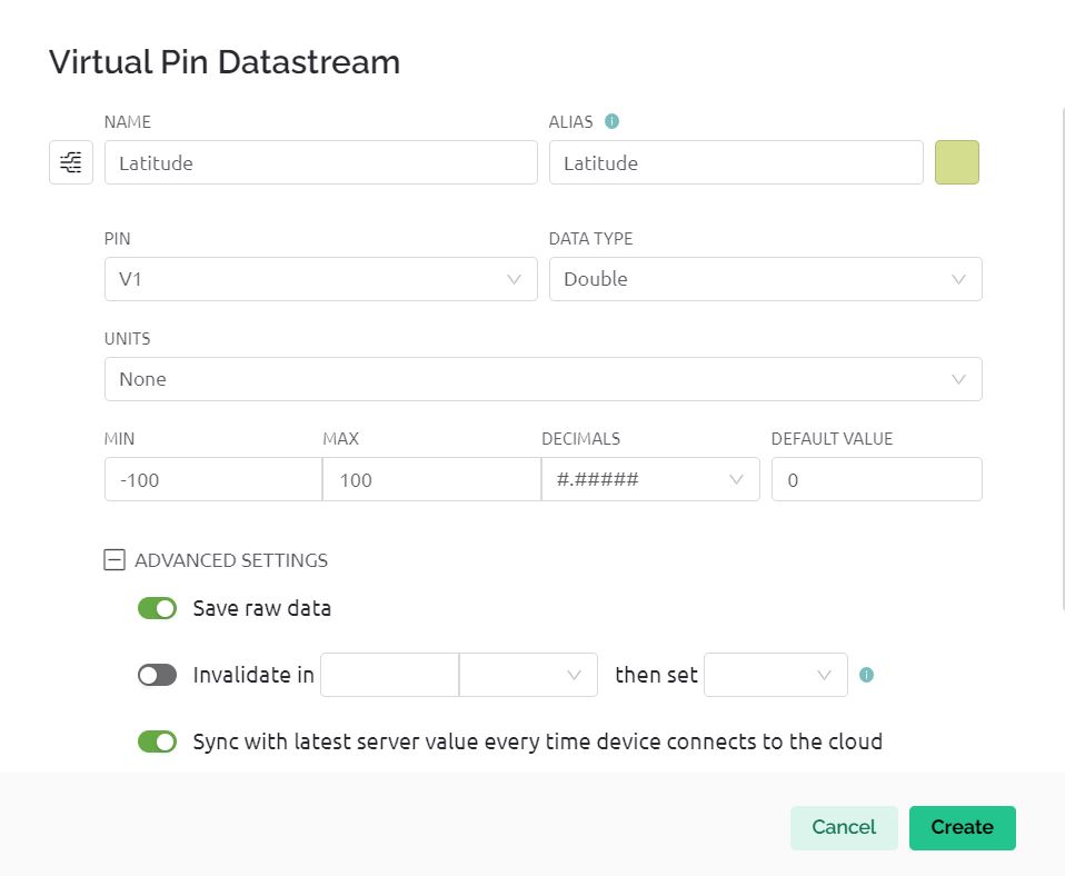
The image is of datastream for Latitude and Virtual Pin V1 is assigned.
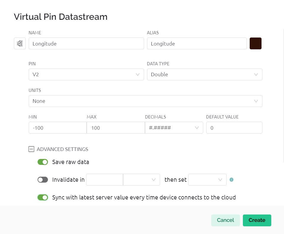
This is the datastream for Longitude and Virtual Pin V2 is assigned.
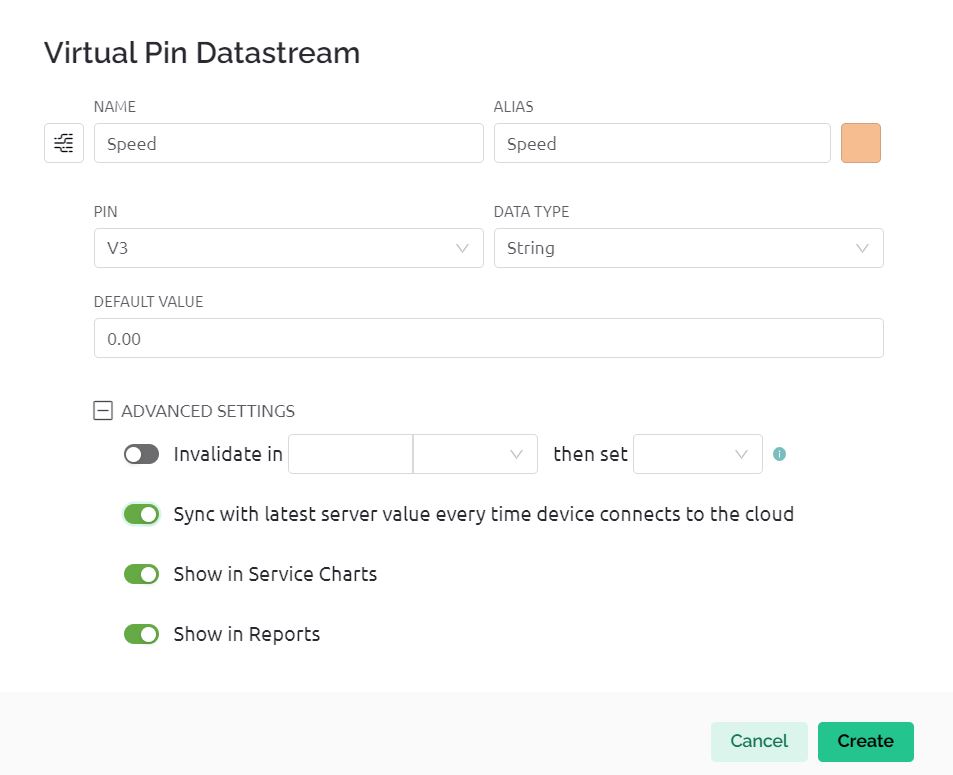
This is the datastream for Speed and Virtual Pin V3 is assigned.
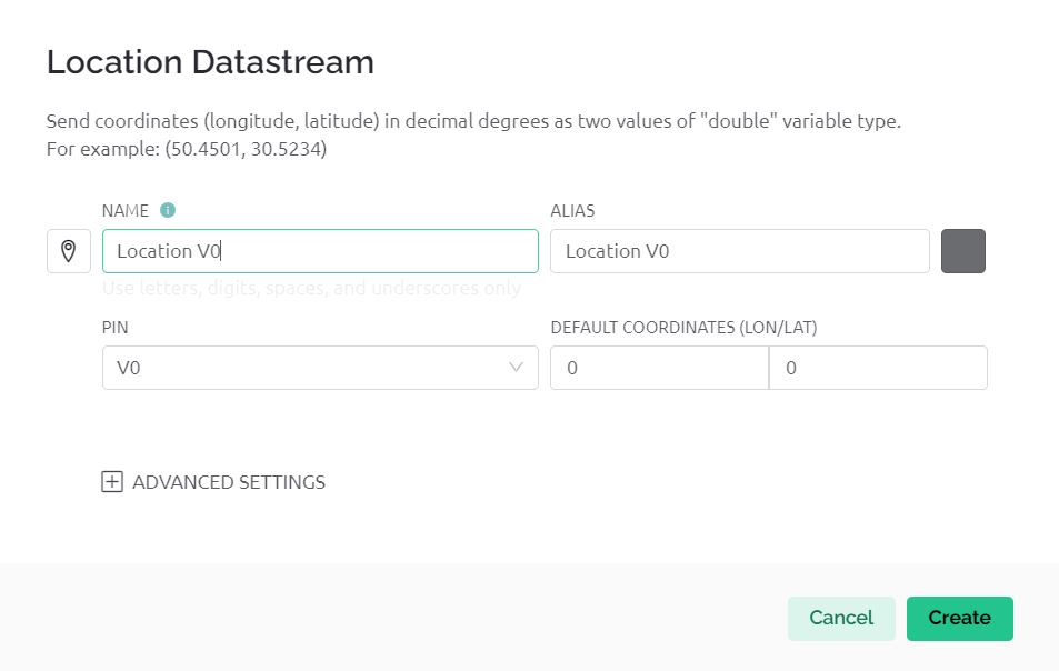
The image is for datastream for Map and Virtual Pin V0 is assigned.
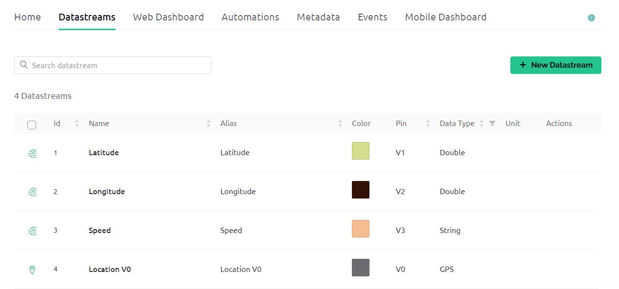
Hence Datastream part is completed.
Now go to the Web Dashboard as we need to set up the dashboard now.
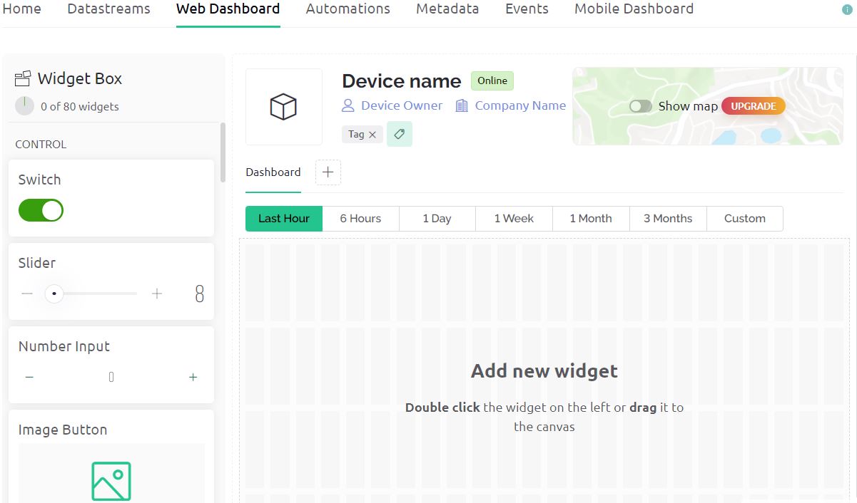
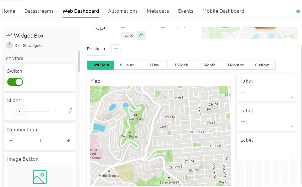
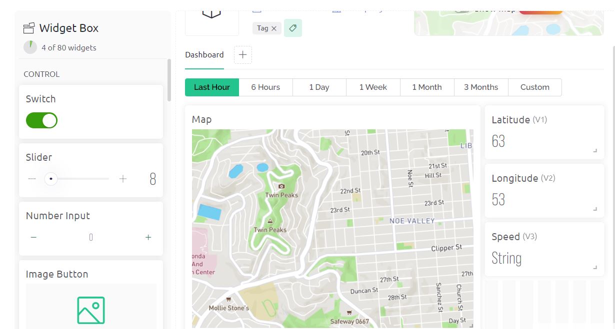
Drag and drop 4 widgets now. The Map widget is for displaying Map. The Map is a premium part. Hence you need to purchase it. Apart from the map, there are 3 other widgets for Latitude, Longitude, and Speed.
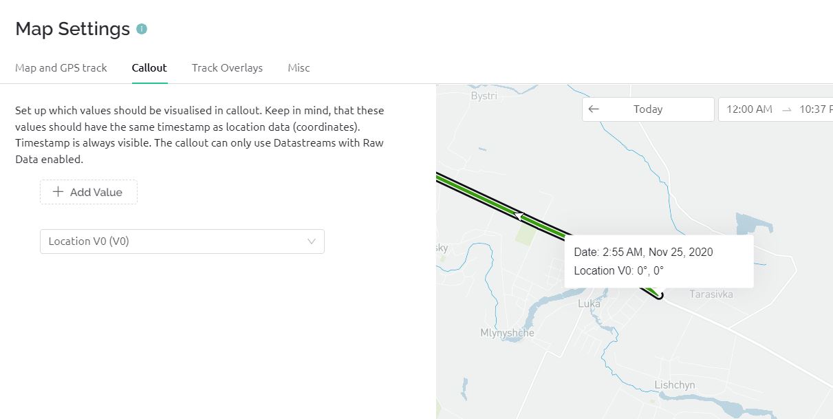
We need to set up the Map part now. For that click on settings and select the options as shown in the image below.
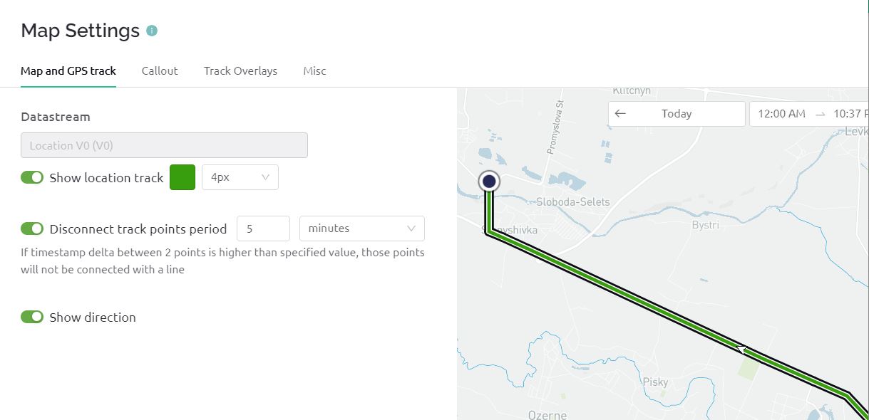
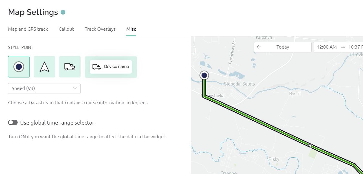
Similarly, assign the Virtual Pin V1 for Latitude, Virtual Pin V2 for Longitude, and Virtual Pin V3 for Speed.
Hence dashboard setup is complete now. Click on Save.
Now go back to Home Section and click Add First Device.
Give the device any name such as ‘LoRa GPS Tracker‘ and click on Create.
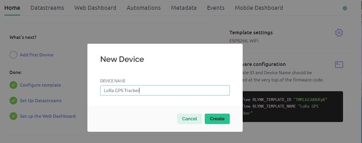
So the device has been successfully created and the authentication token is also generated.
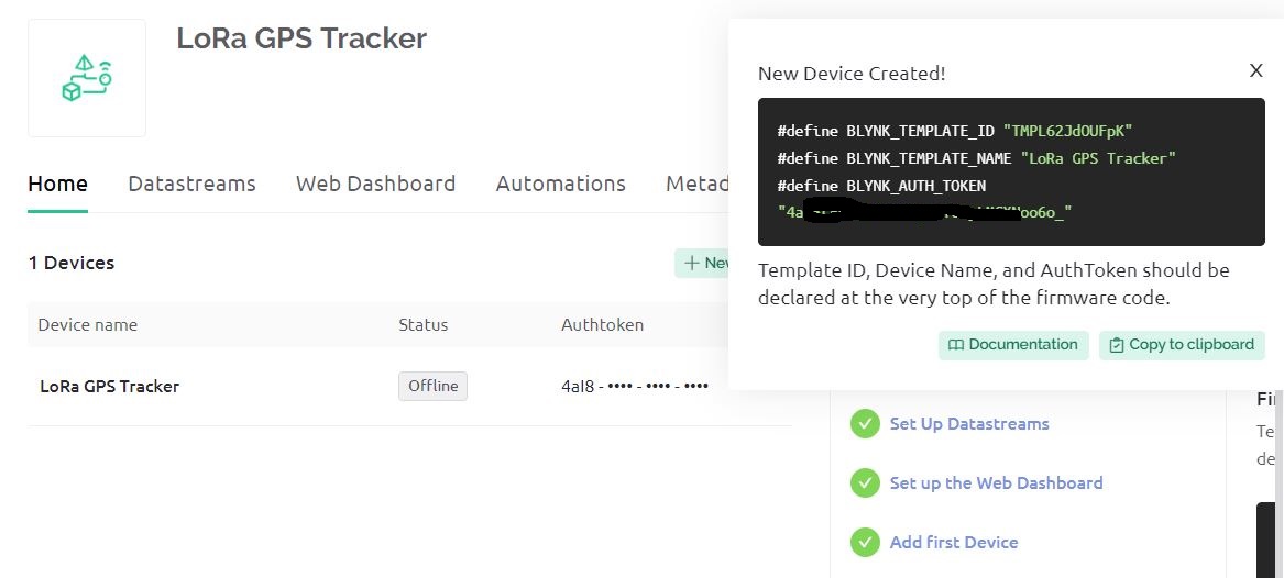
Now you can use this authentication token to connect the ESP8266 to this Blynk Dashboard.
Source Code/Program for LoRa GPS Tracker
Now let’s go through the programming part of the LoRa Based Low Power GPS Tracker with Arduino & ESP8266. Since we have transmitter and receiver circuits, therefore we need to write codes for both the transmitter and receiver circuits.
Transmitter Code
We have written the code for the Transmitter part which has an ATMega328 Microcontroller. The transmitter will acquire the data from Satellite using the L80 GPS Receiver Module. The LoRa SX1276 will transmit the data wirelessly which needs to be received and read by the receiver. The transmission is data won’t take place until the GPS receives the valid GPS coordinates. Once the GPS coordinate is received, the LoRa Data transmission start.
We have also implemented the functionality of Sleep Mode so that the device goes to sleep mode to save battery power. It will only wake up during the data transmission and again go to sleep. In this code, we put the device to sleep for 12 seconds only. You may need to modify the code to put the device to sleep mode for a longer period of time.
You may also measure the battery voltage using the ADC pin A0 assigned in the hardware part configured by a voltage divider network of 47K resistors pair. This code to measure battery voltage hasn’t been implemented in the code. You may refer to the Battery Monitoring System project to do that.
Here is the complete code for the transmitter part.
|
1 2 3 4 5 6 7 8 9 10 11 12 13 14 15 16 17 18 19 20 21 22 23 24 25 26 27 28 29 30 31 32 33 34 35 36 37 38 39 40 41 42 43 44 45 46 47 48 49 50 51 52 53 54 55 56 57 58 59 60 61 62 63 64 65 66 67 68 69 70 71 72 73 74 75 76 77 78 79 80 81 82 83 84 85 86 87 88 89 90 91 92 93 94 95 96 97 98 99 100 101 102 103 104 105 106 107 108 109 110 111 112 113 114 115 116 117 118 119 120 121 122 123 124 125 126 127 128 129 130 131 132 133 134 135 |
#include <TinyGPS++.h> #include <SoftwareSerial.h> #include <LoRa.h> #include <avr/sleep.h> #include <avr/power.h> #include <avr/wdt.h> // Define GPS serial communication pins #define rxGPS 3 #define txGPS 2 // Define LoRa parameters #define ss 10 // Pin for the CS (chip select) #define rst 9 // Pin for the RESET #define dio0 7 // Pin for the interrupt. Can be any digital pin. // Create gps and serial instance TinyGPSPlus gps; // This is the GPS object that will manage the GPS data SoftwareSerial gpsSerial(rxGPS, txGPS); // This will be the serial connection to the GPS volatile int f_wdt = 1; // This flag is used to keep track of the sleep status // Watchdog timer interrupt service routine ISR(WDT_vect) { if (f_wdt == 0) { f_wdt = 1; // If f_wdt was 0, set it to 1 } else { WDTCSR |= _BV(WDIE); // Enable the WD interrupt (note no reset) } } void setup() { Serial.begin(9600); // Begin serial communication with a baud rate of 9600 gpsSerial.begin(9600); // Begin GPS Serial with a baud rate of 9600 Serial.println("GPS initialized..."); // Initialize LoRa with specific pins and frequency LoRa.setPins(ss, rst, dio0); if (!LoRa.begin(868E6)) { // If LoRa does not start successfully, print an error message Serial.println("Starting LoRa failed!"); while (1); } Serial.println("LoRa initialized..."); // Set sleep mode to power down mode for energy efficiency set_sleep_mode(SLEEP_MODE_PWR_DOWN); } void loop() { while (gpsSerial.available()) { // Check if there is communication from GPS if (gps.encode(gpsSerial.read())) { // If GPS data can be encoded... if (gps.location.isValid()) { // ...and if the GPS data is valid // Store GPS data in strings String lat = String(gps.location.lat(), 6); String lon = String(gps.location.lng(), 6); String speed = String(gps.speed.mps()); // Print the acquired GPS data to the Serial Monitor Serial.println("GPS data acquired..."); Serial.println("LAT: " + lat); Serial.println("LONG: " + lon); Serial.println("SPEED: " + speed); // Combine GPS data into one string to send String dataToSend = "LAT:" + lat + ",LONG:" + lon + ",SPEED:" + speed; // Begin LoRa transmission LoRa.beginPacket(); LoRa.print(dataToSend); // Send the GPS data string int result = LoRa.endPacket(); // Finish LoRa transmission // Check if the LoRa transmission was successful and print result to Serial Monitor if (result) { Serial.println("Packet transmission successful"); } else { Serial.println("Packet transmission failed"); } delay(2000); // Wait 2 seconds // Go to sleep mode to save energy Serial.println("Going to sleep now"); Serial.println(); delay(100); // Sleep for 12 seconds (8 seconds + 4 seconds) f_wdt = 0; setup_watchdog(9); // Set watchdog timer for approx 8 seconds while (f_wdt == 0) { system_sleep(); } f_wdt = 0; setup_watchdog(8); // Set watchdog timer for approx 4 seconds while (f_wdt == 0) { system_sleep(); } // Disable watchdog timer wdt_disable(); delay(2000); // Wait 2 seconds } else { Serial.println("Waiting for valid GPS data..."); // If the GPS data is invalid, print an error message } } } } // Function to put the system to sleep to save energy void system_sleep() { ADCSRA &= ~(1 << ADEN); // Switch Analog to Digitalconverter OFF set_sleep_mode(SLEEP_MODE_PWR_DOWN); // Set sleep mode to power down mode sleep_enable(); // Enable sleep mode sleep_mode(); // System actually sleeps here sleep_disable(); // Disable sleep mode ADCSRA |= (1 << ADEN); // Switch Analog to Digitalconverter ON } // Function to set up watchdog timer void setup_watchdog(int i) { byte bb; int ww; if (i > 9 ) i = 9; // Ensure that the interval does not exceed the maximum bb = i & 7; if (i > 7) bb |= (1 << 5); // Set the correct bit for longer time intervals bb |= (1 << WDCE); // Enable changes ww = bb; MCUSR &= ~(1 << WDRF); // Reset the reset flag WDTCSR |= (1 << WDCE) | (1 << WDE); // Start timed sequence WDTCSR = bb; // Set new watchdog timeout value WDTCSR |= _BV(WDIE); // Enable watchdog interrupt } |
In order to upload the code to the ATMega328 chip, connect the FTDI Module to the Female header pin of the board. The FTDI Module will perfectly fit as per the hardware design.

From the board manager, Select Arduino Nano Board and COM port. Then hit the upload button to upload the code.
Receiver Code
We have written the code for the Receiver part which has an ESP8266 Chip. The Receiver circuit will receive the data from the transmitter. The received data is parsed separated to read Latitude, Longitude, and Speed. The data is then sent to the Blynk App.
From the following lines, change the WiFi SSID, Password, and Blynk Authentication Token.
|
1 2 3 |
char auth[] = "************"; // Blynk Authentication Token char ssid[] = "************"; // WiFi SSID char pass[] = "************"; // WiFi Password |
Here is the complete code for the receiver part.
|
1 2 3 4 5 6 7 8 9 10 11 12 13 14 15 16 17 18 19 20 21 22 23 24 25 26 27 28 29 30 31 32 33 34 35 36 37 38 39 40 41 42 43 44 45 46 47 48 49 50 51 52 53 54 55 56 57 58 59 60 61 62 63 64 65 66 67 68 69 70 71 72 73 74 75 76 77 |
#include <SPI.h> #include <LoRa.h> #include <ESP8266WiFi.h> #include <BlynkSimpleEsp8266.h> #define SS 15 // GPIO15 -- SX1276's CS #define RST 16 // GPIO16 -- SX1276's RESET #define DI0 4 // GPIO4 -- SX1276's IRQ(Interrupt Request) #define BLYNK_TEMPLATE_ID "TMPL6iHPnSeDn" #define BLYNK_TEMPLATE_NAME "LoRa GPS Tracker" char auth[] = "************"; // Blynk Authentication Token char ssid[] = "************"; // WiFi SSID char pass[] = "************"; // WiFi Password void setup() { Serial.begin(115200); // Start the Serial communication to send messages to the computer Blynk.begin(auth, ssid, pass); // Start Blynk delay(1000); // wait for a second // Start LoRa using the frequency appropriate for your region (eg. 868E6 for Europe, 915E6 for North America) LoRa.setPins(SS,RST,DI0); if (!LoRa.begin(868E6)) { Serial.println("Starting LoRa failed!"); while (1); } Serial.println("LoRa Receiver"); } void loop() { Blynk.run(); // Initiates Blynk // try to parse packet int packetSize = LoRa.parsePacket(); if (packetSize) { // received a packet Serial.println("Received packet:"); String incoming = ""; while (LoRa.available()) { incoming += (char)LoRa.read(); } // Parse out the latitude, longitude and speed int latIndex = incoming.indexOf("LAT:"); int lonIndex = incoming.indexOf(",LONG:"); int speedIndex = incoming.indexOf(",SPEED:"); float lat = incoming.substring(latIndex + 4, lonIndex).toFloat(); float lon = incoming.substring(lonIndex + 6, speedIndex).toFloat(); float speed = incoming.substring(speedIndex + 7).toFloat(); // Reformat the strings with specified number of digits after decimal String latString = String(lat, 6); String lonString = String(lon, 6); String speedString = String(speed, 2) + " kmph"; // Assuming speed is in meters per second Serial.print("Latitude: "); Serial.println(latString); Serial.print("Longitude: "); Serial.println(lonString); Serial.print("Speed: "); Serial.println(speedString); // print RSSI of packet Serial.print("RSSI: "); Serial.println(LoRa.packetRssi()); //Send to Blynk Blynk.virtualWrite(V1, latString.c_str()); Blynk.virtualWrite(V2, lonString.c_str()); Blynk.virtualWrite(V3, speedString.c_str()); //Send to Google Map Widget Blynk.virtualWrite(V0, (lonString+","+latString).c_str()); } } |
Connect the FTDI Module to the Male header of the receiver part using the jumper wires. Do not forget to connect the RTS Pin as well.

From the Board Manager select NodeMCU 1.0 Board and also the COM Port. Hit the upload button to upload the code.
GPS Location Tracking Testing & Demonstration
After the code is uploaded you can start testing both the transmitter and receiver device.
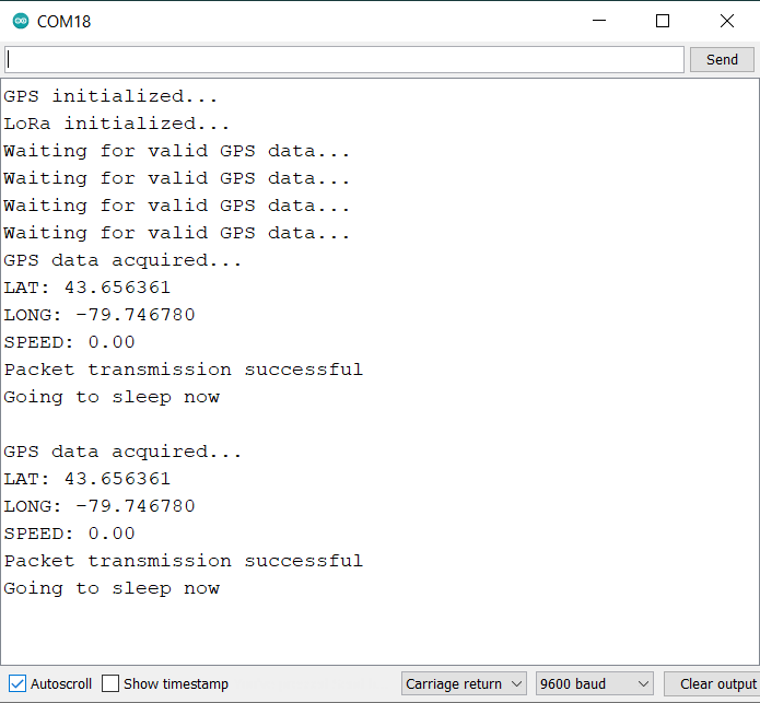
Open the Serial Monitor on the Transmitter side and you will following entries.
Once the data is sent by the transmitter, the receiver will receive the messages immediately. Open the Serial Monitor for the receiver and you will see the following entries.
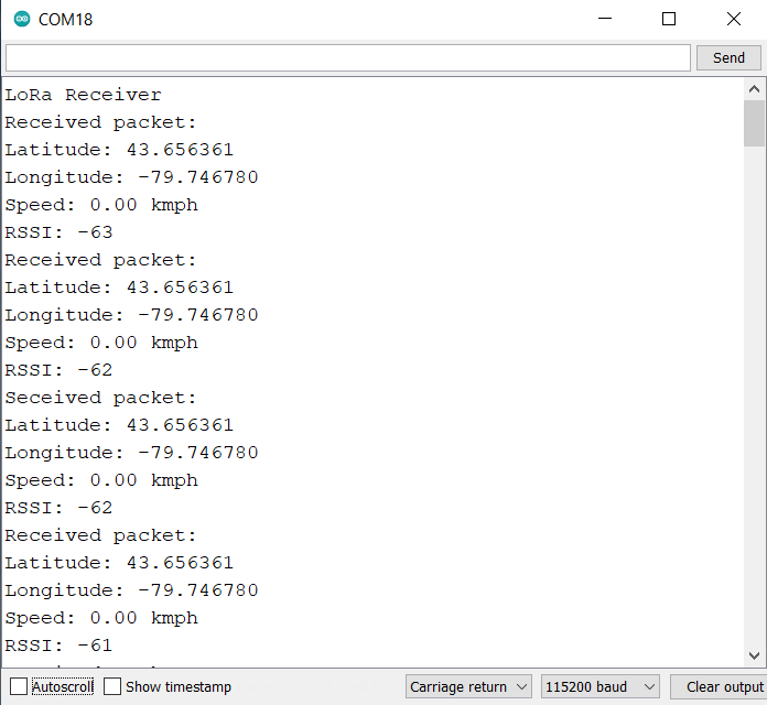
If the transmitter and receiver are communicating with each other as shown in the images above, it means the hardware is final and perfect for testing outdoors.
Now you may keep the Receiver Circuit at your home which remains connected to WiFi Network.
![]()
Meanwhile, the transmitter can be movable and taken outside for testing and ranging.
![]()
You may visit your Blynk Dashboard now. In the Blynk Dashboard, you will see the location of the transmitter.
![]()
Similarly, you can check your Mobile Dashboard as well for the GPS Location.
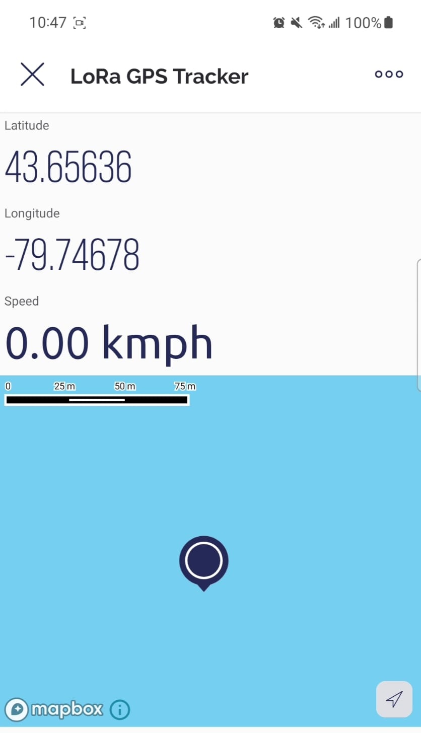
The coordinates updates automatically based on movement of the tracker. But to see in the map, you need to refresh it everytime.
Video Tutorial & Guide

Conclusion
In conclusion, this project demonstrates how a LoRa-based, low-power GPS tracker can be assembled using Arduino and ESP8266. With its unique composition involving an Atmega328 microcontroller, SX1276 LoRa Chip, and an L80 GPS Module, the tracker offers reliable and long-range communication with low power consumption. With sleep mode capabilities and USB charging, it is a highly efficient device.
Coupled with a receiver unit that connects to WiFi and sends location data to the Blynk app, this setup provides a precise and handy tool for tracking purposes. Its potential uses span from finding lost pets, safeguarding valuable possessions, to facilitating wildlife research, making it an indispensable instrument in a multitude of scenarios. The same hardware can be used to make LoRa Based Geo Fencing project for asset tracking.


2 Comments
Readymade Transmitter and receiver module available or not
The transmitter schematic and gerber file has an error. That error is causing a number of shorts:
1) short across +5v to GND on the USB connector since the VCC pin has traces to GND.
2) it causes VDD to be grounded on the MCP73831 in addition to VSS.
3) It created traces that causes C6 to be connected to two GNDs.
This image shows the junction added I assume in error that is causing the issues: http://www.redhat.systems/shorted.png
Hopefully someone can send me the schematic files, or fix that error as shown. I’ll need to re-order my boards once this is fixed. Thank you!
PS: One other issue, the bill of materials indicated the transmitter Atmel processor as a “ATMEGA328-AU”, but I could not get this to program. I however, did get ATMEGA328P-AU MPUs to program on two separate boards.