

Overview
This project is about making a DIY LoRa-Enabled IoT Geo-Fencing using GPS Module, Arduino & ESP8266. In today’s connected world, knowing an object’s location can be vital. Merging the power of LoRa technology and geo-fencing, we’ve created a powerful yet simple tracking system. Earlier we build a GPS Geo Fencing Project using ESP8266 but it has some limitations.
LoRa, known for long-distance communication with minimal power use, is our key component. Using an Arduino and the L80 GPS module, we send location data over vast distances using LoRa Communication. This data is received by the LoRa Module integrated with ESP8266, which processes it and checks if it’s within a virtual boundary, or ‘geo-fence‘, set by the user.

Our geo-fence is a virtual perimeter set on a map, like a digital fence. If our tracked item crosses this boundary, Web Dashboard displays the object is outside the boundary. The Web Dashboard is an AJAX Based Webserver which displays the Latitude, Longitude and Object Position Based on set Fence. Imagine knowing immediately if a valuable object leaves a set area or if a pet wanders too far.
This project offers a comprehensive guide on crafting the system from the ground up, covering schematics, PCB design, hardware assembly, a list of materials, source code, and testing procedures.
Bill of Materials
We need the following components to make this LoRa-Enabled IoT Geo-Fencing Project.
| ID | Name | Footprint | Quantity | Manufacturer Part |
| 1 | ATMEGA328-AU MCU | TQFP-32_L7.0-W7.0-P0 | 1 | ATMEGA328-AU |
| 2 | ESP-12E WiFi MCU | WIFIM-SMD_ESP-12E | 1 | ESP-12E |
| 3 | LDO HT7333 | SOT-89-3_L4.5-W2.5-P1.50 | 2 | HT7333-7 |
| 4 | L80 GPS Module | GPSM-SMD_L80-R | 1 | |
| 5 | LoRa SX1276 (HPD13A) | HPD13A | 2 | |
| 6 | MCP73831 | SOT-23-5 | 2 | MCP73831T-2ATI/OT |
| 7 | Capacitor 10uF | C0805 | 5 | |
| 8 | Capacitor 4.7uF | C0805 | 4 | |
| 9 | Capacitor 0.1uF | C0805 | 8 | |
| 10 | Capacitor 22pF | C0805 | 2 | |
| 11 | Capacitor 470pF | C0805 | 1 | |
| 12 | Resistor 470E | R0805 | 1 | |
| 13 | Resistor 10K | R0805 | 1 | |
| 14 | Resistor 12K | R0805 | 5 | |
| 15 | Resistor 2K | R0805 | 2 | |
| 16 | Resistor 470 | R0805 | 1 | |
| 17 | Resistor 330 | R0805 | 1 | |
| 18 | Resistor 47K | R0805 | 2 | |
| 19 | Resistor 22K | R0805 | 2 | |
| 20 | LED Red | LED0805 | 2 | |
| 21 | Transistor BC847 | SOT23 | 2 | |
| 22 | Slide Switch | TOGGLE SWITCH (1P2T) SPDT | 1 | SS12D06 |
| 23 | U.FL-R-SMT | ANT-SMD_UFL-R-SMT-1 | 2 | U.FL-R-SMT-1(40) |
| 24 | Micro USBFemale | MICRO-USB-SMD_MICRO-USB-18 | 1 | U-F-M5DD-Y-L |
| 25 | Battery Connector | 2 | ||
| 26 | Male Header (PROG) | HDR-TH_6P-P2.54-V-F | ||
| 27 | Female Header (PROG) | HDR-TH_6P-P2.54-V-M-1 | 1 | Header-Male-2.54_1x6 |
| 28 | 868MHz LoRa Antenna | 2 | HEADER 1X1 | |
| 29 | Reset Switch | SWITCH SMD 3X4X2MM | 3 | Pulsador |
| 30 | 16MHz Crystal | HC49US | 1 | HC-49US 16.000MHz |
| 31 | LiPo Battery 3.7V | 1000MAh | 2 | |
| 32 | FTDI Module | 1 | ||
| 33 | Jumper Wires | 6 |
What is Geofencing?
Geo-fencing is a location-based service in which an app or software uses GPS, Wi-Fi, cellular data, or RFID (Radio Frequency Identification) to define geographical boundaries.

It allows users or administrators to set up virtual boundaries or “fences” around a specific location. When a device enters or exits the established boundary, the geo-fencing system can trigger a response or action.
Geo-fencing has emerged as a powerful tool to define virtual boundaries and determine whether a specific point lies within these boundaries. For the task of geo-fencing, a critical consideration is to understand if the target point is inside or outside the fence. Given the fence’s potentially intricate shape, we approach this problem by envisioning the fence as an n-dimensional polygon.
The Point-in-Polygon Algorithm:
1. Assumptions:
- The user-defined fence is visualized as an n-dimensional polygon.
- The coordinates of all vertices of the polygon are available in the format Vn (xn, yn).
- The current location or tracking point is represented as T (xt, yt).

2. Working Principle: The key to this algorithm is the summation of angles between consecutive lines drawn from the tracking point to the vertices of the polygon. This total angle is what determines the point’s position relative to the fence. The angle summation can be approached either in a clockwise or anticlockwise direction.
3. Calculating the Angle: Using the dot product of two vectors (|a.b| = |a|.|b|.cos(θ)), we can derive the angle between two consecutive lines. For instance:
- Vector ‘a’ extends from the tracking point to vertex 1.
- Vector ‘b’ goes from the tracking point to vertex 2. By rearranging the equation, we can isolate ‘θ’ and compute its value.
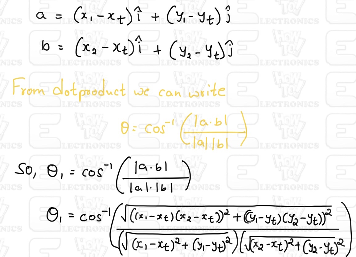
Following this method, the angles for all the vertices can be computed. If the summation of all these angles is close to 360 degrees (or 2π in radians), the point lies within the polygon. Otherwise, it lies outside.
Integration with AJAX-Based Webserver:
The efficiency and real-time nature of the Point-in-Polygon algorithm make it apt for web-based implementations. An AJAX-based webserver can be set up to constantly receive location updates of the tracking point and check its position against the geo-fence using the algorithm.
- Dynamic Updates: With AJAX, there’s no need to reload the entire web page. Only the tracking point’s data needs to be updated and processed.
- Real-time Monitoring: As the tracking point moves, the webserver can provide real-time feedback about its position relative to the fence.
- Scalability: The integration of AJAX means the server can handle multiple tracking points simultaneously, determining each one’s position relative to the fence.
Designing of IoT LoRa Based Geo Fencing Hardware
Since the project uses LoRa Technology, we decided to use low-power and the most popular LoRa chip. In Europe the supported LoRa frequency is 868MHz. In Dubai and India, the allowed LoRa frequency is 868MHz as well. But in USA & Canada, the LoRa frequency allowed is 915MHz. In Asia frequency band of 433MHz is allocated in most of countries.
As we are in Canada, so we used LoRa Module SX1276 which supports both 868 & 915MHz frequency bands.

The SX1276, manufactured by Semtech Corporation, is a long-range, low-power radio frequency integrated circuit (RFIC) utilized widely in IoT devices for LPWAN communications. It operates within the 868/915MHz frequency range, supports various modulation types including LoRa, and is notably power-efficient, which makes it a prime choice for battery-operated devices.

Similarly for GPS Part, we used GPS Module L80 from Quectel which has an embedded patch antenna and works perfectly in receiving Satellite signals. You may refer to Arduino L80 interfacing guide to learn more about this GPS Module.
The hardware part of this project involves the transmitter and the receiver. Both the transmitter part and receiver parts are powered by 3.7V Lithium-Ion Battery. To charge the Lithium-Ion Battery, we used a BMS & Battery Charging IC MCP73831 from Microchip. The entire circuit operates at 3.3V. Hence we used an LDO HT7333 from Holtek.
Transmitter Part Design & Schematic
The transmitter is portable and uses LoRa and GPS Modules for communication. Here is a complete schematic for the transmitter part.
We used ATMega328 Microcontroller with Arduino Bootloader. You may burn the bootloader on ATMega328 raw SMD Chip or directly desolder the ATMega328 chip from Arduino Nano Board.
You can plug a 5V Micro-USB Charger to USB port charge the battery. The LED1 indicates charging status. A 3.7V Lithium-ion or LiPo Battery can be connected to a Battery Connector to power the entire circuit. The SW1 is a switch to turn ON/OFF the module. The power from the battery is fed to LDO HT7333 which limits the voltage to 3.3V. The entire circuit operates at 3.3V.

To detect the battery voltage read by the microcontroller, a voltage divider network with resistors R4 and R5 has been used. The voltage is reduced to half and is fed to Analog Pin A0 of Arduino. The L80 GPS Module is a UART module, hence the Tx and Rx of L80 connect to the D2 and D3 of Arduino respectively. We can use Software Serial for the UART Communication.
Moving to the LoRa Module SX1276 uses SPI Communication protocol. The SS, RST & DIO0 of SX1276 Connects to D10, D9 & D7 of Arduino. The other SPI pins of SX1276 are connected to ATmega328 by default assignment. The LoRa Module requires an antenna. You can use any LoRa antenna with an 868MHz frequency. A UFL Connector is provided for Antenna connection or you may solder a different antenna at ANT1 point.

In order to program the ATMega328 chip, you can use the ISP pin P1. An FTDI Module or USB-to-TTL Converter can directly be connected to the header pin.
Receiver Part Design & Schematic
The receiver part of this project consists of ESP8266 raw chip and LoRa Module SX1276. The receiver receives the incoming message from the transmitter and uploads the GPS Coordinates to the Blynk App. Here is the complete schematic for the LoRa Based Geo Fencing Receiver.
A workable schematic of ESP8266 circuit is used here. There is no need to press the reset or boot button while uploading the code. You can connect USB-to-TTL Converter Module to PROG Pins & program the circuit. The programming process is automatic and handled by two switches (FLS and RST), two BC547 transistors (Q1 and Q2), and a few other components.

The RTS signal resets the ESP8266, while the DTR signal puts it in flash mode, with Q1 and Q2 preventing the chip’s reset when both signals are low. Upon detecting an upload command, the ESP module auto-switches to flash mode for seamless sketch uploading. In the absence of an upload command, ESP-12E/F starts in normal mode.
Check the design reference circuit here: ESP8266 Automatic Programmer Circuit
A 5V Micro-USB Charger can be inserted into the USB port to charge the battery, with LED1 displaying the charge status. Power for the entire circuit can be provided by connecting a 3.7V Lithium-ion to the Battery Connector. The SW1 acts as a module ON/OFF switch. The battery’s power is channeled to the LDO HT7333, which restricts the voltage to 3.3V, ensuring that the whole circuit operates at this voltage.
The LoRa Module SX1276 is connected to ESP8266 via SPI Pins. We used SS, RST & DIO0 pins as GPIO15, GPIO16, and GPIO4 respectively. Connect an antenna of 868MHz with better sensitivity and strength at the ANT1 terminal. You may solder a helical antenna or connect an antenna with a UFL connector.
PCB Design, Gerber Files & PCB Ordering
Both above schematics are designed using EasyEDA. You can convert the schematic to the PCB.
The PCBs have SMD components with resistors and capacitors with an SMD package of 0805. The other ICs are also in the SMD package. The front side of the transmitter and Receiver PCB looks something like below.

Similarly, the 3D view of the PCB looks like this.


The Gerber File for the PCB is given below. You can simply download the Gerber File and order the PCB from PCBGOGO at 1$ only.
You can use this Gerber file to order high-quality PCB for this project. To do that visit the PCBGOGO official website by clicking here: https://www.pcbgogo.com/.

You can now upload the Gerber File by choosing the Quote Now option. From these options, you can choose the Material Type, Dimensions, Quantity, Thickness, Solder Mask Color, and other required parameters.

After filling in all details, select your country and shipping method. Finally, you can place the order.
PCB & Final Hardware Assembly
After ordering the PCB, it took almost 5 days and I got my PCB.

The PCB quality from PCBGOGO is superb with very high quality. That is why most of people trust PCBGOGO for PCB/PCBA Services.
![]()
On the Transmitter PCB, first solder all the SMD components like resistors, capacitors, transistors, LED, push buttons & micro-USB port. After soldering all these, you can solder the ATMega328 chip. I desoldered the ATMega328 chip from Arduino Nano as it already has preinstalled Bootloader. The SX1276 LoRa Module and GPS Module is soldered as well. Then solder crystal oscillator, Battery connector, switch and female Headers pins.
![]()
On the Receiver PCB, first solder all the SMD components like resistors, capacitors, transistors, LED, push buttons & micro-USB port. Be careful about the SMD LED polarity, place it in proper direction. After soldering all these, you can solder the SX1276 LoRa Module and ESP8266 raw chip. Then solder Battery connector, switch and male Headers pins.

Now connect the battery to both transmitter and reciever PCB board.
![]()
Hence the hardware for IoT LoRa Based Geo Fencing using Arduino (ATMega328) and ESP8266 is ready now. You may start the programming process.
Source Code & Programming for LoRa Based Geo Fencing
Now let’s go through the programming part of the LoRa Based IoT Geo Fencing for both Arduino & ESP8266. Since we have transmitter and receiver circuits, therefore we need to write codes for both the transmitter and receiver circuits.
Before programming the device add the following libraries to the Arduino IDE:
Transmitter Code
We have written the code for the Transmitter part which has an ATMega328 Microcontroller. The transmitter will acquire the data from Satellite using the L80 GPS Receiver Module. The LoRa SX1276 will transmit the data wirelessly which needs to be received and read by the receiver. The transmission is data won’t take place until the GPS receives the valid GPS coordinates. Once the GPS coordinate is received, the LoRa Data transmission start.
You may also measure the battery voltage using the ADC pin A0 assigned in the hardware part configured by a voltage divider network of 47K resistors pair. This code to measure battery voltage hasn’t been implemented in the code. You may refer to the Battery Monitoring System project to do that.
Here is the complete code for the transmitter part.
|
1 2 3 4 5 6 7 8 9 10 11 12 13 14 15 16 17 18 19 20 21 22 23 24 25 26 27 28 29 30 31 32 33 34 35 36 37 38 39 40 41 42 43 44 45 46 47 48 49 50 51 52 53 54 55 56 57 58 59 60 61 62 63 64 65 66 67 68 69 70 71 72 73 74 75 76 77 78 79 80 81 |
#include <TinyGPS++.h> #include <SoftwareSerial.h> #include <LoRa.h> #define rxGPS 3 #define txGPS 2 #define ss 10 #define rst 9 #define dio0 7 TinyGPSPlus gps; SoftwareSerial gpsSerial(rxGPS, txGPS); //Set the closed circular or any shape boundary coordinates by clicking on multiple points (10) on google maps & copying GPS points data. const double fences[1][10][2] = {{{43.656854152544554, -79.74574573729625}, {43.6563009303527, -79.74644614831918}, {43.655571044544025, -79.74718509808494}, {43.65528281029852, -79.74688309346838}, {43.65507360724711, -79.74652326139508}, {43.65544552138444, -79.74603491403502}, {43.65606847462911, -79.74534093340348}, {43.65643573913012, -79.74510317261608}, {43.65665889291183, -79.74540517635481}, {43.65684020396768, -79.74575216819369},} }; void setup() { Serial.begin(9600); gpsSerial.begin(9600); Serial.println("GPS and LoRa Transmitter Initialized..."); LoRa.setPins(ss, rst, dio0); if (!LoRa.begin(868E6)) { Serial.println("Starting LoRa failed!"); while (1); } Serial.println("LoRa Initialized..."); } void loop() { while (gpsSerial.available()) { if (gps.encode(gpsSerial.read())) { if (gps.location.isValid()) { String lat = String(gps.location.lat(), 6); String lon = String(gps.location.lng(), 6); String dataToSend = "LAT:" + lat + ",LONG:" + lon; // Check if the current location is inside the geo-fence if (isInsideGeoFence(gps.location.lat(), gps.location.lng())) { dataToSend += ",STATUS:Inside"; } else { dataToSend += ",STATUS:Outside"; } LoRa.beginPacket(); LoRa.print(dataToSend); LoRa.endPacket(); Serial.println("Sent data: " + dataToSend); delay(2000); } } } } bool isInsideGeoFence(double latitude, double longitude) { int fenceSize = sizeof(fences[0])/sizeof(fences[0][0]); double vectors[fenceSize][2]; for(int i = 0; i < fenceSize; i++){ vectors[i][0] = fences[0][i][0] - latitude; vectors[i][1] = fences[0][i][1] - longitude; } double angle = 0; double num, den; for(int i = 0; i < fenceSize; i++){ num = (vectors[i%fenceSize][0])*(vectors[(i+1)%fenceSize][0])+ (vectors[i%fenceSize][1])*(vectors[(i+1)%fenceSize][1]); den = (sqrt(pow(vectors[i%fenceSize][0],2) + pow(vectors[i%fenceSize][1],2)))*(sqrt(pow(vectors[(i+1)%fenceSize][0],2) + pow(vectors[(i+1)%fenceSize][1],2))); angle += (180*acos(num/den)/M_PI); } return (angle > 355 && angle < 365); } |
In order to upload the code to the ATMega328 chip, connect the FTDI Module to the Female header pin of the board. The FTDI Module will perfectly fit as per the hardware design.

From the board manager, Select Arduino Nano Board and COM port. Then hit the upload button to upload the code.
Receiver Code
We have written the code for the Receiver part which has an ESP8266 Chip. The Receiver circuit will receive the data from the transmitter. The received data is parsed separated to read Latitude, Longitude, and inside/outside status. The data is visualized on an AJAX-Based WebServer.
Copy the following code to the Arduino IDE.
|
1 2 3 4 5 6 7 8 9 10 11 12 13 14 15 16 17 18 19 20 21 22 23 24 25 26 27 28 29 30 31 32 33 34 35 36 37 38 39 40 41 42 43 44 45 46 47 48 49 50 51 52 53 54 55 56 57 58 59 60 61 62 63 64 65 66 67 68 69 70 71 72 73 74 75 76 77 78 79 80 81 82 83 84 85 86 87 88 89 90 91 92 93 94 95 96 97 98 99 100 101 102 103 104 105 106 107 108 109 110 111 112 113 114 115 116 117 118 119 120 121 |
#include <ESP8266WiFi.h> #include <ESP8266WebServer.h> #include <LoRa.h> #define ss 15 #define rst 16 #define dio0 4 String receivedLat, receivedLon, receivedStatus; ESP8266WebServer server(80); void setup() { Serial.begin(115200); WiFi.softAP("LoRa_Receiver", "12345678"); Serial.println("WiFi AP Started"); Serial.println(WiFi.softAPIP()); LoRa.setPins(ss, rst, dio0); if (!LoRa.begin(868E6)) { Serial.println("Starting LoRa failed!"); while (1); } Serial.println("LoRa Initialized..."); server.on("/", HTTP_GET, handleRoot); server.on("/data", HTTP_GET, sendData); server.begin(); } void loop() { int packetSize = LoRa.parsePacket(); if (packetSize) { String receivedData = ""; while (LoRa.available()) { receivedData += (char)LoRa.read(); } Serial.println("Received: " + receivedData); parseReceivedData(receivedData); } server.handleClient(); } void parseReceivedData(String data) { int latIndex = data.indexOf("LAT:"); int lonIndex = data.indexOf(",LONG:"); int statusIndex = data.indexOf(",STATUS:"); if (latIndex != -1 && lonIndex != -1 && statusIndex != -1) { receivedLat = data.substring(latIndex + 4, lonIndex); receivedLon = data.substring(lonIndex + 6, statusIndex); receivedStatus = data.substring(statusIndex + 8); } } void handleRoot() { String html = R"html( <html> <head> <style> @import url('https://fonts.googleapis.com/css2?family=Roboto:wght@300;400;500&display=swap'); body { font-family: 'Roboto', sans-serif; text-align: center; background: linear-gradient(120deg, #d9b3ff 0%, #bababa 90%); height: 100vh; margin: 0; display: flex; flex-direction: column; align-items: center; justify-content: flex-start; // Shift content to start padding-top: 10%; // Add some top padding } h1 { color: #333; font-size: 60px; letter-spacing: 2px; margin-bottom: 30px; } .data-box { background-color: rgba(255, 255, 255, 0.9); border-radius: 30px; padding: 40px 60px; margin: 20px 0; box-shadow: 0px 20px 30px rgba(0, 0, 0, 0.05); transition: all 0.3s ease; font-size: 36px; color: #555; } .data-box:hover { transform: scale(1.05); box-shadow: 0px 25px 35px rgba(0, 0, 0, 0.1); } </style> <script> function fetchData() { fetch('/data').then(response => response.json()).then(data => { document.getElementById('latitude').innerHTML = 'Latitude: ' + data.lat; document.getElementById('longitude').innerHTML = 'Longitude: ' + data.lon; document.getElementById('status').innerHTML = 'Status: ' + data.status; }); } setInterval(fetchData, 5000); </script> </head> <body onload="fetchData()"> <h1>LoRa Geo Fencing</h1> <div class="data-box" id="latitude">Latitude: </div> <div class="data-box" id="longitude">Longitude: </div> <div class="data-box" id="status">Status: </div> </body> </html> )html"; server.send(200, "text/html", html); } void sendData() { String payload = "{\"lat\":\"" + receivedLat + "\",\"lon\":\"" + receivedLon + "\",\"status\":\"" + receivedStatus + "\"}"; server.send(200, "application/json", payload); } |
Connect the FTDI Module to the Male header of the receiver part using the jumper wires. Do not forget to connect the RTS Pin as well.

From the Board Manager select NodeMCU 1.0 Board and also the COM Port. Hit the upload button to upload the code.
Demonstration of Asset Tracking with LoRa Based Geo Fencing
After uploading the code to the both Transmitter and Receiver Side, the devices are ready for testing. Open the Serial Monitor for both devices.

The transmitter will acquire the GPS data from the satellite and display it on the Serial Monitor. It will show the status as outside or inside depending upon the location of Geo-Fencing.

On the receiver side, the data is received and displayed on the Serial Monitor. The Serial Monitor will also show the IP Address as: 192.168.4.1. This is the IP Address for Web Server. For data visualization follow the below procedure.
When the receiver is powered on, it will show the Access Point as “LoRa_Receiver“. Connect your phone or Laptop to this Access Point. The password is “12345678“.

Now go to the Web Browser of your Phone and enter the IP Address: 192.168.4.1. Then Hit Enter.

The Web Page will display the Latitude, Longitude, and GPS Tracker inside/outside position. Moreover, the data are updated dynamically after every 5 seconds without the page being refreshed.
With this test, you can confirm that the both transmitter and receiver are working fine and the IoT LoRa Based Geo Fencing Code for Arduino & ESP8266 works perfectly for asset tracking.
To test the working of the device outside, you can keep the receiver with you. Connect your phone to the Receiver Access Point. You can ask your friend to keep the transmitter with him and walk on the road.

When the transmitter is outside the defined boundary or fence, the Web Server Dashboard will display the outside status.

When the transmitter is inside the defined boundary or fence, the Web Server Dashboard will display the inside status.
For proper visualization of the Transmitter position, you can open your phone in split screen mode. The upper part of the screen should be the Web Page and the bottom part should be the Google Maps. Then you can follow your friend who is holding the transmitter.

In the above image, it is properly visualized that when the object is within the fence, the webserver dashboard shows the inside status. Similarly, when the object is outside the fence, the webserver shows outside status.
Video Tutorial & Guide

Conclusion
The DIY LoRa Enabled IoT Geo Fencing project has effectively integrated the capabilities of LoRa technology, Arduino, L80 GPS module, and ESP8266 to devise a robust tracking system that determines an object’s location and its presence within a set virtual boundary. This geo-fence, a digital perimeter marked on a map, ensures real-time monitoring and immediately alerts the user through a Web Dashboard when the tracked object goes beyond the defined limits. Whether it’s safeguarding valuables or ensuring the safety of pets, this project opens up new horizons for effective location-based monitoring in our increasingly connected world.


6 Comments
Great project but can it be used indoors in a warehouse factory for asset tracking?
This project can be used for indoor tracking. But a better technology would be the use of Ultra-Wide Band Module such as DW1000 or DW3000. I have already developed project on this.
I really liked your project and explanation. I would like to know if you have a way to get GPS (lat & long) from a cell phone and transmit the data to an Arduino Mega. I want to make a follow me robot.
Thank you in advance, Ray
Hello, I recently asked you for help in one of the projects, so I will outline the essence of the project : This is a radio beacon of not far action 1,,,1,5km : transmitter(lighthouse)-LORA-02 module+arduino nano+GPS (while the rough block diagram then it will decrease ) next receiver : LORA-02 module + ESP8266 +(android phone) . Sample video of the project! : https://how2electronics.com/lora-enabled-iot-geo-fencing-using-gps-arduino-esp8266 / (but the receiver code is not correct in the article, but it is correct in the video) So, closer to the point, almost everything worked for me, but I hit the ceiling of knowledge…I also need to additionally place a couple of buttons on the web pages that will send a call of data from the transmitter (they say that the beacon transmits coordinates not constantly but on request) and in normal mode (let’s say once every 5 seconds), this is the function I ask you to help create.What do you say to that?
What is the power consumption of the transmitter? How long can it operate with the battry?
Hi can u share me the circuit file with connect all the components maybe in Proteus file also can to my email [email protected] pls