

Overview: Geo-fence with GPS & NodeMCU ESP8266
This is a simple demo of the Geo-fence project using GPS Module & NodeMCU ESP8266. A geo-fence is a virtual border or fence that surrounds a physical site. It forms a barrier between that site and the surrounding environment like the real fence. Unlike a physical fence, Geo-Fencing with NodeMCU ESP8266 can detect movement within the virtual fence. It can be any size or shape.
Geofences are built with mapping software, which allows the user to build the geo-fence across the chosen geographic region. It is composed of a set of coordinates, such as latitude and longitude, or, in the case of a circular geofence, one point that serves as the center and radius.

In this article, we will be creating an AJAX (Asynchronous JavaScript And XML) based dynamic Web server to track the target. The virtual fence will be created by labeling the vertices of the polygon in google maps. Point in polygon algorithm will be used to determine whether the target is within the fence or outside.
Bill of Materials
In this NodeMCU Geo Fencing project, we should be going on the field for testing. Making this at the breadboard level is not a feasible idea. So, the NodeMCU should be battery-powered. I have used a LiPo single-cell battery to power the hardware. I have used TP4056 for safe charging and discharging the battery.
Below mentioned are the required materials.
| S.No. | Components | Quantity | Purchase Link |
|---|---|---|---|
| 1 | NodeMCU ESP8266 Board | 1 | Amazon | AliExpress |
| 2 | Quectel L80 GPS Module | 1 | Amazon | AliExpress |
| 3 | TP4056 Module | 1 | Amazon | AliExpress |
| 4 | 1000mAh Lip Battery | 1 | Amazon | AliExpress |
| 5 | Push Switch | 1 | Amazon | AliExpress |
| 6 | Bread board | 1 | Amazon | AliExpress |
| 7 | Jumper Wires | 1 | Amazon | AliExpress |
Point in polygon algorithm
The crucial task in Geo-fence using ESP8266 is determining whether the target is within the fence or outside. The fence could be of any shape. So we need to solve this problem by assuming that the fence is an n-dimensional polygon. Algorithm complexity also plays a crucial role in the efficiency of the tracking. Considering these concerns into account I have chosen the following algorithm for this project.
Let’s assume that the fence created by the user is an n-dimensional polygon and we have the coordinates of all the vertices of the polygon in Vn (xn, yn) format. Let the current location of the tracking point be T (xt, yt). The below animation gives you a clear picture of how this algorithm works.

The sum of angles between the consecutive lines which are drawn from the tracking point to the vertices is the deciding factor that decides whether the target is within the fence or outside the fence. The summation can be taken either clockwise or anticlockwise.
Now let’s see the steps to calculate the angle with the help of the coordinates that we have. We all knew the dot product of two vectors (|a.b| = |a|.|b|.cos(θ)). Here let ‘a‘ be the vector from the tracking point to vertex 1 and ‘b‘ be the vector from the tracking point to vertex 2. ‘θ‘ value can be found by keeping ‘θ‘ on one side of the equation and taking the remaining stuff to the other side.

In the same way, we can calculate the remaining angles.
AJAX-based Webserver
We will be creating an AJAX-based webserver to monitor the target dynamically in the realtime. So how is this AJAX-based different from the normal web servers? Let’s check out the answer to this.
In a normal web server, the client sends the request to the server then the server sends the full page as a response to the client as a response. Whenever you do any action on the current web page like submitting any text or reloading to view the updated data, the client again sends the request to the server, the server again sends the complete updated page to the client as a response.
However, with AJAX-based web servers, after the page is loaded for the first time, just the updated portion of the data will be rendered on the page without manual reloading. As a result, AJAX-based web servers suits best to monitor real-time data dynamically.
Interfacing the Quectel L80 with NodeMCU
In one of the previous articles, we have discussed how to interface the Quectel L80 GPS sensor with the Arduino Nano. The interfacing of the L80 GPS Module with NodeMCU ESP8266 is the same as before.
Follow this link to read the previous article on Interfacing the Quectel L80 with Arduino.
We will use a similar circuit to design our Geo-Fence Project with NodeMCU ESP8266.
Circuit Schematics/ Hardware
The circuit connections are straightforward. Since the Quectel L80 is UART-based, we can use software serial so that we can connect RX and TX pins of the Quectel L80 to any digital GPIOs of the Node MCU.
The battery is connected to the TP4056. Node MCU gets power from the output of the TP4056 via a switch.

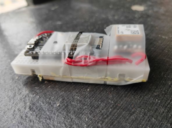
This is how the hardware looks once it has been connected. I’ve also taped the hardware to make it handy.
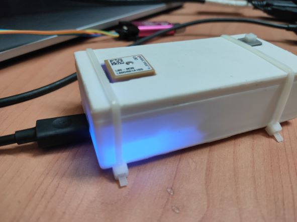
I also made a 3d printed casing. You can download the STL File and GCode File for 3D Printing.
Now everything is good from the side of the hardware. Now let’s see the software part.
Project PCB Gerber File & PCB Ordering Online
If you don’t want to assemble the circuit on a breadboard and you want PCB for the project, then here is the PCB for you. The PCB Board for Geo-Fencing Project is designed using EasyEDA online Circuit Schematics & PCB designing tool. The PCB looks something like below.

The Gerber File for the PCB is given below. You can simply download the Gerber File and order the PCB from ALLPCB at 1$ only.
You can use this Gerber file to order high quality PCB for this project. To do that visit the ALLPCB official website by clicking here: https://www.allpcb.com/.

You can now upload the Gerber File by choosing the Quote Now option. From these options, you can choose the Material Type, Dimensions, Quantity, Thickness, Solder Mask Color and other required parameters.

After filling all details, select your country and shipping method. Finally you can place the order.
Source Code/Program
Here’s the ESP8266 Geo-Fence sketch that should be uploaded to the NodeMCU ESP8266 Board.
If you are a PlatformIO type, you can clone this repository and start uploading the code to the NodeMCU by typing “pio run –target upload” in the PlatformIO CLI or by choosing the upload option. Don’t forget to star the repository after cloning :).
|
1 2 3 4 5 6 7 8 9 10 11 12 13 14 15 16 17 18 19 20 21 22 23 24 25 26 27 28 29 30 31 32 33 34 35 36 37 38 39 40 41 42 43 44 45 46 47 48 49 50 51 52 53 54 55 56 57 58 59 60 61 62 63 64 65 66 67 68 69 70 71 72 73 74 75 76 77 78 79 80 81 82 83 84 85 86 87 88 89 90 91 92 93 94 95 96 97 98 99 100 101 102 103 104 105 106 107 108 109 110 111 112 113 114 115 116 117 118 119 120 121 122 123 124 125 126 127 128 129 130 131 132 133 134 135 136 137 138 139 140 141 142 143 144 145 146 147 148 149 150 151 152 153 154 155 156 157 158 159 160 161 162 163 164 165 166 167 168 169 170 171 172 173 174 175 176 177 178 179 180 181 182 183 184 185 186 187 188 189 190 191 192 193 194 195 196 197 198 199 200 201 202 203 204 205 206 207 208 |
#include <TinyGPS++.h> #include <SoftwareSerial.h> #include <ESP8266WiFi.h> #include <WiFiClient.h> #include <ESP8266WebServer.h> #include "index.h" #define M_PI 3.14159265358979323846264338327950288 #define rxGPS 5 #define txGPS 16 const double fences[1][10][2] = {{{17.529188, 78.361845}, {17.529840, 78.361919}, {17.529934, 78.362197}, {17.530624, 78.362507}, {17.530832, 78.363043}, {17.530999, 78.363451}, {17.530924, 78.363976}, {17.529248, 78.363288}, {17.529101, 78.362858}, {17.529040, 78.362489},} }; /*Variables to store AP credentials*/ String ssid = ""; String password = ""; int WiFiConnectMode = 1; /* 0: smart config; 1: hard code*/ double latitude, longitude; int sat; String date; char lati[12]; char longi[12]; int targetStatus; int fence; char cumulativeAngle[12]; int deviceStatus = 0; SoftwareSerial gpsSerial(rxGPS, txGPS); TinyGPSPlus gps; ESP8266WebServer gpsServer(80); void connectWifi(); void updateLatLon(); void pip(); void handleRoot(); void fenceSelect(); void gps_data(); void setup(){ Serial.begin(9600); gpsSerial.begin(9600); connectWifi(); gpsServer.on("/", handleRoot); gpsServer.on("/status", fenceSelect); gpsServer.on("/values", gps_data); gpsServer.begin(); } void loop(){ while (gpsSerial.available()){ deviceStatus = 1; updateLatLon(); pip(); gpsServer.handleClient(); } gpsServer.handleClient(); } void connectWifi(){ if(WiFiConnectMode == 0){ // Operate the ESP12E in wifi station mode for smart config WiFi.mode(WIFI_STA); // Begin the smart configuration to get the Access Point credentials WiFi.beginSmartConfig(); Serial.println("------------------------------------------------"); Serial.print("Waiting for SmartConfig "); while (!WiFi.smartConfigDone()) { delay(250); Serial.print("."); } Serial.println(); Serial.println("SmartConfig done."); // Print the AP credentials to the serial monitor ssid = WiFi.SSID(); password = WiFi.psk(); Serial.println("------------------------------------------------"); Serial.print("Acesspoint SSID : "); Serial.println(ssid); Serial.print("Acesspoint password : "); Serial.println(password); Serial.println("------------------------------------------------"); // Connect the ESP12E to the AP Serial.print("Connecting to Access Point "); while (WiFi.status() != WL_CONNECTED) { delay(100); Serial.print("."); } Serial.println(); Serial.println("Connected."); Serial.println("------------------------------------------------"); Serial.print("IP Address: "); Serial.println(WiFi.localIP()); Serial.println("------------------------------------------------"); } else{ String ssid = "vikas_phone"; String password = "addepalliVikas"; WiFi.begin(ssid,password); Serial.println("------------------------------------------------"); Serial.print("Connecting to Access Point "); while (WiFi.status() != WL_CONNECTED) { delay(500); Serial.print("."); } Serial.println(""); Serial.print("Connected to "); Serial.println(ssid); Serial.print("IP address: "); Serial.println(WiFi.localIP()); Serial.println("------------------------------------------------"); } } void updateLatLon(){ Serial.print(gpsSerial.read()); Serial.print(" "); Serial.println(gps.encode(gpsSerial.read())); if (gps.encode(gpsSerial.read())) { //Serial.println("FunCheck2"); sat = gps.satellites.value(); latitude = gps.location.lat(); longitude = gps.location.lng(); dtostrf(latitude,9,7,lati); dtostrf(longitude,9,7,longi); Serial.print("SATS: "); Serial.println(sat); Serial.print("LAT: "); Serial.println(latitude,6); Serial.print("LONG: "); Serial.println(longitude,6); Serial.print("ALT: "); Serial.println(gps.altitude.meters()); Serial.print("SPEED: "); Serial.println(gps.speed.mps()); Serial.print("Date: "); date = String(gps.date.day())+"/"+gps.date.month()+"/"+gps.date.year(); Serial.println(date); Serial.print("Hour: "); Serial.print(gps.time.hour()); Serial.print(":"); Serial.print(gps.time.minute()); Serial.print(":"); Serial.println(gps.time.second()); Serial.println("---------------------------"); Serial.println("FunCheck3"); } } void pip(){ int fenceSize = sizeof(fences[fence - 1])/sizeof(fences[fence - 1][0]); double vectors[fenceSize][2]; for(int i = 0; i < fenceSize; i++){ vectors[i][0] = fences[fence - 1][i][0] - latitude; vectors[i][1] = fences[fence - 1][i][1] - longitude; } double angle = 0; double num, den; for(int i = 0; i < fenceSize; i++){ num = (vectors[i%fenceSize][0])*(vectors[(i+1)%fenceSize][0])+ (vectors[i%fenceSize][1])*(vectors[(i+1)%fenceSize][1]); den = (sqrt(pow(vectors[i%fenceSize][0],2) + pow(vectors[i%fenceSize][1],2)))*(sqrt(pow(vectors[(i+1)%fenceSize][0],2) + pow(vectors[(i+1)%fenceSize][1],2))); angle = angle + (180*acos(num/den)/M_PI); } dtostrf(angle,9,7,cumulativeAngle); if(angle > 355 && angle < 365) targetStatus = 1; else targetStatus = 0; } void handleRoot(){ String s = webpage; gpsServer.send(200, "text/html", s); } void fenceSelect(){ fence = gpsServer.arg("fenceValue").toInt(); gpsServer.send(200, "text/plane", String(fence)); } void gps_data(){ String payload = String(sat) + "#" + date + "#" + lati + "#" + longi; if(targetStatus == 0) payload = payload + "#outside"; else payload = payload + "#inside"; payload = payload + "#" + cumulativeAngle; if(deviceStatus == 0) payload = payload + "#offline"; else payload = payload + "#online"; gpsServer.send(200, "text/plane", payload); } |
The AJAX-based web server is contained in this header file. If you’re using the Arduino IDE, ensure sure this header file and the “.ino” files are both in the same directory. If you’re using PlatformIO, simply clone the above-mentioned repository.
|
1 2 3 4 5 6 7 8 9 10 11 12 13 14 15 16 17 18 19 20 21 22 23 24 25 26 27 28 29 30 31 32 33 34 35 36 37 38 39 40 41 42 43 44 45 46 47 48 49 50 51 52 53 54 55 56 57 58 59 60 61 62 63 64 65 66 67 68 69 70 71 72 73 74 75 76 77 78 79 80 81 82 83 84 85 86 87 88 89 90 91 92 93 94 95 96 97 98 99 100 101 102 103 104 105 106 107 108 109 110 111 112 113 114 115 116 117 118 119 120 121 122 123 124 125 126 127 128 129 130 131 |
const char webpage[] PROGMEM = R"=====( <!DOCTYPE html> <html> <style type="text/css"> body { background-image: url('https://images.unsplash.com/photo-1488866022504-f2584929ca5f?auto=format&fit=crop&w=1486&q=80&ixid=dW5zcGxhc2guY29tOzs7Ozs%3D'); background-size: cover; margin: 0; background-repeat: no-repeat; background-position: 0 0; transition: 2s cubic-bezier(0.645, 0.045, 0.355, 1); color :white; } hr { visibility: visible; border: 0; height: 1px; background-image: linear-gradient(to right, rgba(255, 255, 255, 0), rgba(255, 255, 255, 0.75), rgba(255, 255, 255, 0)); } .button { background-color: rgba(55, 72, 87, 0.8); border: none; color: white; padding: 12px 20px; text-align: center; text-decoration: none; display: inline-block; border-radius: 12px; font-size: 16px; } </style> <body style="background-color: #ffffff ; font-family:verdana"> <center> <p>Device Status <span id = "Device_status" style="color : rgba(0, 255, 106, 0.857);">offline</span></p> <hr style = "width: 70%;"> <h1>Dashboard</h1> <hr style = "width: 70%;"> <div> <button class="button" onclick="send(1)">Fence 1</button> <button class="button" onclick="send(2)">Fence 2</button> <p>Selected Fence: <span id="fence_id">0</span><br></p> </div> <hr style = "width: 40%;"> <div style="background-color: rgba(89, 154, 211, 0.3);; width: 30%; border-radius: 12px;"> <table style="text-align: center; " > <tr> <th style="padding: 0 20px 0 20px;">Date</th> <th style="padding: 0 20px 0 20px;">No.of Sats</th> </tr> <tr> <td><span id="date">0</span><br></td> <td><span id="sats">0</span><br></td> </tr> </table> </div> <hr style = "width: 40%;"> <div> <div style="background-color: rgba(89, 154, 211, 0.3); display: inline-block; width: 10%; border-radius: 12px;"> <table style="text-align: center; " > <tr> <th>Latitude</th> </tr> <tr> <td><span id="lat_val">0</span><br></td> </tr> <tr> <th>Longitude</th> </tr> <tr> <td><span id="lon_val">0</span><br></td> </tr> </table> </div> <div style="background-color: rgba(89, 154, 211, 0.3); display: inline-block; width: 15%; border-radius: 12px;"> <table style="text-align: center; " > <tr> <th>Target Status</th> </tr> <tr> <td><span id="target_status">0</span><br></td> </tr> <tr> <th>Cumulative Angle</th> </tr> <tr> <td><span id="angle">0</span><br></td> </tr> </table> </div> </div> <hr style = "width: 70%;"> <script> function send(fence_val) { var xhttp = new XMLHttpRequest(); xhttp.onreadystatechange = function() { if (this.readyState == 4 && this.status == 200) { document.getElementById("fence_id").innerHTML = this.responseText; } }; xhttp.open("GET", "status?fenceValue="+fence_val, true); xhttp.send(); } setInterval(function() {getData();}, 2000); function getData() { var xhttp = new XMLHttpRequest(); xhttp.onreadystatechange = function() { if (this.readyState == 4 && this.status == 200) { const data = this.responseText.split("#"); document.getElementById("date").innerHTML = data[1]; document.getElementById("sats").innerHTML = data[0]; document.getElementById("lat_val").innerHTML = data[2]; document.getElementById("lon_val").innerHTML = data[3]; document.getElementById("target_status").innerHTML = data[4]; document.getElementById("angle").innerHTML = data[5]; document.getElementById("Device_status").innerHTML = data[6]; } }; xhttp.open("GET", "values", true); xhttp.send(); } </script> </center> </body> </html> )====="; |
Code explanation
I have used the TinyGPS++ library to decode the NMEA statements that are read from the Quectel L80. The SoftwareSerial library to create a virtual serial port. The ESP8266WebServer library is used to create the AJAX-based web server.
The “connectWifi()” function makes the NodeMCU connect to the home access point (AP). The “WiFiConnectionMode” variable decides the mode of connecting to the AP. If the variable is set to “0” the device connects to the AP via smart config and if the variable is set to the “1” the device connects to the AP using the AP credentials that are hardcoded the variables “ssid“, “password” inside the function. You can use the “EspTouch” app that is available in the google play store if you choose to use the NodeMCU in soft config mode.
The “updateLatLon()” function updates the latitude, longitude, altitude, speed, and date variables whenever the function is called.
The “pip()” function updates the “targetStatus” variable whenever it is called. It implements the point-in-polygon algorithm using the updated coordinates. If the target is within the fence the “targetStatus” variable is set to “1”, “0” otherwise.
The “handleRoot()“, “fenceSelect()” and “gps_data()” are the handlers. These handles are mended to send their respective data to the client-side when it is requested. The “handlerRoot()” is defined to handle the root webpage and send the entire webpage. The “gps_data()” is defined to handle the GPS data, this handler stringifies the latitude, longitude, no. of satellites, date, target status, and cumulative angle (θsum) variables into a “#” separated string. The “fenceSelect()” handler receives the selected Geo-fence information from the webServer.
Creating fence in Google maps & hardcoding the coordinates
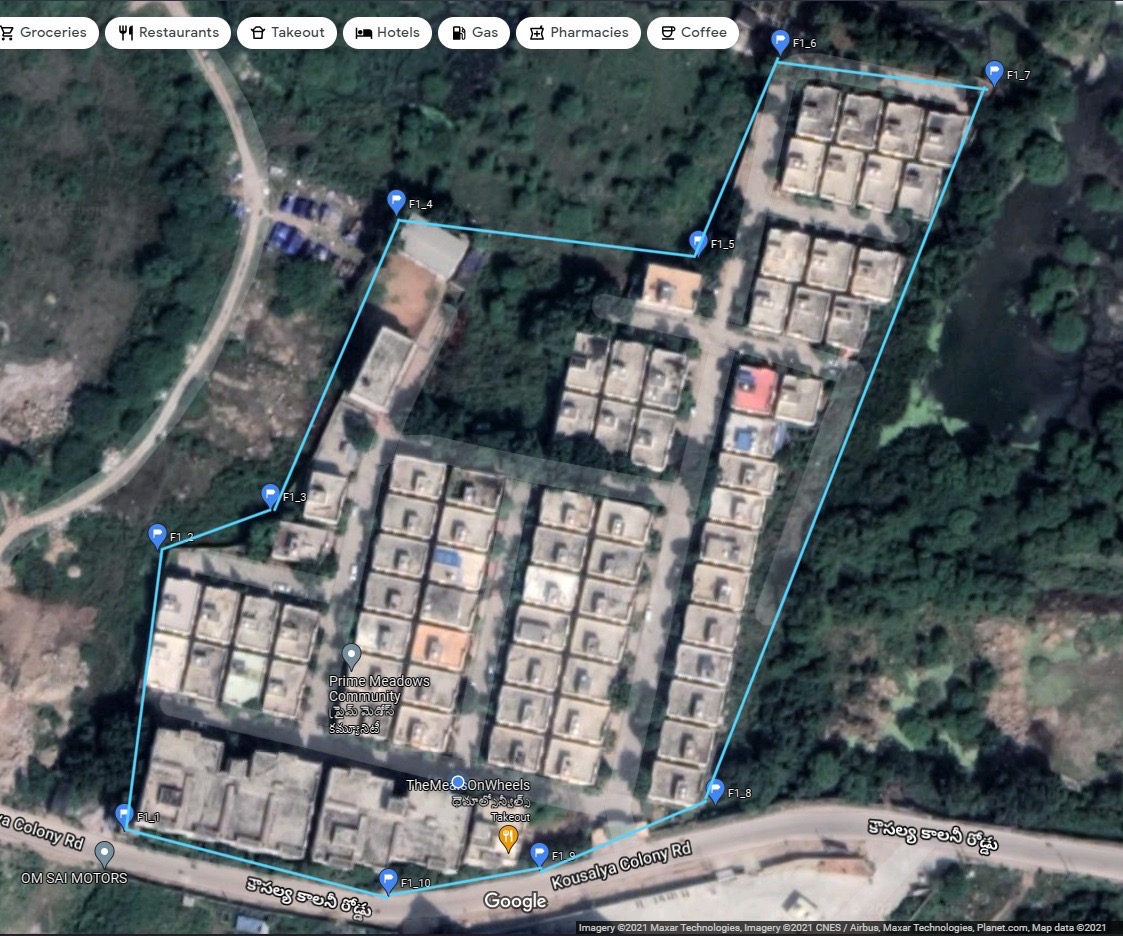
Open google maps, pin the location that you are planning to make the vertex of the fence and label the vertex and make note of the coordinates. Repeat the procedure for the remaining points too. The following is the fence that I have created and used in this project.
Now hardcode the latitude and longitudes of the fence to the variable fence, which is a three-dimensional array. The third dimension is to store the coordinates of different Geo-fence.
Test & Results of ESP8266 Geo-Fence
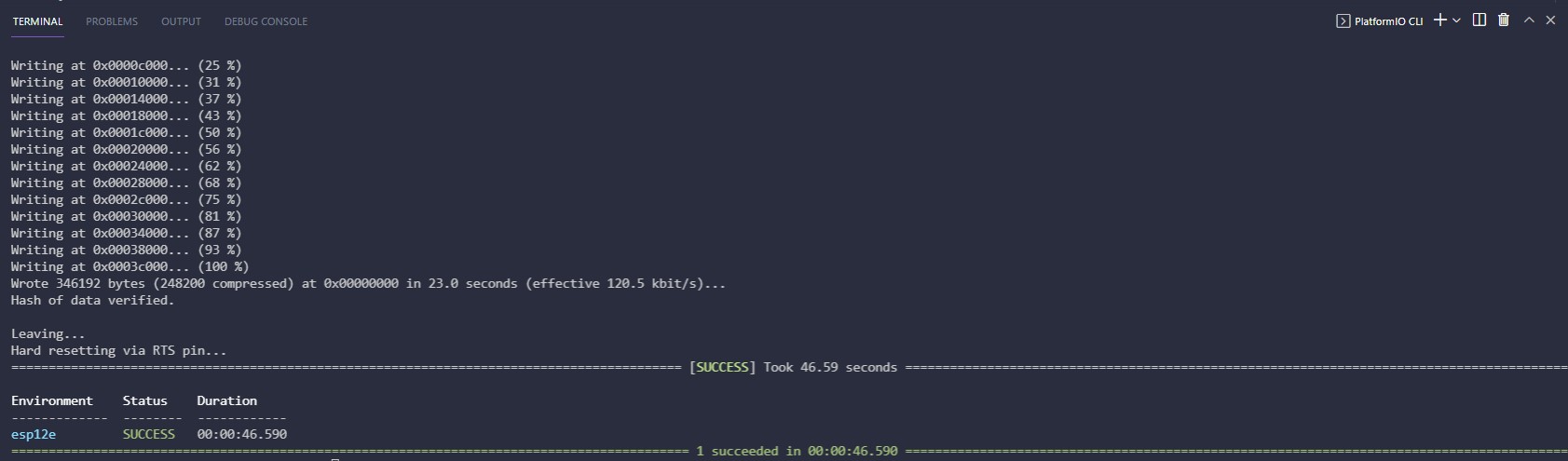
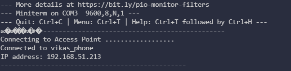
Upload the code by selecting proper settings in the IDE that you are using (either Arduino or PlatformIO). If you are using PlatformIO, after uploading the code you will be seen something like below on the PlatformIO CLI.
After this open the serial monitor. You will be seeing something like below
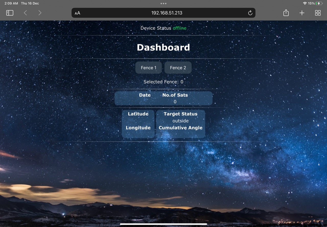
Open that IP address in the Browser. Now you can find the webserver with empty values like below
Open the google maps and the web server in split-screen mode to view the movement of the target along with the Geo-fence and also its status in the dashboard. The below gif shows the final result.

In the above gif, the Geo-fence is clearly visible. When the tacking point crosses the Geo-fence the target status variable in the dashboard updates to the value “outside” and vice versa. And also the other data like latitude, longitude, no. of connected satellites, and date can also be seen on the dashboard.
This is how we create Geo-fence or Geo Fencing with NodeMCU ESP8266 Board. A wireless version of Geo Fecing project can be made using the LoRa Module. You can check the project LoRa Based Geo Fencing for more information.
Video Tutorial & Guide


13 Comments
Can we use this module with raspberry pi
yes
Which GPS module can be used instead of the Quectel L80?
Neo 6m
That’s great news. Which sections of the code will need to be changed to be able to use that NEO 6m board?
Same word works for all the gps module. No need to change any part of the code
can we use any other server for storing the location data ?
If Yes, kindly say what part of the code needs to be changed
Can we use another webserver page for storing location?
If yes, Can you pinpoint what exactly in the code needs to be edited?
hello sir , i am expecting your reply earnestly. The gps data are not displayed at the serial monitor and also there is no update in server what should i do ?
what is M_PI ?
how to pin the points and select the area such that it surrounds only 360 degree
Can I use an arduino and without using the Web server? I will be just looking to create a geo fence to contain a smart lawnmower? Just want it contained don’t need to watch in real time?
You can’t use arduino here.