

Overview
In this tutorial, we will interface the Atlas Scientific Ph Sensor with Arduino UNO Board in both UART & I2C Mode. The Atlas Scientific EZO Ph circuit gives engineers the ability to read pH with the same accuracy & capabilities that were traditionally only found in expensive bench-top meters. The Atlast Ph Sensor Kit comes with Ph Probe, EZO Circuit Board, Signal Connector Board, Calibration Solution & Buffer Storage Solution.
Earlier I made a detailed tutorial on two different types of Ph Sensor, one was the DfRobot Ph Sensor and the other Graylogix Ph Sensor. Compared to these analog Ph sensors, the Atlas Scientific Ph Sensor is one of the most scientific and accurate Ph Sensor. It has both UART as well as I2C Interface.
In this post, we will cover the following topic about Atlas Scientific Ph Sensor Kit.
- Basic Introduction and details of Ph Electrode & signal connectors board
- Learning about the EZO Ph Circuit
- Checking the Buffer solution in which Ph Electrode is placed
- Learn about different solutions used for Ph Sensor calibration
- Interface the Atlas Ph sensor with Arduino in both UART & I2C Mode
- Learn about the method to switch from UART interface to I2C interface or Vice-Versa
- Ph Sensor Calibration method using Ph Calibration Solution
- Using the EZO I2C Ph Library
- Designing portable Ph Meter using OLED Display
- Test Sensor performance using some liquids like water, milk, or any standard solution
Bill of Materials
| S.N. | Components Name | Quantity | Purchase Links |
|---|---|---|---|
| 1 | Arduino Nano Board | 1 | Amazon | AliExpress |
| 2 | Atlas Scientific Ph Sensor Kit | 1 | Atlas Scientific |
| 3 | 0.96" I2C OLED Display | 1 | Amazon | AliExpress |
| 4 | Connecting Wires | 10 | Amazon | AliExpress |
| 5 | Breadboard | 1 | Amazon | AliExpress |
Atlas Scientific Ph Sensor Kit
Now let’s see the Ph Sensor Kit. The Atlas Scientific Ph Sensor Kit is the industrial-grade Ph Sensor for Liquid Ph Measurement. This is currently the best Ph Sensor available on market.

The complete kit contains:
1. Double junction silver/silver chloride Lab Grade pH Probe
2. Electrically Isolated EZO Carrier Board
3. EZO pH Circuit
4. 125 ml calibration solutions (pH 4, pH 7 & pH 10)
5. 125 ml pH storage solution
1. Atlas Ph Probe
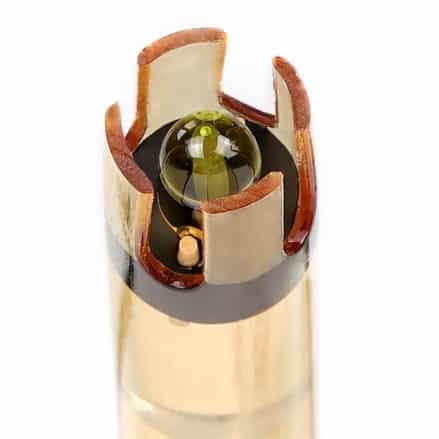
This is a Ph Sensor probe with a gold-plated BNC Connector at the end. This pH Probe features quality construction and a rugged epoxy design, making it suitable for repeated use in lab and field environments.

The sensor comes with an end tip kept in a buffer solution. For using this sensor you have to remove the soaker bottle filled with buffer solution. When you remove the cap, you can see the electrode. The bulb can handle low ionic and ultra-pure water readings including high pH solutions and also the samples containing heavy metals.
This electrode is based on the Potentiometric Ph measurement principle. The construction diagram of this probe is shown below. It is constructed with Silver wire & Silver Chloride solution are filled in it. This combination will read the Ph value in voltage.
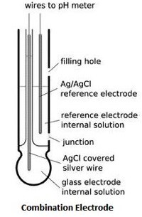
The ph probe is a Double Junction Silver/ Silver Chloride pH Probe type. The measuring range is between 0 − 14 with a maximum resolution of +/- 0.001. The probe can withstand the maximum pressure of 100 PSI & works between the temperature Range between -5 to 99°C.
When the sensor is not in use, dip this sensor in buffer solution. Do not keep this tip exposed to air. The soaker bottle is used to prevent the bulb from drying out.
2. Electrically Isolated EZO Carrier Board
The Electrically isolated EZO carrier board is an efficient way to connect Atlas Scientific circuit to the controller. It eliminates the need for a breadboard and external isolator. This carrier board utilizes the newest isolation technology, giving us the ability to put isolation into smaller footprint circuits. The five pins on top are left open for you to decide how to connect it to your system.

It accepts the input data in form of a UART or I2C interface. It operates between 3.0V − 5.0V with a typical current consumption of 28mA at 5v & 22mA at 3.3V. During power saving or sleep mode, the current consumption is 2.6mA.
3. EZO pH Circuit
This board is also the part of signal connector board. It is called the EZO Ph circuit. The EZO pH Circuit can work with any off-the-shelf pH probe, sensor & electrode. This device reads pH from a pH probe, sensor & electrode. This is insulated from all sides with epoxy resin.

This board has an LED that indicates the communication protocol type. The EZO circuit board can directly be fitted on an Isolated Carrier Board. The Ph probe also needs to be connected to the Signal Carrier board using the BNC Connector.

The following are the features specifications and data protocol related to the EZO Ph Circuit Board.
- Full range pH reading from .001 to 14.000
- Accurate pH readings down to the thousandths place (+/- 0.02)
- Temperature-dependent or temperature-independent readings
- Flexible calibration protocol supports single point, 2 points, or 3 point calibration
- Calibration required only once per year with Atlas Scientific pH probe
- Single reading or continuous reading modes
- The data format is ASCII
- UART asynchronous serial connectivity (RX/TX voltage swing 0-VCC)
- I2C (default I2C address 0x63)
- Compatible with any microprocessor that supports UART, or I2C protocol
- Operating voltage: 3.3V to 5V
- Works with any off-the-shelf pH probe
- Sleep Mode Power Consumption 0.995mA at 3.3V
4. calibration solutions (pH 4, pH 7 & pH 10)
We also get Ph sensor calibration solution with the packet. This contains two pouches of calibration solution with each of them value as Ph 4, Ph 7 & Ph 10.

At the back of the packet, there is an instruction to use the solution.
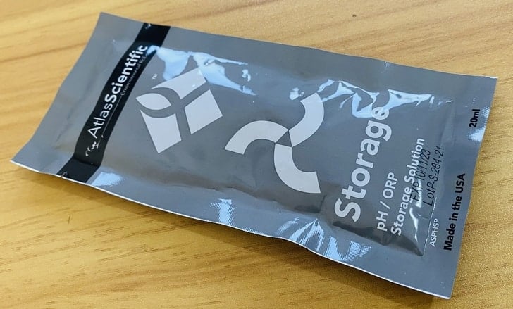
5. pH storage Buffer solution
This is the storage solution commonly known as a Buffer Solution. This solution is used to store the Ph sensor tip and prevent the bulb from drying while not in use.
Interfacing Atlas Ph Sensor with Arduino
Let us interface Atlas Scientific Ph Sensor with Arduino UNO Board. You can interface the sensor either in UART Mode or in I2C Mode.
But the question is how will you identify whether the sensor is in UART or I2C Mode. So there is a color indication LED on the EZO Ph Circuit. If the LED color is green or teal it’s in UART Mode. In case, the LED color is blue, the sensor will be in I2C Mode.

UART Mode Connection
You can interface the Atlas Ph sensor with Arduino in UART Mode using the following connection.

Connect the VCC & GND of the sensor to Arduino 3.3V & GND Pin. The UART Pin of Ph Sensor Board, i.e. Tx & Rx can be connected to any pin which supports software serial. In my case, I connected the Tx & Rx of the sensor to Arduino digital pin 3 & 2 respectively.

I2C Mode Connection
You can interface the Atlas Ph sensor with Arduino in I2C Mode using the following connection.

Connect the VCC & GND of the sensor to Arduino 3.3V & GND Pin. Connect the SDA & SCL pin of the sensor to Arduino A4 & A5 pin respectively.

Testing UART Code & Switching from UART-to-I2C Mode
If the LED color is green or teal it’s in UART Mode. By default, the sensor is in UART Mode. Connect the Tx and Rx pin of the sensor to Pin 2 & Pin 3 of Arduino and connect the power pins to 3.3V.
Here is the Atlas Ph Sensor Arduino Code for UART communication.
|
1 2 3 4 5 6 7 8 9 10 11 12 13 14 15 16 17 18 19 20 21 22 23 24 25 26 27 28 29 30 31 32 33 34 35 36 37 38 39 40 41 42 43 44 45 46 47 48 49 50 51 52 53 54 55 |
#include <SoftwareSerial.h> //we have to include the SoftwareSerial library, or else we can't use it #define rx 2 //define what pin rx is going to be #define tx 3 //define what pin tx is going to be SoftwareSerial myserial(rx, tx); //define how the soft serial port is going to work String inputstring = ""; //a string to hold incoming data from the PC String sensorstring = ""; //a string to hold the data from the Atlas Scientific product boolean input_string_complete = false; //have we received all the data from the PC boolean sensor_string_complete = false; //have we received all the data from the Atlas Scientific product float pH; //used to hold a floating-point number that is the pH void setup() { Serial.begin(9600); //set baud rate for the hardware serial port_0 to 9600 myserial.begin(9600); //set baud rate for the software serial port to 9600 inputstring.reserve(10); //set aside some bytes for receiving data from the PC sensorstring.reserve(30); //set aside some bytes for receiving data from Atlas Scientific product } void serialEvent() { inputstring = Serial.readStringUntil(13); //read the string until we see a <CR> input_string_complete = true; //set the flag used to tell if we have received a completed string from the PC } void loop() { if (input_string_complete == true) //if a string from the PC has been received in its entirety { myserial.print(inputstring); //send that string to the Atlas Scientific product myserial.print('\r'); //add a <CR> to the end of the string inputstring = ""; //clear the string input_string_complete = false; //reset the flag used to tell if we have received a completed string from the PC } if (myserial.available() > 0) //if we see that the Atlas Scientific product has sent a character { char inchar = (char)myserial.read(); //get the char we just received sensorstring += inchar; //add the char to the var called sensorstring if (inchar == '\r') //if the incoming character is a <CR> { sensor_string_complete = true; //set the flag } } if (sensor_string_complete == true) //if a string from the Atlas Scientific product has been received in its entirety { Serial.println(sensorstring); //send that string to the PC's serial monitor sensorstring = ""; //clear the string sensor_string_complete = false; //reset the flag used to tell if we have received a completed string from the Atlas Scientific product } } |
From these tools menu, select Arduino UNO Board and the COM port to which your board is connected. Then hit the upload button to upload the code.
After uploading the code, open the serial monitor and select the baud rate at 9600 and enable the Carriage return option. The Serial Monitor will start displaying the Ph Value
Type I and click on send. I mean information. So, an OK message will appear.
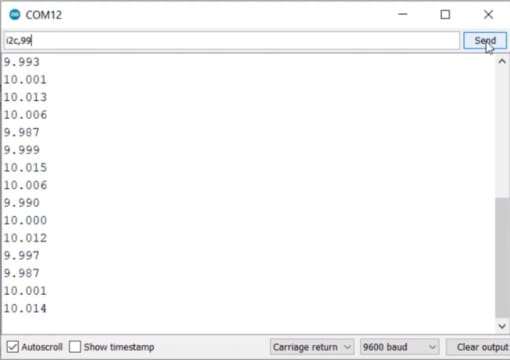
The default I2C address of the sensor is 99 or 0x63. Now to change to I2C Mode, type “I2C,99” or anything between 0 to 127. Then click on send. Now sensor is changed to I2C Mode & the LED color will change to Blue.
Testing I2C Code & Switching from I2C-to-UART Mode
If the LED color is blue then the Ph Sensor is in I2C Mode. So remove the Tx, Rx wires and connect SDA & SCL Pin of the sensor to A4 & A5 of Arduino Board. Also connect the power pins to 3.3V.
Here is the Atlas Ph Sensor Arduino Code for I2C communication.
|
1 2 3 4 5 6 7 8 9 10 11 12 13 14 15 16 17 18 19 20 21 22 23 24 25 26 27 28 29 30 31 32 33 34 35 36 37 38 39 40 41 42 43 44 45 46 47 48 49 50 51 52 53 54 55 56 57 58 59 60 61 62 63 64 65 66 67 68 69 70 71 72 73 74 75 76 77 78 79 80 81 82 83 84 85 86 87 88 89 90 91 |
#include <Wire.h> //enable I2C. #define address 99 //default I2C ID number for EZO pH Circuit is 99 char computerdata[20]; //we make a 20 byte character array to hold incoming data from a pc/mac/other. byte received_from_computer = 0; //we need to know how many characters have been received. byte serial_event = 0; //a flag to signal when data has been received from the pc/mac/other. byte code = 0; //used to hold the I2C response code. char ph_data[20]; //we make a 20 byte character array to hold incoming data from the pH circuit. byte in_char = 0; //used as a 1 byte buffer to store inbound bytes from the pH Circuit. byte i = 0; //counter used for ph_data array. int time_ = 815; //used to change the delay needed depending on the command sent to the EZO Class pH Circuit. float ph_float; //float var used to hold the float value of the pH. void setup() //hardware initialization. { Serial.begin(9600); //enable serial port. Wire.begin(); //enable I2C port. } void serialEvent() { //this interrupt will trigger when the data coming from the serial monitor(pc/mac/other) is received. received_from_computer = Serial.readBytesUntil(13, computerdata, 20); //we read the data sent from the serial monitor(pc/mac/other) until we see a <CR>. We also count how many characters have been received. computerdata[received_from_computer] = 0; //stop the buffer from transmitting leftovers or garbage. serial_event = true; //set the serial event flag. } void loop() { //the main loop. if (serial_event == true) { //if a command was sent to the EZO device. for (i = 0; i <= received_from_computer; i++) { //set all char to lower case, this is just so this exact sample code can recognize the "sleep" command. computerdata[i] = tolower(computerdata[i]); //"Sleep" ≠ "sleep" } i=0; //reset i, we will need it later if (computerdata[0] == 'c' || computerdata[0] == 'r')time_ = 815; //if a command has been sent to calibrate or take a reading we wait 815ms so that the circuit has time to take the reading. else time_ = 250; //if any other command has been sent we wait only 250ms. Wire.beginTransmission(address); //call the circuit by its ID number. Wire.write(computerdata); //transmit the command that was sent through the serial port. Wire.endTransmission(); //end the I2C data transmission. if (strcmp(computerdata, "sleep") != 0) { //if the command that has been sent is NOT the sleep command, wait the correct amount of time and request data. //if it is the sleep command, we do nothing. Issuing a sleep command and then requesting data will wake the circuit. delay(time_); //wait the correct amount of time for the circuit to complete its instruction. Wire.requestFrom(address, 20, 1); //call the circuit and request 20 bytes (this may be more than we need) code = Wire.read(); //the first byte is the response code, we read this separately. switch (code) { //switch case based on what the response code is. case 1: //decimal 1. Serial.println("Success"); //means the command was successful. break; //exits the switch case. case 2: //decimal 2. Serial.println("Failed"); //means the command has failed. break; //exits the switch case. case 254: //decimal 254. Serial.println("Pending"); //means the command has not yet been finished calculating. break; //exits the switch case. case 255: //decimal 255. Serial.println("No Data"); //means there is no further data to send. break; //exits the switch case. } while (Wire.available()) { //are there bytes to receive. in_char = Wire.read(); //receive a byte. ph_data[i] = in_char; //load this byte into our array. i += 1; //incur the counter for the array element. if (in_char == 0) { //if we see that we have been sent a null command. i = 0; //reset the counter i to 0. break; //exit the while loop. } } Serial.println(ph_data); //print the data. } serial_event = false; //reset the serial event flag. } //Uncomment this section if you want to take the pH value and convert it into floating point number. //ph_float=atof(ph_data); } |
Again select the board and COM port and upload the code.
After uploading the code, open the Serial Monitor again. The monitor will not display anything as this code doesn’t work well. The I2C code given Atlas Scientific has some issues and hence it doesn’t work.
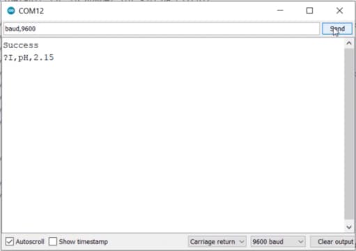
But this can be used to change the sensor mode from I2C to UART. To do that Type I and send. So a success message will appear again. Now type “baud,9600” and hit the send button. The LED color will immediately change to green again.
Using EZO I2C library
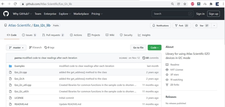
The above I2C code didn’t work with this sensor. So we will use the EZO I2C library to get the Ph Sensor stable reading.
The GitHub repository for this EZO I2C Library contains so many examples code. You can follow the codes if you are developing some systems. Meanwhile, I will just use this library to read the sensor value in I2C Mode.
Enable the I2C Mode of the sensor and use the correct wiring again. Copy the following code and paste in the Arduino IDE.
|
1 2 3 4 5 6 7 8 9 10 11 12 13 14 15 16 17 18 19 20 21 22 23 24 25 26 27 28 29 30 31 32 33 34 35 36 37 38 39 40 41 42 43 44 45 46 47 48 49 50 51 52 53 54 55 56 57 58 59 60 61 62 63 64 65 |
#include <Ezo_i2c.h> // Link: https://github.com/Atlas-Scientific/Ezo_I2c_lib) #include <Wire.h> //include arduinos i2c library Ezo_board PH = Ezo_board(99, "PH"); //create a PH circuit object, who's address is 99 and name is "PH" bool reading_request_phase = true; //selects our phase uint32_t next_poll_time = 0; //holds the next time we receive a response, in milliseconds const unsigned int response_delay = 1000; //how long we wait to receive a response, in milliseconds void setup() { Wire.begin(); //start the I2C Serial.begin(9600); //start the serial communication to the computer at baud rate of 9600 } void loop() { if (reading_request_phase) //if were in the phase where we ask for a reading { //send a read command. we use this command instead of PH.send_cmd("R"); //to let the library know to parse the reading PH.send_read_cmd(); next_poll_time = millis() + response_delay; //set when the response will arrive reading_request_phase = false; //switch to the receiving phase } else //if were in the receiving phase { if (millis() >= next_poll_time) //and its time to get the response { receive_reading(PH); //get the reading from the PH circuit reading_request_phase = true; //switch back to asking for readings } } } void receive_reading(Ezo_board &Sensor) // function to decode the reading after the read command was issued { Serial.print(Sensor.get_name()); // print the name of the circuit getting the reading Serial.print(": "); Sensor.receive_read_cmd(); //get the response data and put it into the [Sensor].reading variable if successful switch (Sensor.get_error()) //switch case based on what the response code is. { case Ezo_board::SUCCESS: Serial.println(Sensor.get_last_received_reading()); //the command was successful, print the reading break; case Ezo_board::FAIL: Serial.print("Failed "); //means the command has failed. break; case Ezo_board::NOT_READY: Serial.print("Pending "); //the command has not yet been finished calculating. break; case Ezo_board::NO_DATA: Serial.print("No Data "); //the sensor has no data to send. break; } } |
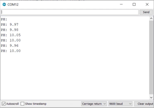
Now you can upload the code to the Arduino Board.
After uploading, open the serial monitor. The sensor is giving the correct reading once again.
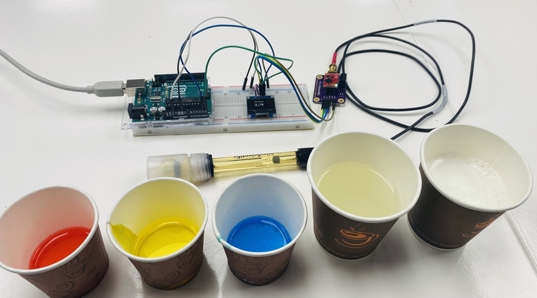
Atlas Ph Sensor Calibration
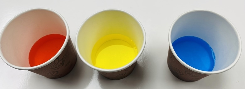
Let us see how we can do the calibration of Atlas Ph Sensor. There are 3 pouches of Ph Solution that you get with the sensor kit. Put this solution in 3 different glasses. The red one is the ph 4, the yellow is the ph 7 and the blue is the ph 10.
Assemble the Arduino Ph Sensor circuit for UART Mode & upload the UART Code. We will do the calibration using the UART code. Upload the UART Code and then open the Serial Monitor.
The Ph Sensor is placed in the buffer solution. Remove the sensor cap and rinse it with water.

Wait for the sensor reading to get stable. It may take 5-10 minutes for the reading to get a stable reading. Now once the reading get stable, you can start the calibration process.

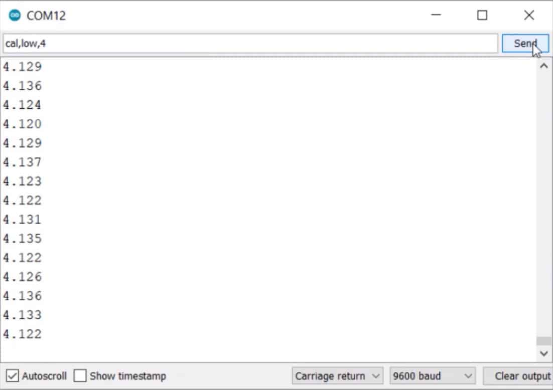
Now put the Ph Probe in the ph 4 solution and type the following command.
“cal,4,low”
Then hit the send button. The sensor will be calibrated for ph value 4.
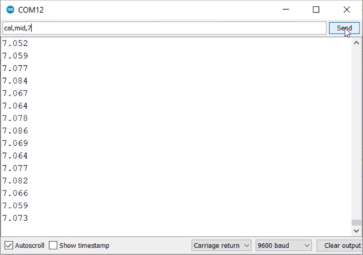
Now remove the sensor from ph 4 solution and rinse it with water. Then put it to the ph 7 solutions. In this box, again type the following command.
“cal,7,mid”
Then hit the send button. So the sensor is calibrated for ph value 7.
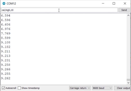
Repeat this again with Ph 10 solution. Remove the sensor rinse with water and put it In ph 10 solution. In this box, again type the following command.
“cal,10,high”
Hit the send button, the sensor is calibrated for ph value 10.
This is how you can do the Calibration of Atlas Ph Sensor.
Portable Ph Meter with OLED Display
Let us make a portable Ph Meter by interfacing Atlas Ph Sensor Kit with Arduino & OLED Display. You can again use the I2C or UART connection between Atlas Ph Sensor and Arduino. But I used I2C Connection as we will be using EZO pH Library. The OLED Display is an I2C module so the I2C connection remains similar to that of Ph Sensor.

You can use a breadboard for the connection. Only 4 wires are connected to the Arduino UNO board, i.e the 3.3V, GND, SDA & SCL pin.
Source Code/program
The code is again the same, but this time we have added the SSD1306 OLED Library and Adafruit GFX Library. Then we print the Ph value on OLED Screen.
|
1 2 3 4 5 6 7 8 9 10 11 12 13 14 15 16 17 18 19 20 21 22 23 24 25 26 27 28 29 30 31 32 33 34 35 36 37 38 39 40 41 42 43 44 45 46 47 48 49 50 51 52 53 54 55 56 57 58 59 60 61 62 63 64 65 66 67 68 69 70 71 72 73 74 75 76 77 78 79 80 81 82 83 84 85 86 87 88 89 90 91 92 93 94 95 |
#include <Wire.h> //include arduinos i2c library #include <Ezo_i2c.h> // Link: https://github.com/Atlas-Scientific/Ezo_I2c_lib) #include <Adafruit_GFX.h> #include <Adafruit_SSD1306.h> #define SCREEN_WIDTH 128 // OLED display width, in pixels #define SCREEN_HEIGHT 64 // OLED display height, in pixels #define OLED_RESET -1 // Reset pin # (or -1 if sharing Arduino reset pin) Ezo_board PH = Ezo_board(99, "PH"); //create a PH circuit object, who's address is 99 and name is "PH" bool reading_request_phase = true; //selects our phase uint32_t next_poll_time = 0; //holds the next time we receive a response, in milliseconds const unsigned int response_delay = 1000; //how long we wait to receive a response, in milliseconds Adafruit_SSD1306 display(SCREEN_WIDTH, SCREEN_HEIGHT, &Wire, OLED_RESET); void setup() { Wire.begin(); //start the I2C Serial.begin(9600); //start the serial communication to the computer at baud rate of 9600 display.begin(SSD1306_SWITCHCAPVCC, 0x3C); //initialize with the I2C addr 0x3C (128x64) display.clearDisplay(); } void loop() { if (reading_request_phase) //if were in the phase where we ask for a reading { //send a read command. we use this command instead of PH.send_cmd("R"); //to let the library know to parse the reading PH.send_read_cmd(); next_poll_time = millis() + response_delay; //set when the response will arrive reading_request_phase = false; //switch to the receiving phase } else //if were in the receiving phase { if (millis() >= next_poll_time) //and its time to get the response { receive_reading(PH); //get the reading from the PH circuit reading_request_phase = true; //switch back to asking for readings } } } void receive_reading(Ezo_board &Sensor) // function to decode the reading after the read command was issued { Serial.print(Sensor.get_name()); // print the name of the circuit getting the reading Serial.print(": "); display.setTextColor(WHITE); display.setCursor(30, 10); //oled display display.setTextSize(1); display.print("Ph Value:"); Sensor.receive_read_cmd(); //get the response data and put it into the [Sensor].reading variable if successful switch (Sensor.get_error()) //switch case based on what the response code is. { case Ezo_board::SUCCESS: Serial.println(Sensor.get_last_received_reading()); //the command was successful, print the reading display.setCursor(30, 30); //oled display display.setTextSize(2); display.print(Sensor.get_last_received_reading()); break; case Ezo_board::FAIL: Serial.print("Failed "); //means the command has failed. display.setCursor(30, 30); //oled display display.setTextSize(2); display.print("Failed"); break; case Ezo_board::NOT_READY: Serial.print("Pending "); //the command has not yet been finished calculating. display.setCursor(30, 30); //oled display display.setTextSize(2); display.print("Pending"); break; case Ezo_board::NO_DATA: Serial.print("No Data "); //the sensor has no data to send. display.setCursor(30, 30); //oled display display.setTextSize(2); display.print("No Data1`"); break; } display.display(); delay(250); display.clearDisplay(); } |
After uploading the code, it’s time to test the ph sensor. We used five different solutions for testing. Three are default standard ph solutions of 4, 7, and 10 & the other two are water and milk powder solutions.
First, rinse the sensor. While rinsing, the OLED will display the Ph value of water, which is lesser than 7.
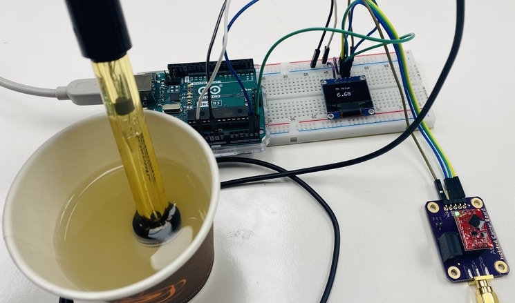
After rinsing put the sensor in ph 4 solution, the OLED will display the reading as 4. Do the same thing for ph solutions of 7 and 10.
For ph solution 7 the reading will be around 7.

The reading for the Ph solution of 10 will be 10.

The Ph for milk powder solution is lesser than 7 which indicates milk is acidic in nature.
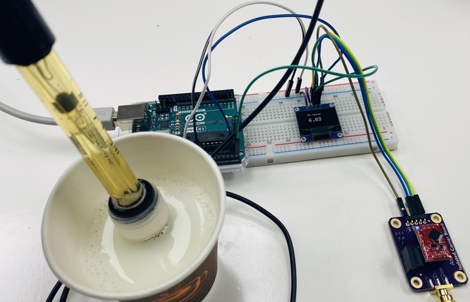
In this way, you can measure the ph of different solutions using this portable Ph Meter.
Video Tutorial & Guide


")


1 Comment
Thank you for the working code for the circuit, I too tried the official provided code from Atlas, however it didn’t work.