

Overview
In this article, we will learn how to monitor Aquarium Water Quality with TDS Sensor, Temperature Sensor, ESP32 WIFI Module & TFT LCD Display. An aquarium is a receptacle for maintaining aquatic organisms, either freshwater or marine, or a facility in which a collection of aquatic organisms is displayed or studied.
In a Smart Aquarium, it is necessary to monitor the water quality as well as automatic water changing and also automatic feeding. Water quality monitoring is the most complicated task as it requires the use of sensors and electronic equipment. The water quality parameters include Water pH, TDS, Turbidity, Dissolved Oxygen, Temperature, Electrical Conductivity, etc. But for aquariums & aquatic life including fish, the most important parameter is the Water Temperature and TDS. For an aquarium, the temperature good range is 76° to 80°F (25° to 27°C). The 400PPM~450PPM TDS in the water are recommended for most freshwater fish living.

In this project, we will build our own Aquarium Water Quality Monitor System with TDS Sensor & ESP32. We will display the real-time value of Water TDS and Temperature on the TFT Color LCD Display. The informations related to TDS Sensor and DS18B20 Waterproof Temperature Sensor are already available on previous posts. The best thing about the project is the use of TFT LCD Display embedded with ESP32. The cutomized Display is designed by Makerfabs.
Bill of Materials
To make a Aquarium Water Quality Monitoring System, we need the following components. You can purchase all these components online from the given link.
| S.N. | Components Name | Quantity | Purchase Links |
|---|---|---|---|
| 1 | ESP32 + LCD Display | 1 | Makerfabs Link |
| 2 | Gravity Analog TDS Sensor | 1 | Amazon | AliExpress |
| 4 | DS18B20 Temperature Sensor | 1 | Amazon | AliExpress |
| 5 | Resistor 4.7K | 1 | Amazon | AliExpress |
| 6 | Connecting Wires | 10 | Amazon | AliExpress |
| 7 | Breadboard | 1 | Amazon | AliExpress |
What is TDS & How it affects Fish Life?
The TDS value (Total Dissolved Solids) gives the sum of dissolved solids in water. These solids include for instance salts, minerals, and conductive metals ions. The value is additionally called the conductivity of the water. Because the more such solids or ions are within the water, the higher it conducts electricity.
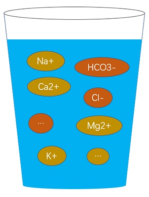
TDS meters typically quantify this conductivity in micro siemens or ppm. The latter stands for parts per million, i.e. the number of solid particles per million water mixture particles. The value of 40 ppm means from a million particles there are 40 dissolved ions and therefore the rest (= 999 960) are water molecules.
How Does TDS Affect Fish & other Aquatic life?
The fishes need a stable environment that has the same level of TDS and PH as the original habit in aquariums or tanks. Different fishes require water with different TDS. 400PPM~450PPM TDS in the water are recommended for most freshwater fish living.
If the concentrations are too high, it would cause the death of fish and permit a high volume of algae bloom. The low level of TDS in the water will affect fish growth. In a word, if the TDS climbs above normal levels, you may need to help the small fish.
Gravity TDS Sensor
Gravity Analog TDS Sensor is an Arduino-compatible TDS sensor/Meter Kit for measuring TDS value of the water. It can be applied to domestic water, hydroponic and other fields of water quality testing. This product supports 3.3 ~ 5.5V wide voltage input, and 0 ~ 2.3V analog voltage output, which makes it compatible with 5V or 3.3V control systems or boards.

The excitation source is an AC signal, which can effectively prevent the probe from polarization and prolong the life of the probe, meanwhile, it can help increase the stability of the output signal. The TDS probe is waterproof, it can be immersed in water for long time measurement.
The sensor has a TDS Measurement Range between 0 ~ 1000ppm with an accuracy of 10% FS (25 ℃). The probe can not to be used in water above 55 degrees centigrade.
DS18B20 Waterproof Temperature Sensor
This is a pre-wired and waterproofed version of the DS18B20 Sensor used to measure something far away, or in wet conditions. The Sensor can measure the temperature between -55 to 125°C (-67°F to +257°F). The cable is jacketed in PVC. These 1-wire digital temperature sensors are fairly precise, i.e ±0.5°C over much of the range. They work great with any microcontroller using a single digital pin.

The sensor requires two libraries like Dallas Temperature Sensor Library & One-Wire Library. It also requires a 4.7k resistor, which is required as a pullup from the DATA to the VCC line when using the sensor. To learn more about this sensor you can go through the previous post: DS18B20 Sensor Tutorial.
Interfacing TDS & Temperature Sensor with ESP32
Now, let us interface the Gravity TDS Sensor & DS18B20 Temperature Sensor with ESP32 Board. The reason why we are using a temperature sensor is that the temperature parameter is required during TDS compensation. The TDS values change a lot with rising and falling in temperature.
Here is the simple connection diagram for the project.

Connect the TDS & Temperature Sensor VCC & GND Pin to ESP32 3.3V & GND Pin respectively. Connect the output analog pin of the TDS Sensor to ESP32 IO35 Pin. Similarly, connect the output of DS18B20 to ESP32 IO25 Pin. A 4.7K pull of resistor is necessary and requires a connection between the DS18B20 output pin & 3.3V VCC as a parasitic power.

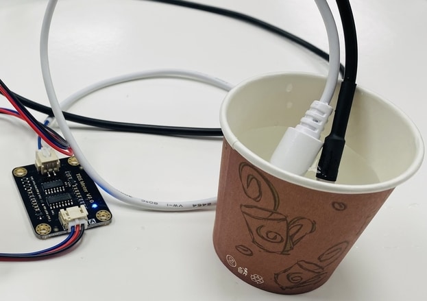
You may assemble the components on a breadboard for testing purposes.
Source Code/Program
Here is a simple test code for testing the working of TDS Sensor & Temperature Sensor with ESP32. The DS18B20 temperature sensor requires a One-wire Library as well as Dallas Library.
Download these libraries and add them to the Arduino IDE library folder. Now, you can upload the following code to the ESP32 Board.
|
1 2 3 4 5 6 7 8 9 10 11 12 13 14 15 16 17 18 19 20 21 22 23 24 25 26 27 28 29 30 31 32 33 34 35 36 37 38 39 40 41 42 43 44 45 46 47 48 49 50 51 52 53 54 55 56 57 58 59 60 61 62 63 64 65 66 67 68 69 70 71 72 73 74 75 76 77 78 79 80 81 82 83 84 85 86 |
#include <OneWire.h> #include <DallasTemperature.h> const int oneWireBus = 25; // GPIO where the DS18B20 is connected to #define TdsSensorPin 35 #define VREF 3.3 // analog reference voltage(Volt) of the ADC #define SCOUNT 30 // sum of sample point int analogBuffer[SCOUNT]; // store the analog value in the array, read from ADC int analogBufferTemp[SCOUNT]; int analogBufferIndex = 0; int copyIndex = 0; float averageVoltage = 0; float tdsValue = 0; float temperature = 0; OneWire oneWire(oneWireBus); // Setup a oneWire instance to communicate with any OneWire devices DallasTemperature sensors(&oneWire); // Pass our oneWire reference to Dallas Temperature sensor void setup() { Serial.begin(115200); pinMode(TdsSensorPin, INPUT); sensors.begin(); } void loop() { sensors.requestTemperatures(); float temperature = sensors.getTempCByIndex(0); static unsigned long analogSampleTimepoint = millis(); if (millis() - analogSampleTimepoint > 40U) //every 40 milliseconds,read the analog value from the ADC { analogSampleTimepoint = millis(); analogBuffer[analogBufferIndex] = analogRead(TdsSensorPin); //read the analog value and store into the buffer analogBufferIndex++; if (analogBufferIndex == SCOUNT) analogBufferIndex = 0; } static unsigned long printTimepoint = millis(); if (millis() - printTimepoint > 800U) { printTimepoint = millis(); for (copyIndex = 0; copyIndex < SCOUNT; copyIndex++) analogBufferTemp[copyIndex] = analogBuffer[copyIndex]; averageVoltage = getMedianNum(analogBufferTemp, SCOUNT) * (float)VREF / 1024.0; // read the analog value more stable by the median filtering algorithm, and convert to voltage value float compensationCoefficient = 1.0 + 0.02 * (temperature - 25.0); //temperature compensation formula: fFinalResult(25^C) = fFinalResult(current)/(1.0+0.02*(fTP-25.0)); float compensationVolatge = averageVoltage / compensationCoefficient; //temperature compensation tdsValue = (133.42 * compensationVolatge * compensationVolatge * compensationVolatge - 255.86 * compensationVolatge * compensationVolatge + 857.39 * compensationVolatge) * 0.5; //convert voltage value to tds value Serial.print("TDS Value:"); Serial.print(tdsValue, 0); Serial.println("ppm"); Serial.print("Temperature:"); Serial.print(temperature); Serial.println("ºC"); } } int getMedianNum(int bArray[], int iFilterLen) { int bTab[iFilterLen]; for (byte i = 0; i < iFilterLen; i++) bTab[i] = bArray[i]; int i, j, bTemp; for (j = 0; j < iFilterLen - 1; j++) { for (i = 0; i < iFilterLen - j - 1; i++) { if (bTab[i] > bTab[i + 1]) { bTemp = bTab[i]; bTab[i] = bTab[i + 1]; bTab[i + 1] = bTemp; } } } if ((iFilterLen & 1) > 0) bTemp = bTab[(iFilterLen - 1) / 2]; else bTemp = (bTab[iFilterLen / 2] + bTab[iFilterLen / 2 - 1]) / 2; return bTemp; } |
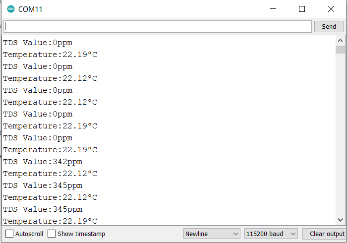
After uploading the code, open the Serial Monitor. Also, dip the TDS & Temperature Sensor probe in a water sample.
Observe the Serial Monitor, it will start displaying the reading of both temperature and TDS value.
The TDS Value can also be converted into EC Value & thus EC Meter with ESP32 can be designed for Drinking Water Quality Monitoring System.
Aquarium Water Quality Monitor with TDS Sensor & ESP32
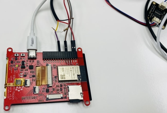
Now lets add a display to the above project and build a display based portable Water TDS Meter. One of the best display that comes integrated with ESP32 & ILI9341 3.5″ TFT Touch Display.
The display can be very useful to monitor Aquarium Water Monitor for fish and other aquatic life. The connection diagram for the project is again simple as shown.

The connection for the GPIO Pins stills remains the same.
Source Code/Program
Let us use the ESP32 & LCD Screen along with TDS & Temperature sensor. The LCD Screen will display the value of temperature & TDS level in Gauge format.
The below code uses two files one as a .ino file and the other as a .h file.
Copy the following code and paste it on your Arduino IDE and save it in .ino format.
|
1 2 3 4 5 6 7 8 9 10 11 12 13 14 15 16 17 18 19 20 21 22 23 24 25 26 27 28 29 30 31 32 33 34 35 36 37 38 39 40 41 42 43 44 45 46 47 48 49 50 51 52 53 54 55 56 57 58 59 60 61 62 63 64 65 66 67 68 69 70 71 72 73 74 75 76 77 78 79 80 81 82 83 84 85 86 87 88 89 90 91 92 93 94 95 96 97 98 99 100 101 102 103 104 105 106 107 108 109 110 111 112 113 114 115 116 117 118 119 120 121 122 123 124 125 126 127 128 129 130 131 132 133 134 135 136 137 138 139 140 141 142 143 144 145 146 147 148 149 150 151 152 153 154 155 156 157 158 159 160 161 162 163 164 165 166 167 168 169 170 171 172 173 174 175 176 177 178 179 180 181 182 183 184 185 186 187 188 189 190 191 192 193 194 195 196 197 198 199 200 201 202 203 204 205 206 207 208 209 210 211 212 213 214 215 216 217 218 219 220 221 222 223 224 225 226 227 228 229 230 231 232 233 234 235 236 237 238 239 240 241 242 243 244 245 246 247 248 249 250 251 252 253 254 255 256 257 258 259 260 261 262 263 264 265 266 267 268 269 270 271 272 273 274 275 276 277 278 279 280 281 282 283 284 285 286 287 288 289 290 291 292 293 294 295 296 297 298 299 300 301 302 303 304 305 306 307 308 309 310 311 312 313 314 315 316 317 318 319 320 321 322 323 324 325 326 327 328 329 330 331 332 333 334 335 336 337 338 339 340 341 342 343 344 345 346 347 348 349 350 351 352 353 354 355 356 357 358 359 360 361 362 363 364 365 366 367 368 369 370 371 372 373 374 375 376 377 378 379 380 381 382 |
#include <OneWire.h> #include <DallasTemperature.h> #include "alert.h" // Out of range alert icon #include <TFT_eSPI.h> // Hardware-specific library #include <SPI.h> const int oneWireBus = 25; // GPIO where the DS18B20 is connected to #define TdsSensorPin 35 #define VREF 3.3 // analog reference voltage(Volt) of the ADC #define SCOUNT 30 // sum of sample point #define RED2RED 0 #define GREEN2GREEN 1 #define BLUE2BLUE 2 #define BLUE2RED 3 #define GREEN2RED 4 #define RED2GREEN 5 #define TFT_GREY 0x2104 // Dark grey 16 bit colour TFT_eSPI tft = TFT_eSPI(); // Invoke custom library with default width and height uint32_t runTime = -99999; // time for next update int analogBuffer[SCOUNT]; // store the analog value in the array, read from ADC int analogBufferTemp[SCOUNT]; int analogBufferIndex = 0; int copyIndex = 0; float averageVoltage = 0; float tdsValue = 0; float temperature = 0; int reading = 0; // Value to be displayed int d = 0; // Variable used for the sinewave test waveform boolean range_error = 0; int8_t ramp = 1; OneWire oneWire(oneWireBus); // Setup a oneWire instance to communicate with any OneWire devices DallasTemperature sensors(&oneWire); // Pass our oneWire reference to Dallas Temperature sensor void setup(void) { Serial.begin(115200); sensors.begin(); pinMode(TdsSensorPin, INPUT); tft.begin(); tft.setRotation(1); tft.fillScreen(TFT_BLACK); tft.setTextColor(TFT_WHITE, TFT_BLACK); tft.drawString("Aquarium Monitoring", 120, 10, 4); //tft.drawString("Weather", 350, 10, 2); tft.drawString("TDS Value", 80, 270, 2); tft.drawString("Temperature", 320, 270, 2); } void loop() { tdstemp_read(); if (millis() - runTime >= 0L) { // Execute every TBD ms runTime = millis(); // Test with a slowly changing value from a Sine function d += 4; if (d >= 360) d = 0; // Set the the position, gap between meters, and inner radius of the meters int xpos = 0, ypos = 5, gap = 4, radius = 52; xpos = 60, ypos = 90, gap = 50, radius = 80; //reading = 800 + 150 * sineWave(d + 90); xpos = gap + ringMeter(tdsValue, 0, 1000, xpos, ypos, radius, "ppm", BLUE2RED); // Draw analogue meter //reading = 15 + 15 * sineWave(d + 150); xpos = gap + ringMeter(temperature, -20, 50, xpos, ypos, radius, "C", GREEN2GREEN); // Draw analogue meter } } // ######################################################################### // Draw the meter on the screen, returns x coord of righthand side // ######################################################################### int ringMeter(int value, int vmin, int vmax, int x, int y, int r, const char *units, byte scheme) { // Minimum value of r is about 52 before value text intrudes on ring // drawing the text first is an option x += r; y += r; // Calculate coords of centre of ring int w = r / 3; // Width of outer ring is 1/4 of radius int angle = 150; // Half the sweep angle of meter (300 degrees) int v = map(value, vmin, vmax, -angle, angle); // Map the value to an angle v byte seg = 3; // Segments are 3 degrees wide = 100 segments for 300 degrees byte inc = 6; // Draw segments every 3 degrees, increase to 6 for segmented ring // Variable to save "value" text colour from scheme and set default int colour = TFT_BLUE; // Draw colour blocks every inc degrees for (int i = -angle + inc / 2; i < angle - inc / 2; i += inc) { // Calculate pair of coordinates for segment start float sx = cos((i - 90) * 0.0174532925); float sy = sin((i - 90) * 0.0174532925); uint16_t x0 = sx * (r - w) + x; uint16_t y0 = sy * (r - w) + y; uint16_t x1 = sx * r + x; uint16_t y1 = sy * r + y; // Calculate pair of coordinates for segment end float sx2 = cos((i + seg - 90) * 0.0174532925); float sy2 = sin((i + seg - 90) * 0.0174532925); int x2 = sx2 * (r - w) + x; int y2 = sy2 * (r - w) + y; int x3 = sx2 * r + x; int y3 = sy2 * r + y; if (i < v) { // Fill in coloured segments with 2 triangles switch (scheme) { case 0: colour = TFT_RED; break; // Fixed colour case 1: colour = TFT_GREEN; break; // Fixed colour case 2: colour = TFT_BLUE; break; // Fixed colour case 3: colour = rainbow(map(i, -angle, angle, 0, 127)); break; // Full spectrum blue to red case 4: colour = rainbow(map(i, -angle, angle, 70, 127)); break; // Green to red (high temperature etc) case 5: colour = rainbow(map(i, -angle, angle, 127, 63)); break; // Red to green (low battery etc) default: colour = TFT_BLUE; break; // Fixed colour } tft.fillTriangle(x0, y0, x1, y1, x2, y2, colour); tft.fillTriangle(x1, y1, x2, y2, x3, y3, colour); //text_colour = colour; // Save the last colour drawn } else // Fill in blank segments { tft.fillTriangle(x0, y0, x1, y1, x2, y2, TFT_GREY); tft.fillTriangle(x1, y1, x2, y2, x3, y3, TFT_GREY); } } // Convert value to a string char buf[10]; byte len = 3; if (value > 999) len = 5; dtostrf(value, len, 0, buf); buf[len] = ' '; buf[len + 1] = 0; // Add blanking space and terminator, helps to centre text too! // Set the text colour to default tft.setTextSize(1); if (value < vmin || value > vmax) { drawAlert(x, y + 90, 50, 1); } else { drawAlert(x, y + 90, 50, 0); } tft.setTextColor(TFT_WHITE, TFT_BLACK); // Uncomment next line to set the text colour to the last segment value! tft.setTextColor(colour, TFT_BLACK); tft.setTextDatum(MC_DATUM); // Print value, if the meter is large then use big font 8, othewise use 4 if (r > 84) { tft.setTextPadding(55 * 3); // Allow for 3 digits each 55 pixels wide tft.drawString(buf, x, y, 8); // Value in middle } else { tft.setTextPadding(3 * 14); // Allow for 3 digits each 14 pixels wide tft.drawString(buf, x, y, 4); // Value in middle } tft.setTextSize(1); tft.setTextPadding(0); // Print units, if the meter is large then use big font 4, othewise use 2 tft.setTextColor(TFT_WHITE, TFT_BLACK); if (r > 84) tft.drawString(units, x, y + 60, 4); // Units display else tft.drawString(units, x, y + 15, 2); // Units display // Calculate and return right hand side x coordinate return x + r; } void drawAlert(int x, int y, int side, boolean draw) { if (draw && !range_error) { drawIcon(alert, x - alertWidth / 2, y - alertHeight / 2, alertWidth, alertHeight); range_error = 1; } else if (!draw) { tft.fillRect(x - alertWidth / 2, y - alertHeight / 2, alertWidth, alertHeight, TFT_BLACK); range_error = 0; } } // ######################################################################### // Return a 16 bit rainbow colour // ######################################################################### unsigned int rainbow(byte value) { // Value is expected to be in range 0-127 // The value is converted to a spectrum colour from 0 = blue through to 127 = red byte red = 0; // Red is the top 5 bits of a 16 bit colour value byte green = 0; // Green is the middle 6 bits byte blue = 0; // Blue is the bottom 5 bits byte quadrant = value / 32; if (quadrant == 0) { blue = 31; green = 2 * (value % 32); red = 0; } if (quadrant == 1) { blue = 31 - (value % 32); green = 63; red = 0; } if (quadrant == 2) { blue = 0; green = 63; red = value % 32; } if (quadrant == 3) { blue = 0; green = 63 - 2 * (value % 32); red = 31; } return (red << 11) + (green << 5) + blue; } // ######################################################################### // Return a value in range -1 to +1 for a given phase angle in degrees // ######################################################################### float sineWave(int phase) { return sin(phase * 0.0174532925); } //==================================================================================== // This is the function to draw the icon stored as an array in program memory (FLASH) //==================================================================================== // To speed up rendering we use a 64 pixel buffer #define BUFF_SIZE 64 // Draw array "icon" of defined width and height at coordinate x,y // Maximum icon size is 255x255 pixels to avoid integer overflow void drawIcon(const unsigned short *icon, int16_t x, int16_t y, int8_t width, int8_t height) { uint16_t pix_buffer[BUFF_SIZE]; // Pixel buffer (16 bits per pixel) tft.startWrite(); // Set up a window the right size to stream pixels into tft.setAddrWindow(x, y, width, height); // Work out the number whole buffers to send uint16_t nb = ((uint16_t)height * width) / BUFF_SIZE; // Fill and send "nb" buffers to TFT for (int i = 0; i < nb; i++) { for (int j = 0; j < BUFF_SIZE; j++) { pix_buffer[j] = pgm_read_word(&icon[i * BUFF_SIZE + j]); } tft.pushColors(pix_buffer, BUFF_SIZE); } // Work out number of pixels not yet sent uint16_t np = ((uint16_t)height * width) % BUFF_SIZE; // Send any partial buffer left over if (np) { for (int i = 0; i < np; i++) pix_buffer[i] = pgm_read_word(&icon[nb * BUFF_SIZE + i]); tft.pushColors(pix_buffer, np); } tft.endWrite(); } void tdstemp_read() { sensors.requestTemperatures(); temperature = sensors.getTempCByIndex(0); static unsigned long analogSampleTimepoint = millis(); if (millis() - analogSampleTimepoint > 40U) //every 40 milliseconds,read the analog value from the ADC { analogSampleTimepoint = millis(); analogBuffer[analogBufferIndex] = analogRead(TdsSensorPin); //read the analog value and store into the buffer analogBufferIndex++; if (analogBufferIndex == SCOUNT) analogBufferIndex = 0; } static unsigned long printTimepoint = millis(); if (millis() - printTimepoint > 800U) { printTimepoint = millis(); for (copyIndex = 0; copyIndex < SCOUNT; copyIndex++) analogBufferTemp[copyIndex] = analogBuffer[copyIndex]; averageVoltage = getMedianNum(analogBufferTemp, SCOUNT) * (float)VREF / 1024.0; // read the analog value more stable by the median filtering algorithm, and convert to voltage value float compensationCoefficient = 1.0 + 0.02 * (temperature - 25.0); //temperature compensation formula: fFinalResult(25^C) = fFinalResult(current)/(1.0+0.02*(fTP-25.0)); float compensationVolatge = averageVoltage / compensationCoefficient; //temperature compensation tdsValue = (133.42 * compensationVolatge * compensationVolatge * compensationVolatge - 255.86 * compensationVolatge * compensationVolatge + 857.39 * compensationVolatge) * 0.5; //convert voltage value to tds value Serial.print("TDS Value:"); Serial.print(tdsValue, 0); Serial.println("ppm"); Serial.print("Temperature:"); Serial.print(temperature); Serial.println("ºC"); } } int getMedianNum(int bArray[], int iFilterLen) { int bTab[iFilterLen]; for (byte i = 0; i < iFilterLen; i++) bTab[i] = bArray[i]; int i, j, bTemp; for (j = 0; j < iFilterLen - 1; j++) { for (i = 0; i < iFilterLen - j - 1; i++) { if (bTab[i] > bTab[i + 1]) { bTemp = bTab[i]; bTab[i] = bTab[i + 1]; bTab[i + 1] = bTemp; } } } if ((iFilterLen & 1) > 0) bTemp = bTab[(iFilterLen - 1) / 2]; else bTemp = (bTab[iFilterLen / 2] + bTab[iFilterLen / 2 - 1]) / 2; return bTemp; } |
Open a new tab in Arduino IDE. Copy the following code and save it as Alert. h file.
|
1 2 3 4 5 6 7 8 9 10 11 12 13 14 15 16 17 18 19 20 21 22 23 24 25 26 27 28 29 30 31 32 33 34 35 36 37 38 39 40 41 |
// We need this header file to use FLASH as storage with PROGMEM directive: #include <pgmspace.h> // Icon width and height const uint16_t alertWidth = 32; const uint16_t alertHeight = 32; // The icon file can be created with the "UTFT ImageConverter 565" bitmap to .c file creation utility, more can be pasted in here const unsigned short alert[1024] PROGMEM={ 0x0000,0x0000,0x0000,0x0000,0x0000,0x0000,0x0000,0x0000,0x0000,0x0000,0x0000,0x0000,0x0000,0x0000,0x0000,0x0000,0x0840,0x0000,0x0000,0x0000,0x0000,0x0000,0x0000,0x0000,0x0000,0x0000,0x0000,0x0000,0x0000,0x0000,0x0000,0x0000, // row 0, 32 pixels 0x0000,0x0000,0x0000,0x0000,0x0000,0x0000,0x0000,0x0000,0x0000,0x0000,0x0000,0x0000,0x0000,0x1080,0xAC66,0xEDE8,0xFE69,0xC4C6,0x2901,0x0000,0x0000,0x0000,0x0000,0x0000,0x0000,0x0000,0x0000,0x0000,0x0000,0x0000,0x0000,0x0000, // row 1, 64 pixels 0x0000,0x0000,0x0000,0x0000,0x0000,0x0000,0x0000,0x0000,0x0000,0x0000,0x0000,0x0000,0x0000,0xBCC6,0xFE68,0xFE68,0xFE6A,0xFE68,0xEDE8,0x18A1,0x0000,0x0000,0x0000,0x0000,0x0000,0x0000,0x0000,0x0000,0x0000,0x0000,0x0000,0x0000, // row 2, 96 pixels 0x0000,0x0000,0x0000,0x0000,0x0000,0x0000,0x0000,0x0000,0x0000,0x0000,0x0000,0x0000,0x8344,0xFE48,0xFE8C,0xFFDD,0xFFFF,0xFEF0,0xFE48,0xB466,0x0000,0x0000,0x0000,0x0000,0x0000,0x0000,0x0000,0x0000,0x0000,0x0000,0x0000,0x0000, // row 3, 128 pixels 0x0000,0x0000,0x0000,0x0000,0x0000,0x0000,0x0000,0x0000,0x0000,0x0000,0x0000,0x1880,0xEDC7,0xFE48,0xFF99,0xFFBC,0xFF9B,0xFFBD,0xFE6A,0xFE48,0x5A23,0x0000,0x0000,0x0000,0x0000,0x0000,0x0000,0x0000,0x0000,0x0000,0x0000,0x0000, // row 4, 160 pixels 0x0000,0x0000,0x0000,0x0000,0x0000,0x0000,0x0000,0x0000,0x0000,0x0000,0x0000,0x9BE5,0xFE28,0xFED0,0xFFBC,0xFF7A,0xFF9A,0xFF9B,0xFF35,0xFE28,0xBCA6,0x0000,0x0000,0x0000,0x0000,0x0000,0x0000,0x0000,0x0000,0x0000,0x0000,0x0000, // row 5, 192 pixels 0x0000,0x0000,0x0000,0x0000,0x0000,0x0000,0x0000,0x0000,0x0000,0x0000,0x3962,0xFE28,0xFE28,0xFF9A,0xFF79,0xFF9A,0xFF9B,0xFF9A,0xFFBD,0xFE6B,0xFE28,0x72E3,0x0000,0x0000,0x0000,0x0000,0x0000,0x0000,0x0000,0x0000,0x0000,0x0000, // row 6, 224 pixels 0x0000,0x0000,0x0000,0x0000,0x0000,0x0000,0x0000,0x0000,0x0000,0x0000,0xB465,0xFE28,0xFEF2,0xFF7A,0xFF79,0xFF7A,0xFF9A,0xFF7A,0xFF7A,0xFF78,0xFE28,0xDD67,0x0860,0x0000,0x0000,0x0000,0x0000,0x0000,0x0000,0x0000,0x0000,0x0000, // row 7, 256 pixels 0x0000,0x0000,0x0000,0x0000,0x0000,0x0000,0x0000,0x0000,0x0000,0x5A22,0xFE07,0xFE29,0xFF9B,0xFF37,0xFF58,0xFF79,0xFF79,0xFF79,0xFF58,0xFF9B,0xFEAE,0xFE07,0x93A4,0x0000,0x0000,0x0000,0x0000,0x0000,0x0000,0x0000,0x0000,0x0000, // row 8, 288 pixels 0x0000,0x0000,0x0000,0x0000,0x0000,0x0000,0x0000,0x0000,0x0000,0xC4A5,0xFE07,0xFF15,0xFF37,0xFF36,0xAD11,0x2965,0x2965,0xCDF4,0xFF37,0xFF37,0xFF79,0xFE07,0xFE07,0x2901,0x0000,0x0000,0x0000,0x0000,0x0000,0x0000,0x0000,0x0000, // row 9, 320 pixels 0x0000,0x0000,0x0000,0x0000,0x0000,0x0000,0x0000,0x0000,0x7B03,0xFDE7,0xFE4B,0xFF79,0xFEF4,0xFF15,0xB552,0x2945,0x2945,0xDE55,0xFF16,0xFF15,0xFF58,0xFED1,0xFDE7,0xAC25,0x0000,0x0000,0x0000,0x0000,0x0000,0x0000,0x0000,0x0000, // row 10, 352 pixels 0x0000,0x0000,0x0000,0x0000,0x0000,0x0000,0x0000,0x0840,0xDD26,0xFDE7,0xFF57,0xFED3,0xFED2,0xFEF4,0xBD93,0x2124,0x2124,0xDE75,0xFF14,0xFED3,0xFED3,0xFF7A,0xFE08,0xFDE7,0x49A2,0x0000,0x0000,0x0000,0x0000,0x0000,0x0000,0x0000, // row 11, 384 pixels 0x0000,0x0000,0x0000,0x0000,0x0000,0x0000,0x0000,0x9BA4,0xFDC6,0xFE6E,0xFF36,0xFE90,0xFEB1,0xFED3,0xC592,0x2124,0x2124,0xE675,0xFED3,0xFEB2,0xFEB1,0xFEF3,0xFEF3,0xFDC6,0xBC45,0x0000,0x0000,0x0000,0x0000,0x0000,0x0000,0x0000, // row 12, 416 pixels 0x0000,0x0000,0x0000,0x0000,0x0000,0x0000,0x3141,0xF5C6,0xF5C7,0xFF58,0xFE90,0xFE6F,0xFE8F,0xFEB1,0xCDB2,0x2104,0x2104,0xF6B4,0xFEB1,0xFE90,0xFE8F,0xFE90,0xFF58,0xFE0A,0xF5C6,0x72A3,0x0000,0x0000,0x0000,0x0000,0x0000,0x0000, // row 13, 448 pixels 0x0000,0x0000,0x0000,0x0000,0x0000,0x0000,0xABE4,0xF5A6,0xFEB1,0xFED3,0xFE4E,0xFE6E,0xFE6F,0xFE90,0xD5F2,0x18E3,0x18E3,0xFED4,0xFE90,0xFE6F,0xFE6F,0xFE6E,0xFE91,0xFF36,0xF5A6,0xCCA5,0x0000,0x0000,0x0000,0x0000,0x0000,0x0000, // row 14, 480 pixels 0x0000,0x0000,0x0000,0x0000,0x0000,0x5202,0xF5A6,0xF5C7,0xFF58,0xFE4D,0xFE4D,0xFE4D,0xFE4E,0xFE6F,0xDE11,0x18C3,0x18C3,0xFED3,0xFE6F,0xFE6E,0xFE4E,0xFE4D,0xFE4D,0xFF16,0xFE2C,0xF5A6,0x9363,0x0000,0x0000,0x0000,0x0000,0x0000, // row 15, 512 pixels 0x0000,0x0000,0x0000,0x0000,0x0000,0xBC44,0xF585,0xFED3,0xFE6F,0xFE2C,0xFE2C,0xFE2D,0xFE4D,0xFE4E,0xE630,0x10A2,0x2104,0xFED1,0xFE4E,0xFE4D,0xFE4D,0xFE2D,0xFE2C,0xFE4D,0xFF37,0xF586,0xF585,0x28E1,0x0000,0x0000,0x0000,0x0000, // row 16, 544 pixels 0x0000,0x0000,0x0000,0x0000,0x7282,0xF565,0xF5EA,0xFF16,0xFE0B,0xFE0B,0xFE0B,0xFE2C,0xFE2C,0xFE4D,0xF670,0x1082,0x2924,0xFEB0,0xFE2D,0xFE2C,0xFE2C,0xFE2C,0xFE0B,0xFE0B,0xFEB2,0xFE6F,0xF565,0xA383,0x0000,0x0000,0x0000,0x0000, // row 17, 576 pixels 0x0000,0x0000,0x0000,0x0840,0xD4C4,0xF565,0xFEF5,0xFE0C,0xFDE9,0xFDEA,0xFE0A,0xFE0B,0xFE0B,0xFE2C,0xFE8F,0x0861,0x2964,0xFE8F,0xFE2C,0xFE0B,0xFE0B,0xFE0B,0xFE0A,0xFDEA,0xFE0B,0xFF37,0xF586,0xF565,0x4181,0x0000,0x0000,0x0000, // row 18, 608 pixels 0x0000,0x0000,0x0000,0x9343,0xF545,0xF60C,0xFED3,0xFDC8,0xFDC8,0xFDC9,0xFDE9,0xFDEA,0xFDEA,0xFE0B,0xFE8E,0x0861,0x3184,0xFE6D,0xFE0B,0xFE0A,0xFDEA,0xFDEA,0xFDE9,0xFDC9,0xFDC9,0xFE4E,0xFEB2,0xF545,0xB3E3,0x0000,0x0000,0x0000, // row 19, 640 pixels 0x0000,0x0000,0x28E0,0xF544,0xF545,0xFF17,0xFDC8,0xFDA7,0xFDA7,0xFDC8,0xFDC8,0xFDC9,0xFDC9,0xFDE9,0xFE6C,0x10A2,0x39C4,0xFE4C,0xFDEA,0xFDE9,0xFDC9,0xFDC9,0xFDC8,0xFDC8,0xFDA7,0xFDA8,0xFF16,0xF588,0xF544,0x6222,0x0000,0x0000, // row 20, 672 pixels 0x0000,0x0000,0xA383,0xF524,0xF64E,0xFE4E,0xFD86,0xFD86,0xFD87,0xFDA7,0xFDA7,0xFDA8,0xFDC8,0xFDC8,0xFE2A,0xA469,0xB4EA,0xFE2A,0xFDC9,0xFDC8,0xFDC8,0xFDA8,0xFDA7,0xFDA7,0xFD87,0xFD86,0xFDEA,0xFED3,0xF524,0xC443,0x0000,0x0000, // row 21, 704 pixels 0x0000,0x51C1,0xF504,0xF546,0xFF16,0xF565,0xFD65,0xFD65,0xFD86,0xFD86,0xFD86,0xFDA7,0xFDA7,0xFDA7,0xFDE8,0xFE6A,0xFE4A,0xFDE8,0xFDA7,0xFDA7,0xFDA7,0xFDA7,0xFD86,0xFD86,0xFD86,0xFD65,0xFD65,0xFEB2,0xF5CA,0xF504,0x8AE2,0x0000, // row 22, 736 pixels 0x0000,0xB3A2,0xED03,0xFE92,0xFDC9,0xF543,0xF544,0xFD44,0xFD65,0xFD65,0xFD65,0xFD86,0xFD86,0xFD86,0xFDA7,0xFDC7,0xFDC7,0xFDA7,0xFD86,0xFD86,0xFD86,0xFD86,0xFD65,0xFD65,0xFD65,0xFD44,0xF544,0xFD86,0xFEF5,0xED03,0xE4C3,0x1880, // row 23, 768 pixels 0x7241,0xECE3,0xF567,0xFED3,0xF523,0xF523,0xF523,0xF543,0xF544,0xF544,0xFD65,0xFD65,0xFD65,0xFD65,0xD4E6,0x39C5,0x39A5,0xD4E6,0xFD86,0xFD65,0xFD65,0xFD65,0xFD65,0xF544,0xF544,0xF543,0xF523,0xF523,0xFE2E,0xF5EC,0xECE3,0x9B42, // row 24, 800 pixels 0xD443,0xECE3,0xFED4,0xF565,0xF502,0xF502,0xF522,0xF523,0xF523,0xF543,0xF544,0xF544,0xF544,0xFD65,0x8B64,0x18C3,0x18C3,0x8344,0xFD85,0xFD44,0xF544,0xF544,0xF544,0xF543,0xF523,0xF523,0xF522,0xF502,0xF523,0xFEF5,0xED04,0xECE3, // row 25, 832 pixels 0xECC3,0xF5AB,0xFE6F,0xF501,0xF4E1,0xF501,0xF502,0xF502,0xF522,0xF522,0xF523,0xF523,0xF523,0xFD84,0xC504,0x20E1,0x18E1,0xC4E4,0xFD84,0xF543,0xF523,0xF523,0xF523,0xF522,0xF522,0xF502,0xF502,0xF501,0xF501,0xFDC9,0xF62F,0xECC3, // row 26, 864 pixels 0xECC2,0xFE92,0xF523,0xF4E0,0xF4E0,0xF4E1,0xF4E1,0xF501,0xF501,0xF502,0xF502,0xF522,0xF522,0xF543,0xFDE3,0xFEA5,0xF6A4,0xFE04,0xF543,0xF522,0xF522,0xF522,0xF502,0xF502,0xF501,0xF501,0xF4E1,0xF4E1,0xF4E0,0xF4E1,0xFED4,0xECC2, // row 27, 896 pixels 0xECA2,0xF5EC,0xF4E0,0xF4C0,0xF4E0,0xF4E0,0xF4E0,0xF4E1,0xF4E1,0xF501,0xF501,0xF501,0xF502,0xF502,0xF542,0xFDA2,0xFDA2,0xF542,0xF502,0xF502,0xF502,0xF501,0xF501,0xF501,0xF4E1,0xF4E1,0xF4E0,0xF4E0,0xF4E0,0xF4C0,0xF5A9,0xECA2, // row 28, 928 pixels 0xECA2,0xECA2,0xECC2,0xF4C1,0xF4C1,0xF4C1,0xF4C1,0xF4C1,0xF4C1,0xF4C1,0xF4C1,0xF4E1,0xF4E2,0xF4E2,0xF4E2,0xF4E2,0xF4E2,0xF4E2,0xF4E2,0xF4E2,0xF4E2,0xF4E1,0xF4C1,0xF4C1,0xF4C1,0xF4C1,0xF4C1,0xF4C1,0xF4C1,0xECC2,0xECC3,0xECA2, // row 29, 960 pixels 0x8AC1,0xEC82,0xEC82,0xEC82,0xEC82,0xEC82,0xEC82,0xEC82,0xEC82,0xEC82,0xEC82,0xEC82,0xEC82,0xEC82,0xEC82,0xEC82,0xEC82,0xEC82,0xEC82,0xEC82,0xEC82,0xEC82,0xEC82,0xEC82,0xEC82,0xEC82,0xEC82,0xEC82,0xEC82,0xEC82,0xEC82,0x9B01, // row 30, 992 pixels 0x0000,0x1880,0x51A0,0x8AA1,0x8AA1,0x8AA1,0x8AA1,0x8AA1,0x8AA1,0x8AA1,0x8AA1,0x8AA1,0x8AA1,0x8AA1,0x8AA1,0x8AA1,0x8AA1,0x8AA1,0x8AA1,0x8AA1,0x8AA1,0x8AA1,0x8AA1,0x8AA1,0x8AA1,0x8AA1,0x8AA1,0x8AA1,0x8AA1,0x61E0,0x28E0,0x0000}; // row 31, 1024 pixels |
From the tool menu select the ESP32 Wrover Module and follow other options.

Connect the ESP32 Board with Type-C USB Cable and then upload the code.
Monitoring Aquarium TDS & Temperature
After uploading the code, press the rest button on ESP32 Board. You can now Monitor the Aquarium TDS & Temperature value in a beautiful widget.

For testing the sensor you can pour some salt into the liquid. Adding the salt will increase the TDS value rapidly. This is because salt is an ionic compound. Thus the salt solution is cable of increasing the conductivity of any solution.
You can use hot water to check the value of TDS as per temperature. When the temperature value increases the TDS value rises. This is because with the increase in temperature there is an increase in electrical conductivity.
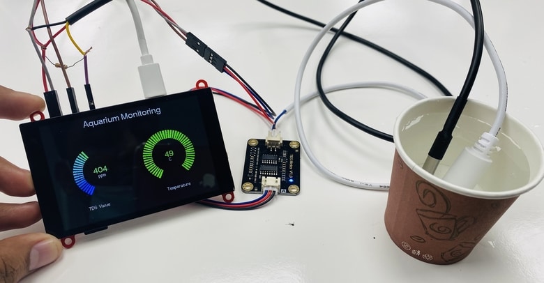
At 21°C temperature, the TDS value was 344ppm but at 49°C, the TDS value reached to 404ppm.
For an aquarium, the temperature good range is 76° to 80°F (25° to 27°C). The 400PPM~450PPM TDS in the water is good for most freshwater fish living.

Video Tutorial & Guide

 & Live Dashboard")


4 Comments
After upload the code and rts pin for hard reseting the TFT display, the display widget is not show in the display
Display is totally blank (white shown in color) no any thing is shown
Can you please solve this issue
How can this be implemented into a reef aquarium ? as the tds is much higher than this example
Un projecto increible