

Overview
In this post, we will learn about the interfacing of the Quectel L80 GPS Module with Arduino. The L80 GPS Module from Quectel is the tiny, low cost and low-power-consuming GPS Module available in the market. The L80 GPS module with an embedded patch antenna and low-noise amplifier (LNA) brings the high performance of the positioning system in industrial applications.
It can achieve the industry’s highest level of sensitivity, accuracy, and TTFF with the lowest power consumption in a small-footprint leadless package. It acquires and tracks satellites in the shortest time even at the indoor signal level. Compared to NEO-6M GPS Module and RYS8830 GPS/GNSS Receiver, this module has the best performance.
Hence in this project, we will interface Quectel L80 GPS Module with Arduino & make our own GPS Receiver. The L80 GPS Module can give the value of Latitude, Longitude, Speed, Altitude, Date, and Time once it is synchronized with the satellite. First, we will hook up the L80 GPS with Arduino Nano Board and display the GPS parameters on Serial Monitor. Then we will use a 16×2 LCD Display to display the value of Latitude, Longitude, Speed, Altitude, Date, and Time.
Bill of Materials
You need to purchase the following components for building this project.
| S.N. | Components | Quantity | Purchase Links |
|---|---|---|---|
| 1 | Arduino Nano Board | 1 | Amazon | AliExpress |
| 2 | Quectel L80 GPS Module | 1 | Amazon | AliExpress |
| 3 | 16x2 LCD Display | 1 | Amazon | AliExpress |
| 4 | Potentiometer | 1 | Amazon | AliExpress |
| 5 | Jumper Wires | 20 | Amazon | AliExpress |
| 6 | Breadboard | 1 | Amazon | AliExpress |
Quectel L80 GPS Module

The L80 is an ideal solution for wearable fitness devices due to its ultra-compact design and low power demands. Its Low Power feature enables GPS connectivity at around half the power consumption of normal mode while in static receiving mode. Combined with its precision and high sensitivity, this makes the L80 suitable also for a broad range of IoT applications such as portable devices, automotive, personal tracking, security, and industrial PDAs.

The L80 has a patch antenna on top measuring 16.0mm × 16.0mm × 6.45mm, with 66 acquisition channels and 22 tracking channels. It acquires and tracks satellites in the shortest time even at the indoor signal level. The module operates at 2.8V~4.3V with a typical power consumption of 20mA and in Standby mode power consumption is around 1.0mA.
Key Features
1. Power Consumption: Acquisition 25mA, Tracking 20mA, Standby 1.0mA, Backup: 7uA
2. Receiver Type: GPS L1 1575.42MHz C/A Code, 66 search channels, 22 simultaneous tracking channels
3. Sensitivity: Acquisition -148dBm, Re-acquisition -160dBm, Tracking -165dBm
4. Power Supply: 2.8V~4.3V
5. Update Rate: Up to 10Hz, 1Hz by default
6. Accuracy of 1PPS Signal: Typical accuracy: +/-10ns, Time pulse width 100ms
7. Acceleration Accuracy: Without aid 0.1m/s2
8. Dynamic Performance: Maximum altitude 18000m, Maximum velocity 515m/s, Acceleration 4G
9. UART Port: TXD1 & RXD1 Supports baud rate from 4800bps to 115200bps, 9600bps by default
10. Velocity Accuracy: 0.1m/s
11. Working Temperature Range: -40~85 C
12. Embedded patch antenna
13. Built-in LNA for better sensitivity
L80 Pinout

The Quectel L80 GPS Module has 12 pins as shown in the image above. The function of each pin is defined below.
| S.N. | Pin Name | Function |
|---|---|---|
| 1 | RXD1 | UART Receiver |
| 2 | TXD1 | UART Transmitter |
| 3 | GND | Ground Logic |
| 4 | VCC | 2.8V~4.3V Supply, Typically 3.3V |
| 5 | V_BCKP | Backup power/Supply power for RTC |
| 6 | 1PPS | One pulse per second, Synchronized at the rising edge, the pulse width is 100ms |
| 7 | TIMER | Open-drain output signal used to control GPS module main power on/off |
| 8 | AADET_N | Active antenna detection |
| 9 | NC | Not Connected |
| 10 | RESET | System reset |
| 11 | EX_ANT | External active antenna RF input |
| 12 | GND | Ground Logic |
To learn more about this module you can refer to L80 Datasheet
Soldering Header Pins to L80 Module
The L80 is a tiny SMD-type Module that doesn’t have any male/female header pins for testing. So you can use the male header pin with 2.54 spacing and solder them on the L80 PCB from the bottom.

Once, you solder all the 12 Pins on the L80 Module, the Module becomes breadboard friendly. You can now insert the module on the breadboard easily.

Interfacing Quectel L80 GPS Module with Arduino
Now let us interface L80 GPS Module with Arduino. You can connect the L80 GPS Module with Arduino Nano as per the circuit diagram below.

The connection is fairly simple. Connect the VCC/GND for the power supply & do not supply more than 3.3V. Similarly, connect the VCC backup (V_BCKP) with VCC or to an external battery. It won’t work if this pin is not powered.
Connect the RX/TX of L80 to the D2/D3 of the Arduino. This is for Serial Communication using Software Serial.

Source Code/Program & Testing
The best part about the L80 GPS Module is, it supports Tiny GPS++ Library. Download the library and add it to the library folder.
Copy the following L80 Arduino Code and upload it to the Arduino Board.
|
1 2 3 4 5 6 7 8 9 10 11 12 13 14 15 16 17 18 19 20 21 22 23 24 25 26 27 28 29 30 31 32 33 34 35 36 37 38 39 40 41 42 43 44 45 46 |
#include <TinyGPS++.h> #include <SoftwareSerial.h> #define rxGPS 3 #define txGPS 2 long lat, lon; SoftwareSerial gpsSerial(rxGPS, txGPS); TinyGPSPlus gps; void setup() { Serial.begin(9600); // connect serial gpsSerial.begin(9600); // connect gps sensor } void loop() { while (gpsSerial.available()) // check for gps data { if (gps.encode(gpsSerial.read())) // encode gps data { Serial.print("SATS: "); Serial.println(gps.satellites.value()); Serial.print("LAT: "); Serial.println(gps.location.lat(), 6); Serial.print("LONG: "); Serial.println(gps.location.lng(), 6); Serial.print("ALT: "); Serial.println(gps.altitude.meters()); Serial.print("SPEED: "); Serial.println(gps.speed.mps()); Serial.print("Date: "); Serial.print(gps.date.day()); Serial.print("/"); Serial.print(gps.date.month()); Serial.print("/"); Serial.println(gps.date.year()); Serial.print("Hour: "); Serial.print(gps.time.hour()); Serial.print(":"); Serial.print(gps.time.minute()); Serial.print(":"); Serial.println(gps.time.second()); Serial.println("---------------------------"); delay(4000); } } } |
After uploading the code, open the Serial Monitor. Initially, it displays the wrong data as GPS Module is not synchronized with the Satellite.

For the first time, it might take 2-3 minutes to retrieve data. Next time onwards it retrieves location very quickly. In the Serial Monitor, you will be able to see the Latitude, Longitude, Altitude, Speed, Time, and Date.

L80 Arduino GPS Receiver with LCD Display
Instead of displaying the data on Serial Monitor, let us integrate 16X2 LCD Display to the above circuit as shown in the image below. So, let us interface Quectel L80 GPS Module with Arduino.

The LCD works at 5V. To connect the rs, en, d4, d5, d6, d7 pins of LCD, you can choose any Arduino Pin and define them in the code. For example, we use A0, A1, A2, A3, A4, A5 Pin.

Source Code/Program & Testing
Here is a code for Interfacing Quectel L80 GPS Module with Arduino and 16×2 LCD Display. Copy the code and upload it to the Arduino Board.
|
1 2 3 4 5 6 7 8 9 10 11 12 13 14 15 16 17 18 19 20 21 22 23 24 25 26 27 28 29 30 31 32 33 34 35 36 37 38 39 40 41 42 43 44 45 46 47 48 49 50 51 52 53 54 55 56 57 58 59 60 61 62 63 64 65 66 67 68 69 70 71 72 73 74 75 76 77 78 79 80 81 82 83 84 85 86 87 88 89 90 91 92 93 94 |
#include <TinyGPS++.h> #include <SoftwareSerial.h> #include <LiquidCrystal.h> // include the library code const int rs = A0, en = A1, d4 = A2, d5 = A3, d6 = A4, d7 = A5; LiquidCrystal lcd(rs, en, d4, d5, d6, d7); #define txGPS 2 #define rxGPS 3 long lat, lon; //int counter = 0; SoftwareSerial gpsSerial(rxGPS, txGPS); TinyGPSPlus gps; void setup() { Serial.begin(9600); // connect serial gpsSerial.begin(9600); // connect gps sensor lcd.begin(16, 2); } void loop() { while (gpsSerial.available()) // check for gps data { if (gps.encode(gpsSerial.read())) // encode gps data { Serial.print("SATS: "); Serial.println(gps.satellites.value()); Serial.print("LAT: "); Serial.println(gps.location.lat(), 6); Serial.print("LONG: "); Serial.println(gps.location.lng(), 6); Serial.print("ALT: "); Serial.println(gps.altitude.meters()); Serial.print("SPEED: "); Serial.println(gps.speed.mps()); Serial.print("Date: "); Serial.print(gps.date.day()); Serial.print("/"); Serial.print(gps.date.month()); Serial.print("/"); Serial.println(gps.date.year()); Serial.print("Hour: "); Serial.print(gps.time.hour()); Serial.print(":"); Serial.print(gps.time.minute()); Serial.print(":"); Serial.println(gps.time.second()); Serial.println("---------------------------"); lcd.setCursor(0, 0); lcd.print("LAT: "); lcd.print(gps.location.lat(), 6); lcd.setCursor(0, 1); lcd.print("LON: "); lcd.print(gps.location.lng(), 6); delay(2000); lcd.clear(); lcd.setCursor(0, 0); lcd.print("ALT: "); lcd.print(gps.altitude.meters()); lcd.print(" m"); lcd.setCursor(0, 1); lcd.print("SPD: "); lcd.print(gps.speed.mps()); lcd.print(" mps"); delay(2000); lcd.clear(); lcd.setCursor(0, 0); lcd.print("Date: "); lcd.print(gps.date.day()); lcd.print("/"); lcd.print(gps.date.month()); lcd.print("/"); lcd.print(gps.date.year()); lcd.setCursor(0, 1); lcd.print("Time: "); lcd.print(gps.time.hour()); lcd.print(":"); lcd.print(gps.time.minute()); lcd.print(":"); lcd.print(gps.time.second()); delay(2000); lcd.clear(); } } } |
After uploading the code, wait for some time. When the GPS Module synchronizes with the satellite it will display the Latitude and Longitude Value on LCD Display.

Similarly, it will also display the local time and date on the LCD Screen.

And finally, it will also display the Altitude above sea level and the velocity with which the object is moving.

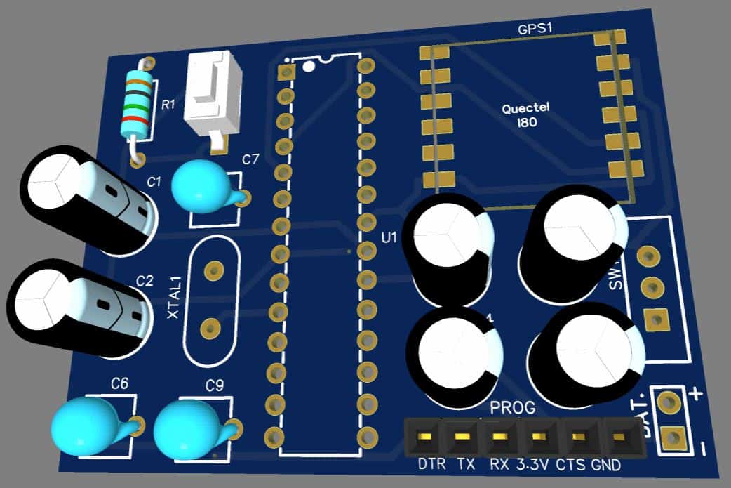
Battery Powered Portable GPS Receiver
Since the L80 GPS Module operates at 3.3V, we can easily make a Battery Powered GPS Receiver. The circuit can be powered via 3.7V Lithium-Ion Battery.
The circuit below is a simple circuit made using Atmega328 Microcontroller and only necessary components. You can assemble the components on a breadboard or use a PCB to assemble the component.

The circuit has all the necessary components to run the Atmega328 microcontroller with Arduino Code. You can use a reset button to reset the entire circuit. A switch is used for turning ON/OFF the device. Similarly, there is a programming pin that is used to program the Atmega328 Microcontroller using the FTDI Module.
You can directly connect a 3.7V Lithium-Ion or a Lithium Polymer Battery to power the device. To read the output data you connect the device to your phone using the USB-to-TTL Module. Then open the Serial Monitor on Android/iPhone and there you can read the GPS Data.
Project PCB Gerber File & PCB Ordering Online
If you don’t want to assemble the circuit on a breadboard and you want PCB for the project, then here is the PCB for you. I used EasyEDA to design the PCB. The PCB Board for Interfacing L80 GPS Module Arduino Microcontroller looks something like below.

The Gerber File for the PCB is given below. You can simply download the Gerber File and order the PCB from ALLPCB at 1$ only.
You can use this Gerber file to order high quality PCB for this project. To do that visit the ALLPCB official website by clicking here: https://www.allpcb.com/.

You can now upload the Gerber File by choosing the Quote Now option. From these options, you can choose the Material Type, Dimensions, Quantity, Thickness, Solder Mask Color and other required parameters.

After filling all details, select your country and shipping method. Finally you can place the order.
You can assemble the components on the PCB Board.

")


