

Overview
In this tutorial, we will learn how we can use GSM Module with Arduino for communication with Google Firebase or Thingspeak Server. For this we will use an Arduino IoT Box designed using SIM800C and Atmega328 Microcontroller. The Arduino IoT box from Graylogix is a combination of GSM and Arduino for Battery Powered IoT Applications.
We will use the combination of GSM & Arduino to communicate with Firebase or Thingspeak. The DHT11 sensor which measures temperature and Humidity can be interfaced with Arduino easily. Initially, we will send the DHT11 Sensor Data to Thingspeak Server. After that, we will use Google Firebase to receive or monitor the data remotely.
Bill of Materials
You can purchase the required components from the following links.
| S.N. | Components | Quantity | Purchase Links |
|---|---|---|---|
| 1 | Arduino IoT Box | 1 | Graylogix |
| 3 | DHT11 Sensor | 1 | Amazon | AliExpress |
| 2 | Connecting Wires | 1 | Amazon | AliExpress |
About Arduino IoT Box

The Arduino IoT Box is an Open Source Hardware for Arduino + GSM with Battery and I/O Ports. Due to the small size and properly assembled PCB, it is best Suitable for IoT Projects.

Inside the Box, there is a PCB board that has SIM800C GSM Module and an Atmega328 Microcontroller with Arduino Bootloader. The box is powered via a 3.7V, 1000mAh Lithium-Ion Battery. To charge the battery the box has TP4056 Battery Management System IC. The battery can be charged micro-USB Cable by plugging it into the Micro-USB Port. The same USB port is also used to dump the code.
The box uses an external GSM Antenna which should be connected before powering the device. You can insert the nano Sim card in the dedicated SIM slot. Remember, SIM800 is a 2G Module and only supports 2G SIM. Dedicated I/O pins on board can be used to interface external sensors and other I/O devices conveniently by soldering berg strips on board. External interfacing can also be done using AD0 to AD3 (pulled high internally) which are connected internally to Arduino nano and one of the pins of the white RMZ is connected to the ground.
LED Indications
There are 5 different LEDs on the box to indicate the power, Network, Battery Charging, Battery Full, etc.

Orange LED indicates charging of the battery through the USB cable and Green LED indicates charging completed and the battery is full. COM port LED is lit at the time of dumping the code or data transmission between the device and the computer.
Blue LED Indicates the status of the GSM network,
1 sec Blinking = in N/W Search Mode.
3 Sec Blinking = Network Acquired Successfully.
½ Sec Blinking = connected to GPRS.
Default Connection
TX of GSM SIM800C is connected to D8 of Arduino Nano
RX of GSM SIM800C is connected to D7 of Arduino Nano
Red colour TEST LED is connected to D9 of Arduino Nano.
Aplications
You can use the Arduino IoT Box for Arduino Projects, IOT Projects, Realtime Projects, GSM based server communication, Data logger, Temperature Monitoring System, Sensor Data Acquisition, SMS Triggering etc.
Sending Sensor Data to Thingspeak Server
First we need to connect a DHT11 Sensor to Arduino IoT Box. You need to solder some male header pins on the PCB or just directly connect the DHT11 Sensor.

Connect the GND and VCC Pin of DHT11 Sensor to Arduino GND & 4V Pin. Similarly, connect the output pin to the D3 of the Arduino. You can also refer to the previous article to Send Sensor Data to Thingspeak.
Setting up Thingspeak
ThingSpeak provides very good tool for IoT based projects. By using ThingSpeak site, we can monitor our data and control our system over the Internet, using the Channels and web pages provided by ThingSpeak. So first you need to sign up for ThingSpeak. So visit https://thingspeak.com and create an account.

Then create a new channel and set up what you want. The tutorial in the video below. Follow the video for more clarifications.

Then create the API keys. This key is required for programming modifications and setting your data.

Now click on channels so that you can see the online data streaming
Source Code/Program
The source code/program to Send GSM SIM800/900 GPRS Data to Thingspeak with Arduino is given below. You can simply copy the code and upload to the Arduino Board.
From the code, change the APN. For example the APN for Airtel is airtelgprs.com. You can check your SIM APN from your google or cellular provider.
|
1 2 3 4 5 6 7 8 9 10 11 12 13 14 15 16 17 18 19 20 21 22 23 24 25 26 27 28 29 30 31 32 33 34 35 36 37 38 39 40 41 42 43 44 45 46 47 48 49 50 51 52 53 54 55 56 57 58 59 60 61 62 63 64 65 66 67 68 69 70 71 72 73 74 75 76 77 78 79 80 81 82 83 84 85 86 87 88 89 90 91 92 93 94 95 96 97 98 99 100 101 102 103 104 105 106 107 108 109 110 111 112 113 114 |
#include <SoftwareSerial.h> #include <DHT.h> #define DHTPIN 3 DHT dht(DHTPIN, DHT11); SoftwareSerial gprsSerial(8, 7); #include <String.h> void setup() { gprsSerial.begin(9600); // the GPRS baud rate Serial.begin(9600); dht.begin(); delay(1000); } void loop() { float h = dht.readHumidity(); float t = dht.readTemperature(); delay(100); Serial.print("Temperature = "); Serial.print(t); Serial.println(" °C"); Serial.print("Humidity = "); Serial.print(h); Serial.println(" %"); if (gprsSerial.available()) Serial.write(gprsSerial.read()); gprsSerial.println("AT"); delay(1000); gprsSerial.println("AT+CPIN?"); delay(1000); gprsSerial.println("AT+CREG?"); delay(1000); gprsSerial.println("AT+CGATT?"); delay(1000); gprsSerial.println("AT+CIPSHUT"); delay(1000); gprsSerial.println("AT+CIPSTATUS"); delay(2000); gprsSerial.println("AT+CIPMUX=0"); delay(2000); ShowSerialData(); gprsSerial.println("AT+CSTT=\"airtelgprs.com\"");//start task and setting the APN, delay(1000); ShowSerialData(); gprsSerial.println("AT+CIICR");//bring up wireless connection delay(3000); ShowSerialData(); gprsSerial.println("AT+CIFSR");//get local IP adress delay(2000); ShowSerialData(); gprsSerial.println("AT+CIPSPRT=0"); delay(3000); ShowSerialData(); gprsSerial.println("AT+CIPSTART=\"TCP\",\"api.thingspeak.com\",\"80\"");//start up the connection delay(6000); ShowSerialData(); gprsSerial.println("AT+CIPSEND");//begin send data to remote server delay(4000); ShowSerialData(); String str = "GET " + String(t) +"&field2="+String(h); Serial.println(str); gprsSerial.println(str);//begin send data to remote server delay(4000); ShowSerialData(); gprsSerial.println((char)26);//sending delay(5000);//waitting for reply, important! the time is base on the condition of internet gprsSerial.println(); ShowSerialData(); gprsSerial.println("AT+CIPSHUT");//close the connection delay(100); ShowSerialData(); } void ShowSerialData() { while (gprsSerial.available() != 0) Serial.write(gprsSerial.read()); delay(5000); } |
Test/Results
After uploading the code, the GSM Module will try connecting to the Cellular Network. Then it will establish the connection with Thingspeak Server. You can open the Serial Monitor to see all the steps.
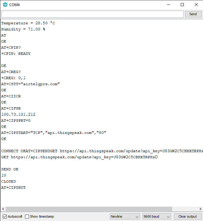
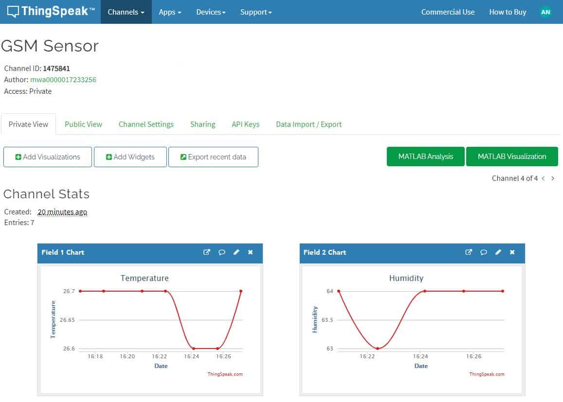
Similarly go to the Private view of Thingspeak Server. You will see the temperature and Humidity data getting uploaded after 30 seconds.
Sending Sensor Data to Firebase using GSM/Arduino
Now let us see how we can send the DHT11 Sensor Data to Google Firebase using SIM800C GSM Module and Arduino. First we need to setup the Google Firebase.
In earlier post, we learned to Send Sensor Data to Firebase with ESP8266. You can follow basic Google Firebase Setup tutorial to setup the firebase first.
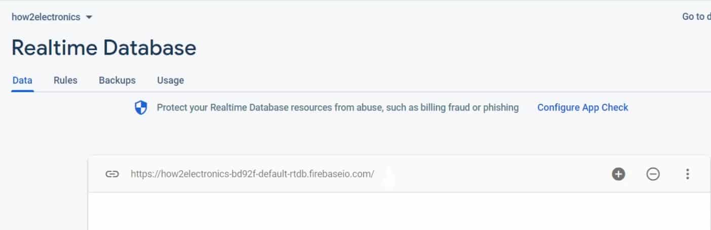
We need the Firebase Host and the Authentication to connect the GSM to Firebase for communication.
You can get the Firebase Host from the Realtime Database.
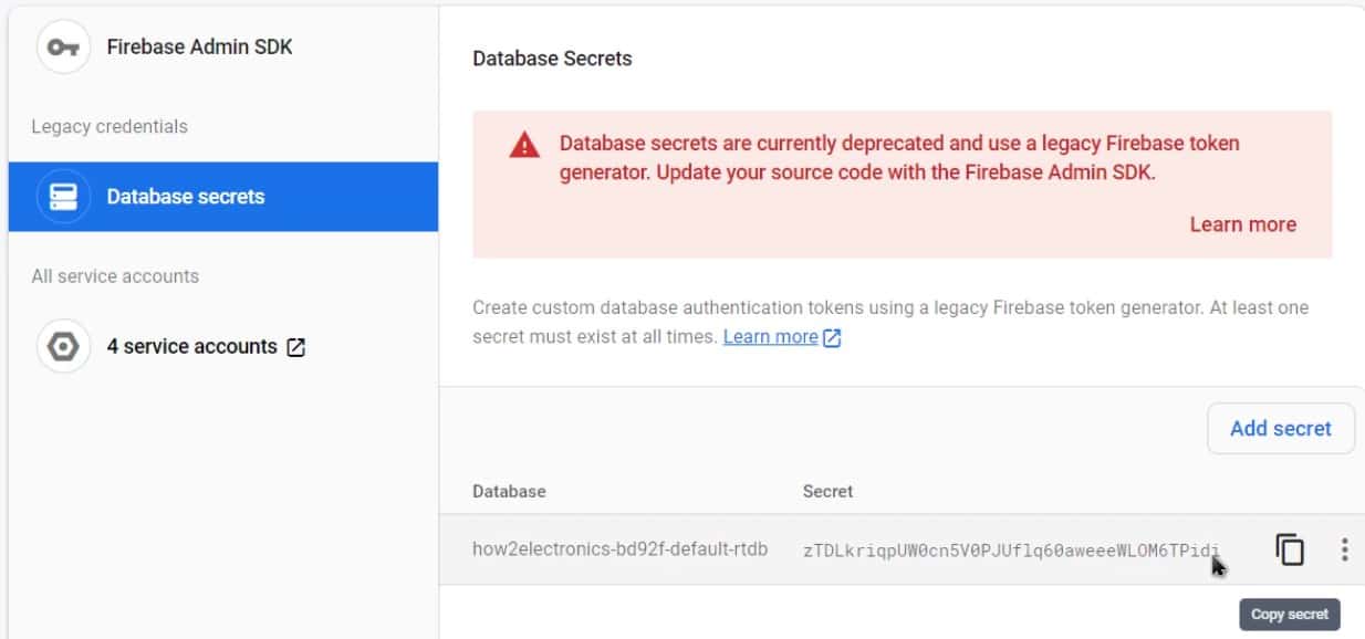
You can copy the Authentication Token from Database Secrets.
Source Code for Arduino GSM Firebase
Follwing code can help to communicate the GSM & Arduino with Google Firebase. But the code requires TinyGsmClient Library as well as ArduinoHttpClient Library. First download these libraries and add it to the Arduino Library Folder.
|
1 2 |
const char FIREBASE_HOST[] = "********************************************"; const String FIREBASE_AUTH = "********************************************"; |
Change the Firebase Host and the Authentication Token from the above lines.
|
1 |
char apn[] = "www";//airtel ->"airtelgprs.com" |
Change for SIM or Service Provider APN from the above line.
Now you can copy the below code and upload it to the Arduino Board.
|
1 2 3 4 5 6 7 8 9 10 11 12 13 14 15 16 17 18 19 20 21 22 23 24 25 26 27 28 29 30 31 32 33 34 35 36 37 38 39 40 41 42 43 44 45 46 47 48 49 50 51 52 53 54 55 56 57 58 59 60 61 62 63 64 65 66 67 68 69 70 71 72 73 74 75 76 77 78 79 80 81 82 83 84 85 86 87 88 89 90 91 92 93 94 95 96 97 98 99 100 101 102 103 104 105 106 107 108 109 110 111 112 113 114 115 116 117 118 119 120 121 122 123 124 125 126 127 128 129 130 131 132 133 134 135 136 137 138 139 140 141 142 143 144 145 146 147 |
#define TINY_GSM_MODEM_SIM800 #define TINY_GSM_RX_BUFFER 256 #include <TinyGsmClient.h> //https://github.com/vshymanskyy/TinyGSM #include <ArduinoHttpClient.h> //https://github.com/arduino-libraries/ArduinoHttpClient #include <DHT.h> #include <SoftwareSerial.h> #define rxPin 7 #define txPin 8 SoftwareSerial sim800(txPin, rxPin); #define DHTPIN 3 DHT dht(DHTPIN, DHT11); const char FIREBASE_HOST[] = "***************************************"; const String FIREBASE_AUTH = "***************************************"; const String FIREBASE_PATH = "/"; const int SSL_PORT = 443; char apn[] = "www";//airtel ->"airtelgprs.com" char user[] = ""; char pass[] = ""; TinyGsm modem(sim800); TinyGsmClientSecure gsm_client_secure_modem(modem, 0); HttpClient http_client = HttpClient(gsm_client_secure_modem, FIREBASE_HOST, SSL_PORT); unsigned long previousMillis = 0; void setup() { Serial.begin(115200); dht.begin(); Serial.println("device serial initialize"); sim800.begin(9600); Serial.println("SIM800L serial initialize"); Serial.println("Initializing modem..."); modem.restart(); String modemInfo = modem.getModemInfo(); Serial.print("Modem: "); Serial.println(modemInfo); http_client.setHttpResponseTimeout(10 * 1000); //^0 secs timeout } void loop() { Serial.print(F("Connecting to ")); Serial.print(apn); if (!modem.gprsConnect(apn, user, pass)) { Serial.println(" fail"); delay(1000); return; } Serial.println(" OK"); http_client.connect(FIREBASE_HOST, SSL_PORT); while (true) { if (!http_client.connected()) { Serial.println(); http_client.stop();// Shutdown Serial.println("HTTP not connect"); break; } else { dht_loop(); } } } void PostToFirebase(const char* method, const String & path , const String & data, HttpClient* http) { String response; int statusCode = 0; http->connectionKeepAlive(); // Currently, this is needed for HTTPS String url; if (path[0] != '/') { url = "/"; } url += path + ".json"; url += "?auth=" + FIREBASE_AUTH; Serial.print("POST:"); Serial.println(url); Serial.print("Data:"); Serial.println(data); String contentType = "application/json"; http->put(url, contentType, data); statusCode = http->responseStatusCode(); Serial.print("Status code: "); Serial.println(statusCode); response = http->responseBody(); Serial.print("Response: "); Serial.println(response); if (!http->connected()) { Serial.println(); http->stop();// Shutdown Serial.println("HTTP POST disconnected"); } } void dht_loop() { String h = String(dht.readHumidity(), 2); String t = String(dht.readTemperature(), 2); delay(100); Serial.print("Temperature = "); Serial.print(t); Serial.println(" °C"); Serial.print("Humidity = "); Serial.print(h); Serial.println(" %"); String Data = "{"; Data += "\"temp\":" + t + ","; Data += "\"humid\":" + h + ""; Data += "}"; PostToFirebase("PATCH", FIREBASE_PATH, Data, &http_client); } |
Test/Results
After uploading the code, the Nodemcu will connect to the Wifi Network. Now you can open the serial monitor, it will show the temperature and humidity reading.

When the temperature and humidity data is displayed on Serial Monitor at the same time, the data is sent to Google Firebase Database. You can just open the google Firebase console window and check the real-time entry of the data.
Video Tutorial/Guide
To learn more about the Arduino IoT Box, follow the video below.

 & Live Dashboard")


6 Comments
Need help for A9G pudding module !
Hello I want to control led via firebase with arduino gsm module
Have you done anything similar using firestore?
can you please share the PCB files ?
Can we use the same model to send latitude and longitude data instead of temperature and humidity ? If so, how pls ?
did you get any reply?