

Introduction
This guide is about 12-bit DAC Usage in Arduino UNO R4 Minima Microcontroller Board.
The Arduino R4 Minima is a versatile microcontroller board designed for both beginners and experienced users. One of its key features is the 12-bit Digital-to-Analog Converter (DAC). DACs are important in many electronic systems because they change digital values back into analog signals. These analog signals can then interact with other parts of the system or be measured.
Most standard Arduino boards don’t have a built-in DAC. Therefore we have to use external DACs like MCP4725. However, the R4 Minima version comes with a 12-bit DAC. This means it can produce 4,096 different analog values, giving users more control and precision in their projects.
In this guide, we’ll show you how to use the 12-bit DAC on the Arduino R4 Minima. We’ll talk about its benefits and provide some useful tips. Additionally, we will explore the generation of various waveforms using the DAC such as Sine, Square, and Sawtooth waveforms.
- Read this first: Arduino UNO R4 Minima Getting Started Guide
- ADC Usage Guide: 14-Bit ADC Usage in Arduino UNO R4 Minima
- Recommended R4 Minima Kit: SunFounder Ultimate Kit
DAC Pin in Arduino UNO R4 Minima Board
The Arduino UNO R4 Minima has a built-in DAC (Digital-to-Analog Converter) with up to 12-bit resolution. This DAC is attached to the A0 analog pin. It can act as a genuine analog output pin, making it more versatile than PWM pins.

By default, the DAC pin has a write resolution of 8 bits but can be changed to 10-Bit or 12-Bit in coding part.
Features of DAC in Arduino UNO R4 Minima Board
- Enhanced Output Precision: The R4 Minima board is equipped with a 12-bit DAC, a step up from boards that might not have a built-in DAC. This allows it to generate analog output with greater precision, offering 4,096 discrete output values.
- Variable Output Range: The DAC allows users to select between different output voltage ranges, providing flexibility in generating the desired analog signal.
- High-Speed Signal Generation: The DAC in the R4 Minima is designed for rapid signal generation, making it suitable for applications that require real-time analog signal output.
- Noise Filtering Capabilities: The DAC comes with features that filter out noise, ensuring that the generated analog signal is clean and accurate.
- Multiple Waveform Generation: The DAC can produce various waveforms, such as sine, square, and sawtooth. This versatility is beneficial for applications ranging from audio signal generation to test signal outputs.
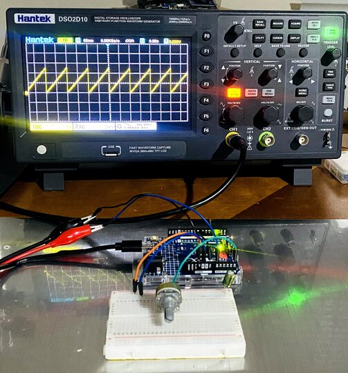
Hardware Setup for DAC Usage
Lets setup the Arduino UNO R4 Minima Board to generate discrete output voltages from 0 to 5 volts using the DAC Pin. The DAC Pins can also be used to generate waveforms which will be demonstrated here.

Connection Steps:
- Potentiometer Ground: Connect one of the outer pins of the potentiometer to the Arduino’s GND pin.
- Potentiometer Voltage: Connect the other outer pin to the Arduino’s 5V pin.
- Signal to A5: Connect the potentiometer’s middle pin (wiper) to the A5 pin on the Arduino.

Ensure all connections are secure. Now, the potentiometer can control the frequency of the waveforms. The output from A0 pin and GND is directly connected to the Oscilloscope.
Sine Wave Generator
The first application of DAC of Arduino UNO R4 Minima is generation of Sine Waveform. Generating a sine wave using is a great way to produce a smooth analog waveform.
Here is the code to generate the waveform. Copy the code and paste it on your Arduino IDE.
|
1 2 3 4 5 6 7 8 9 10 11 12 13 14 15 16 17 18 19 20 21 22 23 |
#include "analogWave.h" // Include the library for analog waveform generation analogWave wave(DAC); // Create an instance of the analogWave class, using the DAC pin int freq = 10; // in hertz, change accordingly void setup() { Serial.begin(115200); // Initialize serial communication at a baud rate of 115200 wave.sine(freq); // Generate a sine wave with the initial frequency } void loop() { // Read an analog value from pin A5 and map it to a frequency range freq = map(analogRead(A5), 0, 1024, 0, 10000); // Print the updated frequency to the serial monitor Serial.println("Frequency is now " + String(freq) + " hz"); wave.freq(freq); // Set the frequency of the waveform generator to the updated value delay(1000); // Delay for one second before repeating } |
After uploading the code to the Arduino Board, setup the oscilloscope to see the waveform.
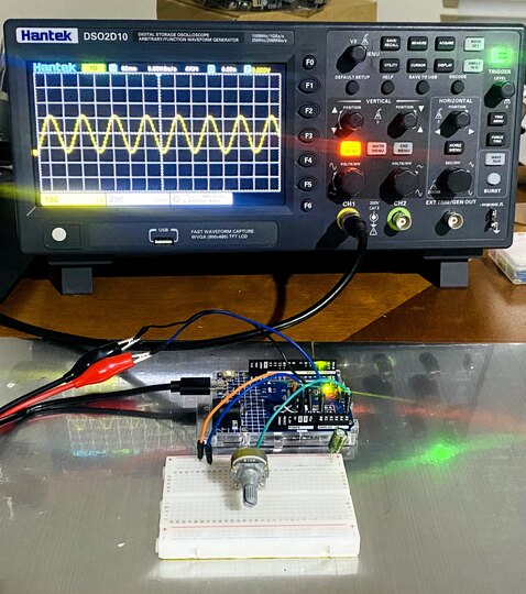
The generated waveform looks similar to sine wave.
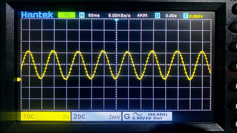
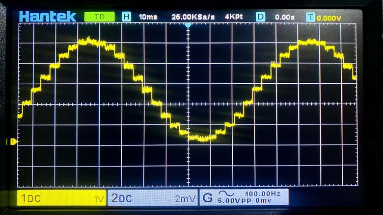
When the scaling is done, the quantization level can be clearly observed.
Square Wave Generator
After generating the sine wave, the Arduino UNO R4 Minima DAC Pin can also be used to generate the square waveform. Generating a square wave is a straightforward task. The DAC will alternate between two voltage levels to create the square wave.
Here is the code for this.
|
1 2 3 4 5 6 7 8 9 10 11 12 13 14 15 16 17 18 19 20 21 22 23 24 25 26 27 28 |
#include "analogWave.h" // Include the library for analog waveform generation analogWave wave(DAC); // Create an instance of the analogWave class, using the DAC pin int freq = 10; // in hertz, change accordingly void setup() { Serial.begin(115200); // Initialize serial communication at a baud rate of 115200 wave.square(freq); // Generate a square wave with the initial frequency wave.begin(freq); // Begin the waveform generation wave.start(); // Start the waveform generation } void loop() { // Read an analog value from pin A5 and map it to a frequency range freq = map(analogRead(A5), 0, 1023, 0, 10000); // Print the updated frequency to the serial monitor Serial.print("Frequency is now "); Serial.print(freq); Serial.println(" hz"); wave.freq(freq); // Set the frequency of the waveform generator to the updated value delay(1000); // Delay for one second before repeating } |
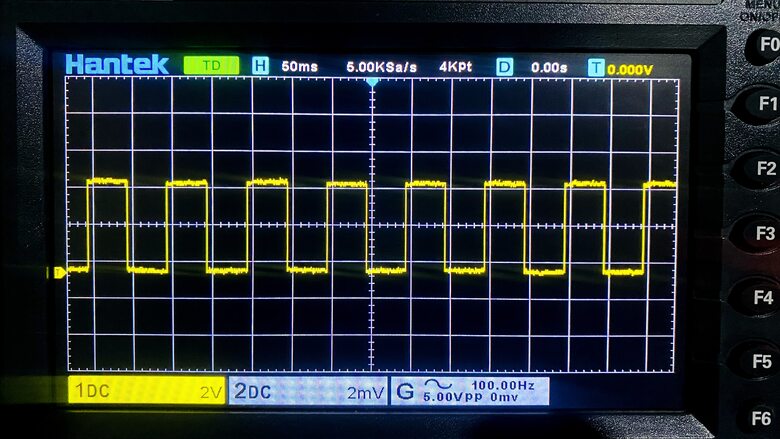
After uploading the above code the Oscilloscope can be adjusted to observe the square wave.
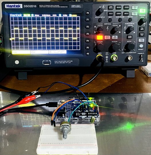
When the waveform is observed closely, the alternation between the wave is a straight line.
Sawtooth Wave Generator
Generating a Sawtooth wave using Arduino UNO R4 Minimo involves incrementing and decrementing the DAC output in a loop to create a linear rise and fall in voltage.
Here is the code for this.
|
1 2 3 4 5 6 7 8 9 10 11 12 13 14 15 16 17 18 19 20 21 22 23 24 25 26 27 28 |
#include "analogWave.h" // Include the library for analog waveform generation analogWave wave(DAC); // Create an instance of the analogWave class, using the DAC pin int freq = 10; // in hertz, change accordingly void setup() { Serial.begin(115200); // Initialize serial communication at a baud rate of 115200 wave.saw(freq); // Generate a sawtooth waveform with the initial frequency wave.begin(freq); // Begin the waveform generation wave.start(); // Start the waveform generation } void loop() { // Read an analog value from pin A5 and map it to a frequency range freq = map(analogRead(A5), 0, 1023, 0, 10000); // Print the updated frequency to the serial monitor Serial.print("Frequency is now "); Serial.print(freq); Serial.println(" hz"); wave.freq(freq); // Set the frequency of the waveform generator to the updated value delay(1000); // Delay for one second before repeating } |
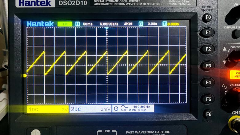
After uploading the above code, adjust the Oscilloscope settings to observe the sawtooth wave.
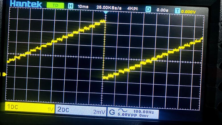
The waveform generated looks a perfect sawtooth wave.
The digital to analog conversion can only be observed when the waveform is more and more expanded.
Conclusion
Throughout our exploration, we’ve seen the versatility of the Arduino UNO R4 12-Bit DAC Pin.It has a great ability to generate a variety of analog voltages. The practical application of DAC is in generating varios waveforms like Sine, Square, and Sawtooth Waveform.

")


