

Introduction
This guide is about 14-bit ADC Usage in Arduino UNO R4 Minima Microcontroller Board.
The Arduino UNO R4 Minima is a versatile microcontroller board that offers a range of features for both beginners and experienced developers. One of its standout features is the 14-bit Analog-to-Digital Converter (ADC). ADCs are crucial components in many electronic systems, allowing for the conversion of analog signals (like those from sensors) into digital values that can be processed by microcontrollers.
Traditionally, the Arduino UNO boards come equipped with a 10-bit ADC, which provides a resolution of 1024 discrete values. However, the R4 Minima variant boasts a 14-bit ADC, offering a significantly higher resolution of 16,384 discrete values. This enhanced resolution allows for more precise readings and finer granularity, making it ideal for applications that require detailed and accurate analog signal measurements.
In this guide, we’ll show you how to use the 14-bit ADC on the Arduino UNO R4 Minima. We’ll explain its benefits and give you some helpful tips. Plus, we’ll also discuss how to use 10, 12, and 14-bit ADCs and talk about the smallest voltage difference they can detect.
- Read this first: Arduino UNO R4 Minima Getting Started Guide
- Recommended R4 Minima Kit: SunFounder Ultimate Kit
ADC Pins in Arduino UNO R4 Minima Board
The Arduino UNO R4 Minima Board, like its predecessors, comes equipped with multiple Analog Input Pins that can be used for reading analog signals. These pins are typically labeled as A0, A1, A2 and so on.

The board usually has 6 analog input pins (A0 to A5). These pins can read signals from analog sensors like temperature sensors, potentiometers, and light sensors.
Features of ADC in Arduino UNO R4 Minima Board
- Enhanced Resolution: Unlike the standard 10-bit ADC in most Arduino UNO boards, the R4 Minima variant boasts a 14-bit ADC. This means it can represent the analog input value with more precision, offering 16,384 discrete values.
- Variable Voltage Reference: Users can choose between internal or external voltage references for the ADC, allowing for more flexibility in readings.
- Increased Sampling Rate: The ADC in the R4 Minima might offer a faster sampling rate, enabling quicker analog signal readings, which is crucial for real-time applications.
- Noise Reduction Mode: Some advanced ADC features include noise reduction capabilities, ensuring more accurate and less noisy readings.
- Differential Mode: This mode allows the ADC to measure the difference between two input pins, which can be useful in specific applications where the difference in signals is of interest.
Hardware Setup for ADC Usage
To use the ADC Pin, we will use a 10K potentiometer to supply voltages between 0V-5V to the A0 pin of Arduino Board. Here is a simple connection diagram.

Connection Steps:
- Potentiometer Ground: Connect one of the outer pins of the potentiometer to the Arduino’s GND pin.
- Potentiometer Voltage: Connect the other outer pin to the Arduino’s 5V pin.
- Signal to A0: Connect the potentiometer’s middle pin (wiper) to the A0 pin on the Arduino.
Ensure all connections are secure. Now, the potentiometer is ready to provide variable voltage to the A0 pin, which can be read by the Arduino’s ADC.
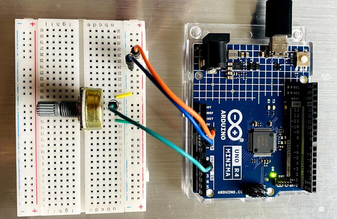
You can connect the potentiometer to the Arduino Board using the jumper wires on a breadboard.
Reading 10-Bit ADC Value & Voltage
Here is the basic code to read 10-Bit ADC Value and Voltage. In the code, the ADC resolution is set to 10 bits using the line: analogReadResolution(10);
A 10-bit ADC means that the analog value can be represented using 1024 discrete values, ranging from 0 to 1023. When you read an analog input using the analogRead() function, it returns a value between 0 and 1023.
The voltage at the analog pin is calculated using the formula:
float voltage = (reading/1023.0)*5;
Use the ADC Calculator to calculate the ADC Value.
Copy this code and upload it to the Arduino UNO R4 Board.
|
1 2 3 4 5 6 7 8 9 10 11 12 13 14 15 16 17 18 19 20 21 22 23 |
int analogpin = A0; void setup() { analogReadResolution(10); //change to 10-bit resolution Serial.begin(9600); } void loop() { int reading = analogRead(analogpin); float voltage = (reading/1023.0)*5; Serial.print("Analog Value: "); Serial.println(reading); Serial.print("Voltage: "); Serial.print(voltage,6); Serial.println("V"); Serial.println(); delay(100); } |
Open the Serial Monitor to observe the ADC Value and Voltage.
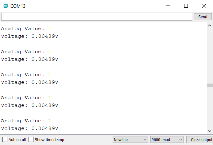
At ADC Value of 1, the voltage measured was 0.00489V which is 4.89mV. Therefore the minimum voltage that Arduino UNO R4 measures is 4.89mV.
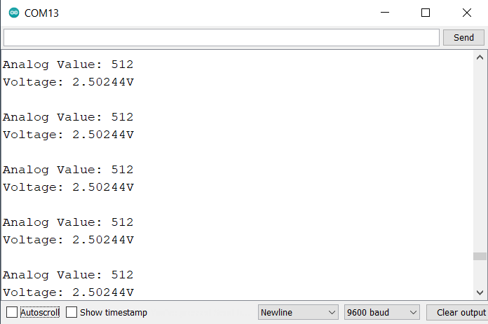
At 2.5V the the measured ADC Value is 512.

At 5V the the measured ADC Value is 1023.
Reading 12-Bit ADC Value & Voltage
Here is the basic code to read 12-bit ADC Value and Voltage. In the code, the ADC resolution is set to 12 bits using the line: analogReadResolution(12);
A 12-bit ADC means that the analog value can be represented using 4096 discrete values, ranging from 0 to 4095. When you read an analog input using the analogRead() function, it returns a value between 0 and 4095.
The voltage at the analog pin is calculated using the formula: float voltage = (reading/4095.0)*5;
Copy this code and upload it to the Arduino UNO R4 Board.
|
1 2 3 4 5 6 7 8 9 10 11 12 13 14 15 16 17 18 19 20 21 22 23 |
int analogpin = A0; void setup() { analogReadResolution(12); //change to 12-bit resolution Serial.begin(9600); } void loop() { int reading = analogRead(analogpin); float voltage = (reading/4095.0)*5; Serial.print("Analog Value: "); Serial.println(reading); Serial.print("Voltage: "); Serial.print(voltage,6); Serial.println("V"); Serial.println(); delay(100); } |
Open the Serial Monitor to observe the ADC Value and Voltage.
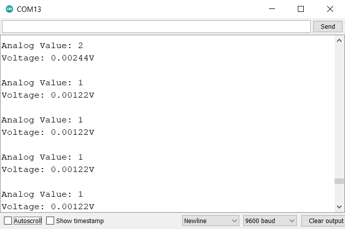
At ADC Value of 1, the voltage measured was 0.00122V which is 1.22mV. Therefore, the minimum voltage that Arduino UNO R4 measures is 1.22mV.
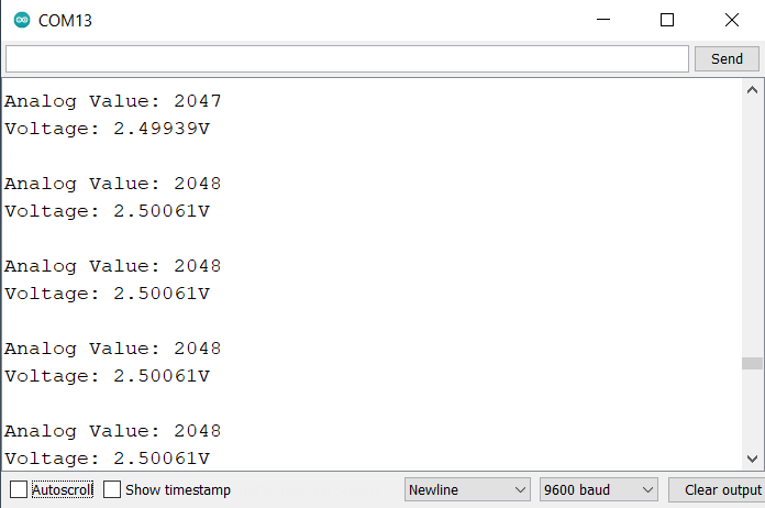
At 2.5V, the measured ADC Value is 2048.
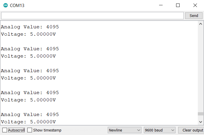
At 5V, the measured ADC Value is 4095.
Reading 14-Bit ADC Value & Voltage
Here is the basic code to read the 14-bit ADC Value and Voltage. In the code, the ADC resolution is set to 14 bits using the line: analogReadResolution(14);
A 14-bit ADC means that the analog value can be represented using 16,384 discrete values, ranging from 0 to 16,383. When you read an analog input using the analogRead() function, it returns a value between 0 and 16,383.
The voltage at the analog pin is calculated using the formula: float voltage = (reading/16383.0)*5;
Copy this code and upload it to the Arduino UNO R4 Board.
|
1 2 3 4 5 6 7 8 9 10 11 12 13 14 15 16 17 18 19 20 21 22 23 |
int analogpin = A0; void setup() { analogReadResolution(14); //change to 14-bit resolution Serial.begin(9600); } void loop() { int reading = analogRead(analogpin); float voltage = (reading/16383.0)*5; Serial.print("Analog Value: "); Serial.println(reading); Serial.print("Voltage: "); Serial.print(voltage,6); Serial.println("V"); Serial.println(); delay(100); } |
Open the Serial Monitor to observe the ADC Value and Voltage.
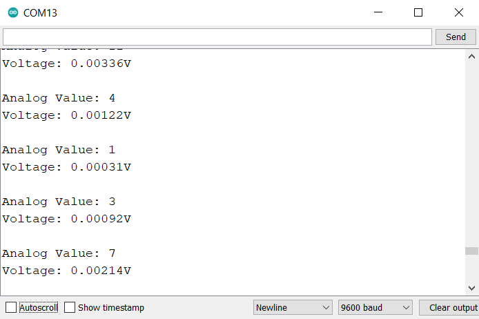
At ADC Value of 1, the voltage measured was 0.00031V which is 0.31mV. Therefore, the minimum voltage that Arduino UNO R4 measures is 0.31mV.
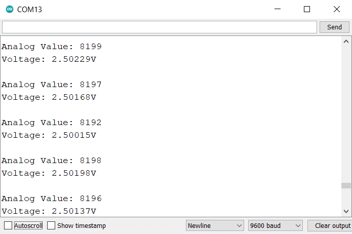
At 2.5V, the measured ADC Value is 8,192.
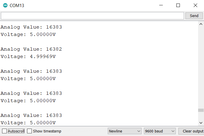
At 5V, the measured ADC Value is 16,383.
Comparision Between 10, 12 & 14 Bit ADC of Arduino R4 Minima
Here’s a comparison table based on the provided data for 10-bit, 12-bit, and 14-bit ADC readings:
| Feature/Specification | 10-bit ADC | 12-bit ADC | 14-bit ADC |
|---|---|---|---|
| Max Discrete Values | 1,024 | 4,096 | 16,384 |
| Range of Values | 0 to 1,023 | 0 to 4,095 | 0 to 16,383 |
| Resolution (Min. Voltage) | 4.89mV | 1.22mV | 0.31mV |
| ADC Value at 2.5V | 512 | 2,048 | 8,192 |
| ADC Value at 5V | 1,023 | 4,095 | 16,383 |
This table now provides a concise comparison of the readings and characteristics of 10-bit, 12-bit, and 14-bit ADCs of the Arduino UNO R4 Minima Board.

")


2 Comments
Thank you for your post. Do you have some DAC examples, because it is not clear to me, which pin I have to use concretely ? Regards
Check our website. The DAC example is there.