

Overview
This article is about the usage of the LD2410 Human Presence Detection Sensor with ESP32. Earlier we used motion detection sensors like PIR Sensor to detect motion when any object is moving. The PIR Sensor works by measuring the infrared (IR) light emitted from, or reflected by, that object.
The Hi-Link LD2410 mmWave radar sensor is a game-changer for precise human presence detection. Unlike traditional PIR sensors that only trigger on movement, the LD2410 detects both stationary occupants (e.g., someone sitting or sleeping) and motion. This makes it ideal for automation scenarios where accuracy is critical.
In this tutorial, we’ll understand the LD2410 capabilities by interfacing it with an ESP32 microcontroller. We will create a versatile Human Presence Detection System. The setup includes two LEDs: a red LED to signal when a person is stationary (at rest) and a green LED to indicate active motion. Additionally, real-time detection data, including distance metrics (up to 6 meters), will be displayed on a 0.96-inch OLED screen, providing immediate visual feedback. A 60GHz mmWave sensor called C1001 is also available in market, which is more advanced.
Bill of Materials
We need following components for this tutorial. You can purchase all these components from the given links.
| S.N. | Components Name | Quantity | Purchase Link |
|---|---|---|---|
| 1 | ESP32 Board | 1 | Amazon | AliExpress |
| 2 | LD2410 Millimeter Wave Presence Sensor | 1 | Amazon | AliExpress |
| 3 | 0.96" OLED Display | 1 | Amazon | AliExpress |
| 4 | Connecting Wires | 10 | Amazon | AliExpress |
| 5 | Breadboard | 1 | Amazon | AliExpress |
Different Types of HiLink Millimeter Wave Presence Sensor
HiLink manufactures 6 different types of HiLink Millimeter Wave Presence Sensors. They are named as LD2410C, LD2410S, LD2450, LD2411, LD2410B, and LD2461.

Here are the differences between these sensors.
| Model | Detection Range | Key Features | Supported Protocols | Use Cases |
|---|---|---|---|---|
| LD2410B | Up to 6 meters | Basic human presence detection (stationary/moving), UART/GPIO control | UART, GPIO | Home automation, lighting control |
| LD2410C | Up to 6 meters | Bluetooth for configuration, reduced false triggers, optimized static detection | UART, GPIO, Bluetooth | Offices, security systems |
| LD2410S | Up to 5 meters | Compact design, low power consumption, simplified configuration | UART | IoT devices, small spaces |
| LD2450 | Up to 8 meters | Multi-zone detection (3 zones), Bluetooth Low Energy (BLE) | UART, BLE | Retail analytics, large-area monitoring |
| LD2411-S | Moving: 6m, Micro-motion: 3.5m | Directional sensing (±20° azimuth, ±45° elevation), motion/micro-motion detection | UART, Bluetooth | Smart homes, access control, lighting |
| LD2461 | Moving: 8m, Static: 6m | 3D spatial sensing, multi-target tracking (up to 5 targets), Ethernet support | UART, Ethernet | Industrial automation, smart cities |
In case you are looking for BLE or WiFi connectivity, you should choose the sensor based on the following table.
| Feature | LD2410B | LD2410C | LD2410S | LD2450 | LD2411-S | LD2461 |
|---|---|---|---|---|---|---|
| Bluetooth | ❌ | ✔️ | ❌ | ✔️ (BLE) | ✔️ | ❌ |
| Angle Detection | ❌ | ❌ | ❌ | ❌ | ✔️ (±20°) | ✔️ (3D spatial) |
| Multi-Target Tracking | ❌ | ❌ | ❌ | ❌ | ❌ | ✔️ (5 targets) |
| Industrial Use | ❌ | ❌ | ❌ | ❌ | ❌ | ✔️ (Ethernet) |
For DIY projects, the LD2410B & LD2410C are popular for their balance of cost and performance. The LD2450 and LD2461 cater to professional setups requiring scalability and precision.
LD2410C mmWave Radar Sensor
The HLK-LD2410C is a 24GHz FMCW (Frequency-Modulated Continuous Wave) radar module designed for human presence detection.
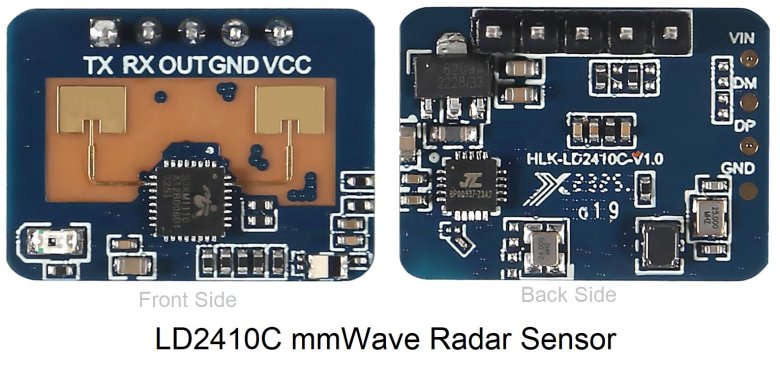
It detects both stationary (e.g., sitting, sleeping) and moving humans up to 6 meters, with a resolution of 0.75m. Ideal for smart home automation, security systems, and energy-saving applications.
LD2410C Sensor Working
The HLK-LD2410C sensor operates using Frequency-Modulated Continuous Wave (FMCW) radar technology. It emits a continuous microwave signal that linearly increases in frequency over time. When this signal encounters an object—such as a human—the reflected wave is captured by the sensor.
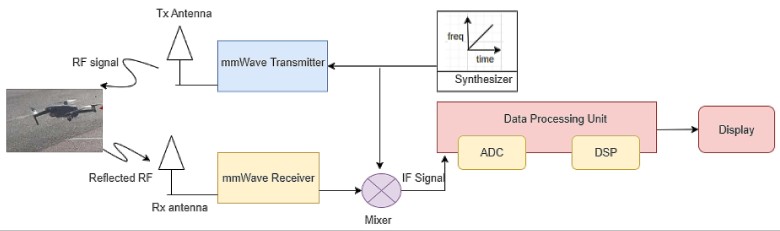
By analyzing the frequency difference and time delay between the transmitted and reflected signals, the sensor calculates the target’s distance and distinguishes between stationary (e.g., sitting, sleeping) and moving humans.
Embedded algorithms further process this data to filter out non-human objects (e.g., pets, moving curtains) by evaluating energy patterns and motion characteristics unique to humans, ensuring reliable detection even in complex environments.
LD2410C Features & Specifications
- Detection Range: 0.75–6 meters (adjustable).
- Angular Coverage: ±60° horizontal.
- Communication: UART (256000 baud), GPIO, Bluetooth (BLE) for configuration.
- Power: 5V DC, ~79mA average current.
- Dimensions: 16mm × 22mm.
- Key Features:
-
- Adjustable sensitivity zones.
- Visual configuration tools (PC/mobile app).
- OTA firmware updates via Bluetooth.
LD2410C Pinout
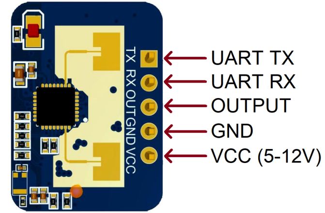
The LD2410C has 5 Pins as follows:
| Pin | Symbol | Function |
|---|---|---|
| 1 | UART_Tx | Serial data transmission (to host) |
| 2 | UART_Rx | Serial data reception (from host) |
| 3 | OUT | High/Low output (human detected) |
| 4 | GND | Ground |
| 5 | VCC | 5-12V power input |
LD2410C Applications & Use
- Smart Lighting: Auto-control lights based on human presence.
- Security Systems: Detect intrusions or unauthorized presence.
- Appliance Control: Wake/sleep TVs, ACs, or displays when humans enter/leave.
- Safety Systems: Prevent UV lamp activation when humans are nearby.
- Installation: Wall/ceiling-mounted; works through non-metallic materials (plastic, glass).
Note: The LD2410C’s Bluetooth support enables wireless tuning via the HLKRadarTools app, distinguishing it from the LD2410B/S models. Refer to LD2410C Datasheet for more detailed information.
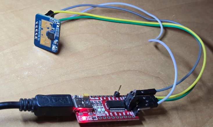
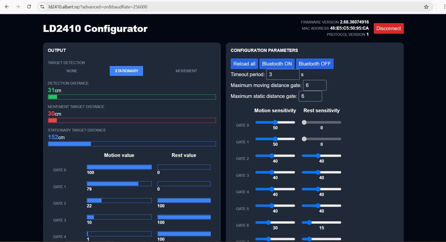
LD2410C Sensor Configuration and Data Visualization
You can use different tools to see the data from the sensor. The two most common ones are the LD2410 Tool (provided by the sensor manufacturer) and the LD2410 Web Configurator.
To use them first connect the sensor with a USB-to-TTL Converter module (FTDI Module).
To start:
- Open one of the tools.
- Set the correct baud rate (usually 256,000) and select the right COM port (as configured earlier).
- Click “Start” to begin receiving data.
The tool will display a graphical view of the sensor’s detections, showing different zones around it. Each zone represents a different sensitivity range. If you run into connection issues, make sure no other programs (like the Arduino IDE) are using the same port.
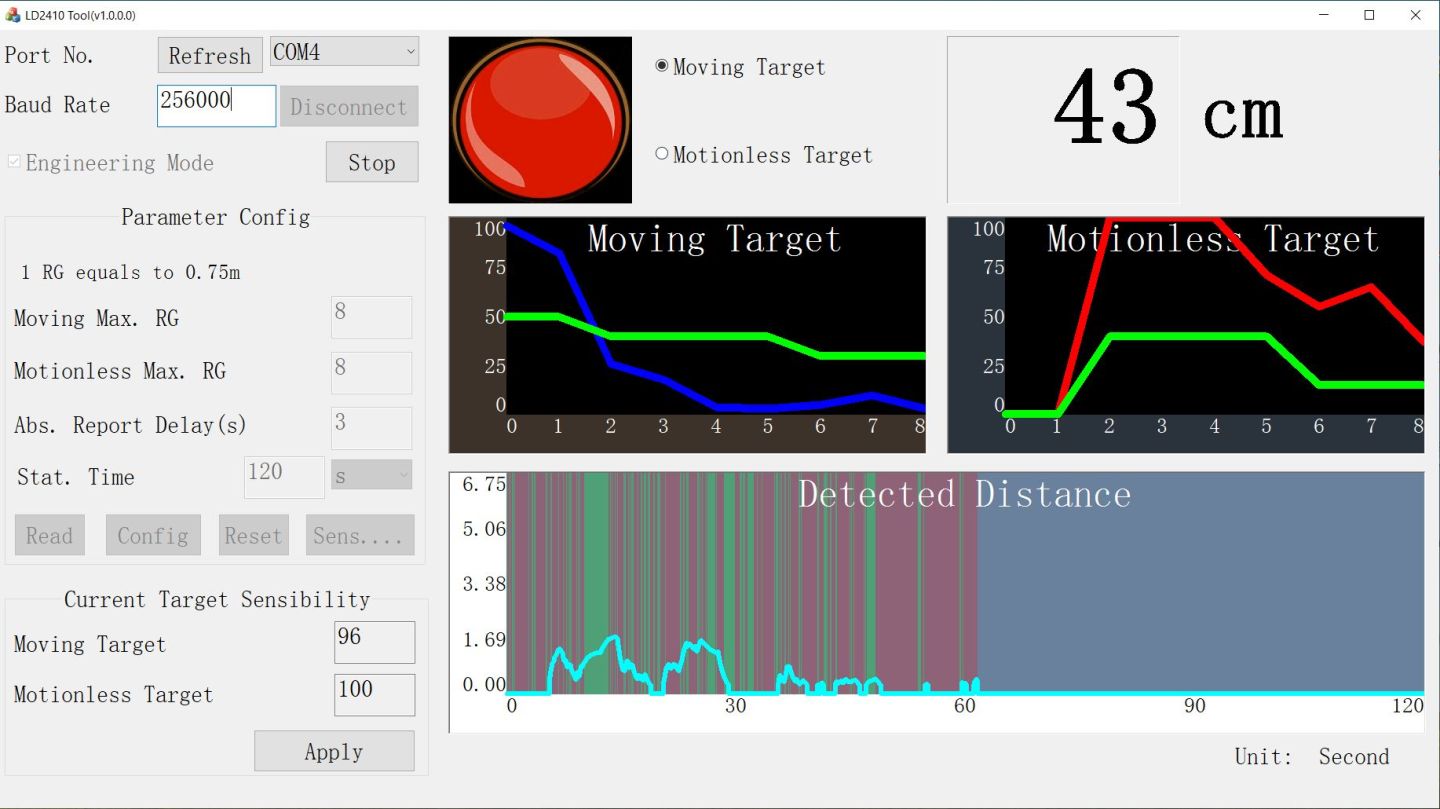
The sensor has eight zones, and you can adjust their sensitivity. As you move closer or farther from the sensor, you’ll see the zones activate in real-time. You can increase or decrease sensitivity for each zone based on your needs. For example, you might want higher sensitivity for detecting movement far away and lower sensitivity for areas close to the sensor.
To fine-tune the settings:
- Double-click on the zone settings in the tool.
- Adjust “moving sensitivity” and “stationary sensitivity” as needed.
This customization helps the sensor work better for your specific project, whether it’s for indoor motion detection or outdoor security monitoring.
Interfacing LD2410 with ESP32 – Human Presence Detection
Now let us interface the LD2410C with ESP32 and write some Arduino C++ Code for Human Presence Detection. Here is the connection diagram which is very simple.

The Pin connection is as follows.
| ESP32 Pin | LD2410C Pin |
|---|---|
| GPIO 16 | TX |
| GPIO 17 | RX |
| GND | GND |
| 5V | VCC |
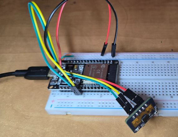
Connect the LD2410C with ESP32 on a breadboard or simply use female-to-female jumper wires.
Basic ESP32 LD2410 Test Code for Human Presence Detection
Lets develop an Arduino C++ Code to interface LD2410C Sensor with ESP32. There is a dedicated library written for Hi-Link LD2410 24Ghz FMCW radar sensor. First Download the LD2410 Library and add it to the Arduino library folder.
The code initializes the radar on designated RX and TX pins (16 and 17) and sets up a communication baud rate of 256000. Once the radar is initialized, the code checks and reports the firmware version to confirm connectivity.
In the loop() function, the code continuously checks if the radar sensor is connected and reads data at intervals of at least 1000 milliseconds. If a target is detected, the code distinguishes between stationary and moving targets, reporting their respective distances and energy levels to the Serial monitor. If no targets are detected within the timeframe, it reports “No target“.
Copy the code and paste it on your Arduino IDE editor window.
|
1 2 3 4 5 6 7 8 9 10 11 12 13 14 15 16 17 18 19 20 21 22 23 24 25 26 27 28 29 30 31 32 33 34 35 36 37 38 39 40 41 42 43 44 45 46 47 48 49 50 51 52 53 54 55 56 57 58 59 60 61 62 63 64 65 66 67 68 69 70 71 |
#define MONITOR_SERIAL Serial #define RADAR_SERIAL Serial1 #define RADAR_RX_PIN 16 #define RADAR_TX_PIN 17 #include <ld2410.h> ld2410 radar; uint32_t lastReading = 0; void setup(void) { MONITOR_SERIAL.begin(115200); // Feedback over Serial Monitor // radar.debug(MONITOR_SERIAL); Uncomment to show debug information from the library on the Serial Monitor. By default this does not show sensor reads as they are very frequent. RADAR_SERIAL.begin(256000, SERIAL_8N1, RADAR_RX_PIN, RADAR_TX_PIN); // UART for monitoring the radar delay(500); MONITOR_SERIAL.print(F("\nConnect LD2410 radar TX to GPIO:")); MONITOR_SERIAL.println(RADAR_RX_PIN); MONITOR_SERIAL.print(F("Connect LD2410 radar RX to GPIO:")); MONITOR_SERIAL.println(RADAR_TX_PIN); MONITOR_SERIAL.print(F("LD2410 radar sensor initialising: ")); if (radar.begin(RADAR_SERIAL)) { MONITOR_SERIAL.println(F("OK")); MONITOR_SERIAL.print(F("LD2410 firmware version: ")); MONITOR_SERIAL.print(radar.firmware_major_version); MONITOR_SERIAL.print('.'); MONITOR_SERIAL.print(radar.firmware_minor_version); MONITOR_SERIAL.print('.'); MONITOR_SERIAL.println(radar.firmware_bugfix_version, HEX); } else { MONITOR_SERIAL.println(F("not connected")); } } void loop() { radar.read(); if (radar.isConnected() && millis() - lastReading > 1000) // Report every 1000ms { lastReading = millis(); if (radar.presenceDetected()) { if (radar.stationaryTargetDetected()) { Serial.print(F("Stationary target: ")); Serial.print(radar.stationaryTargetDistance()); Serial.print(F("cm energy:")); Serial.print(radar.stationaryTargetEnergy()); Serial.print(' '); } if (radar.movingTargetDetected()) { Serial.print(F("Moving target: ")); Serial.print(radar.movingTargetDistance()); Serial.print(F("cm energy:")); Serial.print(radar.movingTargetEnergy()); } Serial.println(); } else { Serial.println(F("No target")); } } } |
For the tools menu, select the ESP32 Board and the COM port. Then hit the upload button to upload the code. Once uploading is done open the Serial Monitor.
In the Serial Monitor, if you see the “LD2410 radar sensor initializing: OK” indicates that the radar has successfully initialized and is ready to operate.
When the object is detected, the Serial monitor will show the stationary or moving target along with the distance of the target from the sensor in centimeters.
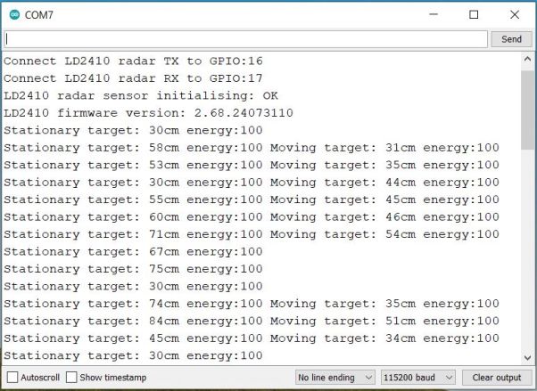
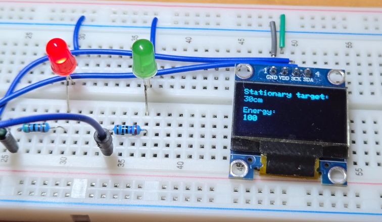
- Stationary Target: This indicates an object detected by the radar that is not moving within its detection range, providing its distance from the sensor.
- Moving Target: This refers to an object that the radar detects as moving within its range, also giving the distance to the object and its motion status.
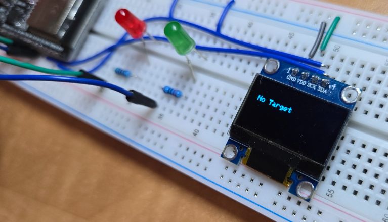
- No Target: This message is displayed when the radar sensor does not detect any object within its range.
- Energy: The “energy” value likely represents the intensity or strength of the radar’s return signal from the detected object, which can help in assessing the object’s size or material characteristics.
LD2410 with ESP32 – LED Indications & OLED Display
Now lets add two LED indications and OLED Display to ESP32 & LD2410 Circuit for practical applications. Here is the circuit diagram for this guide.
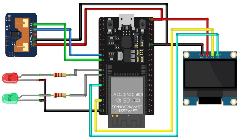
The red LED and green LED is connected to GPIO18 and GPIO19 of ESP32 via 330-ohm resistor. Similarly, the 0.96″ I2C OLED Display is connected via I2C Pin of ESP32.
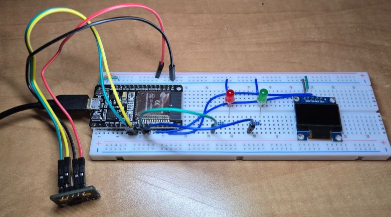
The circuit above is assembled on breadboard as per the circuit diagram.
Modified Code with LED & OLED Indications
The following code has additional LED and OLED control lines of code based on data from LD2410 & ESP32. The code also requires Adafruit SSD1306 library for OLED Display.
In the following code, the logic to control the LEDs based on the radar’s detection status is added.
- Red LED turns on when a stationary target is detected.
- Both LEDs turn on when a moving target is detected.
- Both LEDs turn off when no target is detected.
Similarly, the distance of the stationary or moving object is displayed along with the energy level.
|
1 2 3 4 5 6 7 8 9 10 11 12 13 14 15 16 17 18 19 20 21 22 23 24 25 26 27 28 29 30 31 32 33 34 35 36 37 38 39 40 41 42 43 44 45 46 47 48 49 50 51 52 53 54 55 56 57 58 59 60 61 62 63 64 65 66 67 68 69 70 71 72 73 74 75 76 77 78 79 80 81 82 83 84 85 86 87 88 89 90 91 92 93 94 95 96 97 98 99 100 101 102 103 104 105 106 107 108 109 110 111 112 113 114 115 116 117 118 119 120 121 122 123 124 125 126 127 128 129 130 131 132 133 134 135 136 137 138 139 140 141 142 143 144 145 146 147 148 149 150 151 152 153 154 155 156 |
#include <Adafruit_SSD1306.h> #include <ld2410.h> #define MONITOR_SERIAL Serial #define RADAR_SERIAL Serial1 #define RADAR_RX_PIN 16 #define RADAR_TX_PIN 17 #define RED_LED_PIN 18 // Red LED connected to GPIO 18 #define GREEN_LED_PIN 19 // Green LED connected to GPIO 19 #define SCREEN_WIDTH 128 // OLED display width, in pixels #define SCREEN_HEIGHT 64 // OLED display height, in pixels #define OLED_RESET -1 //Reset pin # (or -1 if sharing Arduino reset pin) #define SCREEN_ADDRESS 0x3C //See datasheet for Address Adafruit_SSD1306 display(SCREEN_WIDTH, SCREEN_HEIGHT, &Wire, OLED_RESET); ld2410 radar; uint32_t lastReading = 0; void setup(void) { MONITOR_SERIAL.begin(115200); // Feedback over Serial Monitor RADAR_SERIAL.begin(256000, SERIAL_8N1, RADAR_RX_PIN, RADAR_TX_PIN); // UART for monitoring the radar pinMode(RED_LED_PIN, OUTPUT); // Set the red LED pin as an output pinMode(GREEN_LED_PIN, OUTPUT); // Set the green LED pin as an output digitalWrite(RED_LED_PIN, LOW); // Ensure red LED is off digitalWrite(GREEN_LED_PIN, LOW); // Ensure green LED is off delay(500); // SSD1306_SWITCHCAPVCC = generate display voltage from 3.3V internally if (!display.begin(SSD1306_SWITCHCAPVCC, SCREEN_ADDRESS)) { Serial.println(F("SSD1306 allocation failed")); for (;;); // Don't proceed, loop forever } delay(500); display.clearDisplay(); MONITOR_SERIAL.print(F("\nConnect LD2410 radar TX to GPIO:")); MONITOR_SERIAL.println(RADAR_RX_PIN); MONITOR_SERIAL.print(F("Connect LD2410 radar RX to GPIO:")); MONITOR_SERIAL.println(RADAR_TX_PIN); MONITOR_SERIAL.print(F("LD2410 radar sensor initialising: ")); if (radar.begin(RADAR_SERIAL)) { MONITOR_SERIAL.println(F("OK")); MONITOR_SERIAL.print(F("LD2410 firmware version: ")); MONITOR_SERIAL.print(radar.firmware_major_version); MONITOR_SERIAL.print('.'); MONITOR_SERIAL.print(radar.firmware_minor_version); MONITOR_SERIAL.print('.'); MONITOR_SERIAL.println(radar.firmware_bugfix_version, HEX); } else { MONITOR_SERIAL.println(F("not connected")); display.clearDisplay(); display.setTextColor(SSD1306_WHITE); display.setCursor(0, 20); display.setTextSize(1); display.print("not connected"); display.display(); } } void loop() { radar.read(); if (radar.isConnected() && millis() - lastReading > 1000) // Report every 1000ms { lastReading = millis(); if (radar.presenceDetected()) { if (radar.stationaryTargetDetected()) { digitalWrite(RED_LED_PIN, HIGH); // Turn on red LED digitalWrite(GREEN_LED_PIN, LOW); // Ensure green LED is off Serial.print(F("Stationary target: ")); Serial.print(radar.stationaryTargetDistance()); Serial.print(F("cm energy:")); Serial.print(radar.stationaryTargetEnergy()); Serial.print(' '); display.clearDisplay(); display.setTextColor(SSD1306_WHITE); display.setTextSize(1); display.setCursor(5, 5); display.print("Stationary target:"); display.setCursor(5, 15); display.print(radar.stationaryTargetDistance()); display.print("cm"); display.setCursor(5, 30); display.print("Energy:"); display.setCursor(5, 40); display.print(radar.stationaryTargetEnergy()); display.display(); } if (radar.movingTargetDetected()) { digitalWrite(RED_LED_PIN, HIGH); // Turn on red LED digitalWrite(GREEN_LED_PIN, HIGH); // Turn on green LED Serial.print(F("Moving target: ")); Serial.print(radar.movingTargetDistance()); Serial.print(F("cm energy:")); Serial.print(radar.movingTargetEnergy()); display.clearDisplay(); display.setTextColor(SSD1306_WHITE); display.setTextSize(1); display.setCursor(5, 5); display.print("Moving target:"); display.setCursor(5, 15); display.print(radar.movingTargetDistance()); display.print("cm"); display.setCursor(5, 30); display.print("Energy:"); display.setCursor(5, 40); display.print(radar.movingTargetEnergy()); display.display(); } } else { digitalWrite(RED_LED_PIN, LOW); // Turn off red LED digitalWrite(GREEN_LED_PIN, LOW); // Turn off green LED Serial.println(F("No target")); display.clearDisplay(); display.setTextColor(SSD1306_WHITE); display.setTextSize(1); display.setCursor(10, 20); display.print("No Target"); display.display(); } Serial.println(); } } |
Upload the above code to the ESP32 Board. Once code uploading is done LD2410 is ready for testing with ESP32.
When No Target is detected, both LED turn OFF and OLED shows “No Target” message.
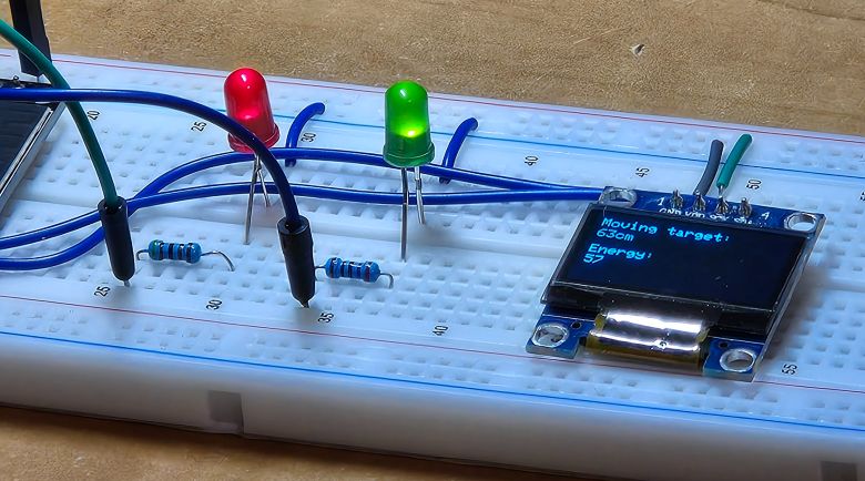
When the Target is detected, and is stationary the Red LED turn ON and OLED shows “Target Distance” along with energy level.
If the Target is detected, and is moving, both the Red & Green LED turn ON and OLED shows “Target Distance” along with energy level.
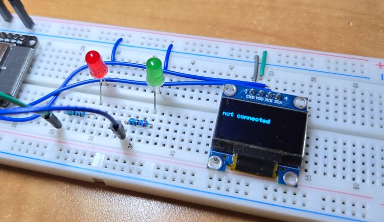
In case, if there is any hardware connection issue, the OLED shows “No Connection” message
This is how you can use LD2410 Millimeter Wave Human Presence Detection Sensor with ESP32 Microcontroller to detect moving or stationary human more precisely.
Ensure that the power requirements of the LD2410C are compatible with what the ESP32 can provide. If the radar requires a higher current than the ESP32 can deliver, an external power source might be necessary. Also, be mindful of the logic levels for communication; if the LD2410C operates at a different voltage than the ESP32’s 3.3V logic, a level shifter might be needed to ensure proper operation and to avoid damaging either component.
Video Tutorial & Guide


