

Introduction
In this guide, we will learn the essential steps for geting started with the Arduino UNO R4 Minima board. From setting up the board to writing your first program, this guide aims to provide a comprehensive overview for beginners and enthusiasts alike.

Whether you’re prototyping a new gadget, learning about microcontrollers, or diving into IoT projects, the R4 Minima is a versatile tool that can help bring your ideas to fruition.
Overview of Arduino UNO R4 Minima Board
Equipped with a powerful 32-bit microcontroller from Renesas, the Arduino Uno R4 MINIMA boasts superior processing capabilities and increased memory. While it maintains the same form factor, pin-out, and 5V operating voltage as its predecessor, the Uno R3, it ensures a smooth transition for ongoing projects. Its compatibility with existing shields and accessories positions the Uno R4 MINIMA as a trusted tool for both novices and experienced electronics aficionados.

Key features of the board include its enhanced memory and accelerated clock speed, facilitating precise computations and the management of intricate projects. The Uno R4 MINIMA also comes with an array of integrated peripherals, such as a 12-bit DAC, CAN BUS, and OP AMP, offering users greater versatility in their creations.
Additionally, the board supports an extended input voltage range, accommodating power supplies of up to 24V. This adaptability simplifies the integration with devices like motors, LED strips, and other actuators by using a unified power source. A notable addition is the board’s inherent Human Interface Device (HID) support, allowing it to mimic a mouse or keyboard when tethered to a computer via USB.
Main Features of Arduino Uno R4 Minima
The Arduino UNO R4 Minima, with the model number R7FA4M1AB3CFM#AA0, is a versatile development board packed with a multitude of features. Here’s a comprehensive overview of its specifications:
1. Microprocessor:
- Core: 48 MHz Arm® Cortex®-M4 microprocessor.
- Special Feature: Equipped with a floating point unit (FPU) for enhanced computational capabilities.
2. Power:
- Operating Voltage: 5 V.
- Input Voltage (VIN): Recommended range is 6-24 V.
- Power Source: Can be powered via a USB-C® at 5 V.
- Protection: Features Schottky diodes for overvoltage and reverse polarity protection.
- Connection: Barrel jack connected directly to the VIN pin.
3. Memory:
- Flash Memory: 256 kB.
- SRAM: 32 kB.
- Data Memory (EEPROM): 8 kB.
4. Pins:
- Digital Pins: 14x GPIO pins labeled D0-D13.
- Analog Input Pins: 6x pins labeled A0-A5.
- PWM Pins: 6x pins specifically D3, D5, D6, D9, D10, and D11.
5. Peripherals:
- Touch Sensing: Capacitive Touch Sensing Unit (CTSU)
- USB Module: USB 2.0 Full-Speed Module (USBFS)
- ADC: Up to 14-bit resolution (ADC Usage Guide)
- DAC: Up to 12-bit resolution (DAC Usage Guide)
- Additional Feature: Operational Amplifier (OPAMP)
6. Communication:
- UART: Available on pins D0 and D1.
- SPI: Accessible via pins D10-D13 and the ICSP header.
- I2C: Available on pins A4, A5, SDA, and SCL.
- CAN: Available on pins D4 and D5, but an external transceiver is required for operation.
7. Special Features:
- Real-time Clock (RTC): Ensures accurate timekeeping.
- Memory Protection Unit (MPU): Provides enhanced security for memory sections.
- Digital Analog Converter (DAC): Allows for precise analog operations.
With its robust set of features, the Arduino UNO R4 Minima is well-suited for a wide range of applications, from simple DIY projects to complex industrial applications. Whether you’re a beginner or an experienced developer, this board offers the tools and flexibility needed to bring your ideas to life.
Arduino UNO R4 Minima Block Diagram
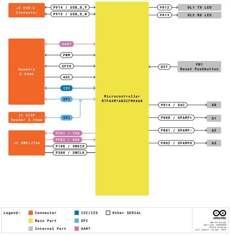
Arduino UNO R4 Minima Pinout
The Arduino UNO R4 Minima offers a variety of pins for both analog and digital functions.

Power Pins
| Pin | Function | Description |
|---|---|---|
| VIN | Input | Voltage input (6V to 24V) |
| +3V3 | Output | 3.3V power rail |
| +5V | Output | 5V power rail |
| GND | – | Ground |
| IOREF | Output | Reference voltage (5V) |
Digital GPIO Pins
| Pin | Function | Description |
|---|---|---|
| D0-D13 | GPIO | General-purpose pins |
| D3, D5, D6, D9, D10, D11 | PWM | Pulse Width Modulation |
| D1/TX0, D0/RX0 | UART | Serial communication |
| D13/SCK, D12/CIPO, D11/COPI, D10/CS | SPI | Serial Peripheral Interface |
| D5/CANRX0, D4/CANTX0 | CAN | CAN Bus communication |
Analog Pins
| Pin | Function | Description |
|---|---|---|
| A0-A5 | Input | Analog input pins |
| A0 | DAC | Digital to Analog Converter |
| A1, A2 | OPAMP | Operational Amplifier |
| A4, A5 | I²C | I²C communication (SDA and SCL) |
Other Pins
| Pin | Function | Description |
|---|---|---|
| BOOT | Mode | Mode selection |
| Reset | – | Board reset |
| AREF | Input | Analog reference voltage |
Operating Conditions & Power Supply
Recommended Operating Conditions
| Symbol | Description | Min | Typ | Max | Unit |
|---|---|---|---|---|---|
| VIN | Input voltage from VIN pad / DC Jack | 6 | 7.0 | 24 | V |
| VUSB | Input voltage from USB connector | 4.8 | 5.0 | 5.5 | V |
| TOP | Operating Temperature | -40 | 25 | 85 | °C |
Power Options
The Arduino board offers multiple power supply options:
- VIN Pin: Power can be provided through the VIN pin.
- Barrel Jack: An alternative is to use the barrel jack.
- USB-C® Connector: The board can also be powered via the USB-C® connector.
When power is channeled through the VIN, the ISL854102FRZ buck converter efficiently steps down the voltage to 5 V. Both the VUSB and the barrel jack connector, along with the VIN pins, are directly linked to this ISL854102FRZ buck converter.
When powering the board via USB, it’s worth noting that the RA4M1 microcontroller receives approximately ~4.7 V, a slight reduction due to the Schottky diode drop.
Pin Voltage
The UNO R4 Minima operates at 5V, and this applies to all the pins on the board with the exception of the 3.3V pin. This specific pin sources its power from the VCC_USB pin on the R7FA4M1AB3CFM#AA0. Notably, it is not linked to the buck converter.
Pin Current Limitations
The GPIOs of the R7FA4M1AB3CFM#AA0 microcontroller are designed to handle a maximum current of 8 mA. It’s crucial to avoid connecting devices that demand a higher current directly to these GPIOs.
For powering external devices that necessitate greater power, such as servo motors, always opt for an external power supply.
Getting Started with Arduino UNO R4 Minima Board
If you want to program your UNO R4 Minima while offline you need to install the Arduino® Desktop IDE. To connect the UNO R4 Minima to your computer, you will need a Type-C® USB cable, which can also provide power to the board.
Download and Install Arduino IDE 2.xx
The Arduino IDE, known as Arduino Integrated Development Environment, provides all the software support needed to complete an Arduino project. It is a programming software specifically designed for Arduino, provided by the Arduino team, that allows us to write programs and upload them to the Arduino board.
- Vist Arduino IDE 2.0.0 Page.
- Download the IDE for your OS version.
- Install the Arduino IDE
- When the installation is complete, you can start the Arduino IDE
- When you first open Arduino IDE 2.x, it automatically installs the Arduino AVR Boards, built-in libraries, and other required files.

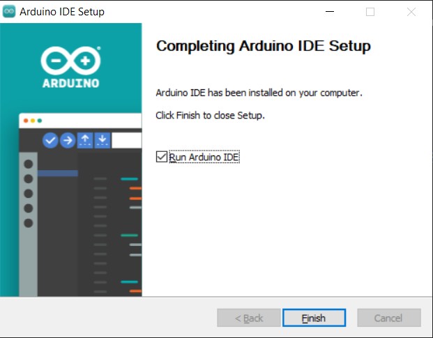
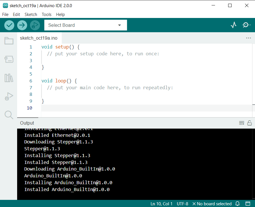
Now the Arduino IDE Download has been complete.
Connecting Arduino UNO R4 Minima Board to Computer
Insert Type-C USB Cable to your Arduino UNO R4 Minima Board. Connect the other end of the Board to the USB port of Computer.

Select the Arduino UNO R4 Board from Board Selection list as well as COM port.

Since the Arduino UNO R4 Board is not installed on the Arduino IDE, so following message will pop up asking for Board installation.

You can click on “Yes” to begin the board installation.
After the installation is complete, the Arduino IDE would show the above message.
Example 1: Blinking of LED
The first project on Getting Started Arduino UNO R4 Minima is Blinking of LED. Blinking an LED is often considered the “Hello World” of the Arduino world. It’s a simple project that helps beginners get acquainted with basic Arduino programming and circuitry.
Copy the following code and paste it on your Arduino IDE.
|
1 2 3 4 5 6 7 8 9 10 11 12 13 14 15 16 |
// Define the LED pin int ledPin = 13; // Setup function void setup() { // Set the LED pin as OUTPUT pinMode(ledPin, OUTPUT); } // Main loop function void loop() { digitalWrite(ledPin, HIGH); // Turn the LED on delay(1000); // Wait for 1 second (1000 milliseconds) digitalWrite(ledPin, LOW); // Turn the LED off delay(1000); // Wait for 1 second (1000 milliseconds) } |
Click on upload button to upload the code to the Arduino UNO R4 Minima Board. Once uploading is done, the on-board LED at Pin 13 will turn ON/OFF every one seconds.

You can change the delay to observe the change in blinking interval.
Example 2: Flowing LED Lights
Flowing LED lights, often referred to as “chasing lights” or “running lights,” is a visual effect where individual LEDs light up in sequence, creating the illusion of movement. This effect can be seen in various applications, from decorative lighting to indicators on electronic devices.
We can develop a flowing LED patterns using Arduino UNO R4 Minima Board and some LED with resistors. Here is the schematic for this guide.

You can use a breadboard to connect all the LEDs with Arduino. We used Digital Pin 2, 3, 4, 5, 6, 7 with 330-ohm resistor to connect the positive Pin of 6 LEDs. The other end of the LED is connected to the GND.

You can use a breadboard for assembly and use jumper wires for establishing connections.
Here is the code for the Colorful Flowing LED lights. Copy the code and paste it on your Arduino IDE.
|
1 2 3 4 5 6 7 8 9 10 11 12 13 14 15 16 17 18 19 20 21 22 23 24 |
const int numLEDs = 6; // Number of LEDs const int ledPins[numLEDs] = {2, 3, 4, 5, 6, 7}; // Pins where LEDs are connected void setup() { for (int i = 0; i < numLEDs; i++) { pinMode(ledPins[i], OUTPUT); // Set each LED pin as an output } } void loop() { // Flow from the first LED to the last for (int i = 0; i < numLEDs; i++) { digitalWrite(ledPins[i], HIGH); // Turn on the LED delay(100); // Wait for 100 ms digitalWrite(ledPins[i], LOW); // Turn off the LED } // Flow back from the last LED to the first for (int i = numLEDs - 1; i >= 0; i--) { digitalWrite(ledPins[i], HIGH); // Turn on the LED delay(100); // Wait for 100 ms digitalWrite(ledPins[i], LOW); // Turn off the LED } } |
Upload the code to the Arduino Board. You will see LED flowing in forward and reverse direction.

Flowing LED lights offer a simple yet effective way to create dynamic lighting effects.
Recommended Arduino UNO R4 Minima Starter Kit
The best Arduino UNO R4 Minima Starter Kit is the SunFounder Ultimate Starter Kit with Original Arduino Uno R4 Minima Board.

The Ultimate Sensor Kit with Arduino Uno R4 Minima is a comprehensive package designed for open-source enthusiasts. The kit includes over 30 cutting-edge modules such as the Ultrasonic Sensor, Flame Sensor, and Pulse Oximeter. Each module comes with beginner-friendly code examples to kickstart your journey.
Dive into the IoT realm with projects that connect the Arduino to platforms like Blynk using the ESP8266 WiFi module. Create innovative systems like the Flame Alert System, Bluetooth-controlled environmental monitor, smart trash can, and more. This kit isn’t just about following instructions; it’s about understanding, experimenting, and inventing unique projects.
Conclusion
The Arduino UNO R4 Minima Board serves as a powerful and versatile platform for both beginners and experienced developers. Its diverse pinout, encompassing power, digital, and analog functionalities, ensures a wide range of applications. From simple tasks like the “Blinking of LED” to more intricate operations like “Flowing LED Lights“, the board’s capabilities are evident. As you embark on your journey with the Getting Started with Arduino UNO R4 Minima, whether it’s for learning or advanced projects, this board promises a seamless and enriching experience.

")


1 Comment
how can you use interrupts on the minima board ?