

Overview:
This post is about interfacing of MCP4725 12-Bit DAC (Digital-to-Analog Converter) Module with Arduino. Using the MCP4725 12-Bit Digital-to-Analog Converter Module, we can generate various analog voltages. This can be helpful in generating various waveforms. Earlier, we learned about Analog-to-Digital Converters like ADS1115 (16-Bit) as well as ADS1220 (24-Bit), but the tutorial is about Digital-to-Analog Converters, which is the reverese of ADC.
Microcontrollers, like the Arduino, are skilled at handling digital tasks, but sometimes we need them to work with the analog world. That’s where DACs (Digital to Analog Converters) come into play. The MCP4725 is a popular DAC choice for Arduino enthusiasts. It’s a 12-bit module, meaning it can translate digital signals into a range of 4096 distinct analog voltages, anywhere from 0V to 5V.
Arduino’s built-in PWM (Pulse Width Modulation) can mimic analog behavior, but it’s not true analog output. For tasks needing genuine analog voltages, like controlling motor speeds or adjusting LED brightness accurately, MCP4725 is a game-changer.
In this, we will use MCP4725 with Arduino to generate various Analog Voltages. Then, we will develop an Arduino code to generate various waveforms like Sine, Square and Triangle. The waveforms will be observed in Oscilloscope and hence accuracy along with performance can be checked.
Bill of Materials
| S.N. | Components | Quantity | Purchase Link |
|---|---|---|---|
| 1 | Arduino Nano Board | 1 | Amazon | AliExpress | SunFounder |
| 2 | MCP4725 DAC Module | 1 | Amazon | AliExpress |
| 3 | Jumper Wires | 10 | Amazon | AliExpress | SunFounder |
| 4 | Breadboard | 1 | Amazon | AliExpress | SunFounder |
MCP4725 12-Bit DAC Chip
The MCP4725 is a prominent member of the DAC family, designed and manufactured by Microchip Technology.

This single-channel, 12-bit, voltage output Digital-to-Analog Converter (DAC) is known for its precision and versatility. It comes with an integrated EEPROM, which allows developers to store configuration settings, and an I2C Compatible Serial Interface, making it a preferred choice for many digital-to-analog conversion applications.
Features of MCP4725
- 12-bit resolution
- I2C protocol interface
- Onboard EEPROM memory
- 0.2 LSB Differential Nonlinearity (DNL)
- External address pin
- Power down mode
- Fast settling time
- Low power consumption
- Rail-to-rail output
- Single supply operation
- External voltage reference
- Eight available addresses
- Standard, fast, and high-speed modes
- Small SOT-23 package
- Extended temperature range
MCP4725 Pin Configuration
The MCP4725, typically available in a 6-pin SOT-23 package, has the following pin configuration:
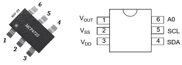
- VOUT: This is the Analog Output pin, where the converted analog signal is obtained.
- VSS: The ground pin.
- VDD: This is the power supply pin. It typically operates between 2.7V to 5.5V.
- SDA: The Serial Data pin for I2C communication.
- SCL: This is the Serial Clock pin for I2C communication.
- A0: Address pin. This pin is used to set the I2C address for the MCP4725. It can be tied to VDD or GND to change the address, especially useful when multiple MCP4725 devices are used on the same I2C bus.
MCP4725 Functional Block Diagram
The MCP4725’s architecture is designed for efficiency. At its core, it houses an input register, a DAC register, and a 12-bit DAC. The input register can update the DAC register directly or via a software reset.
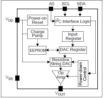
The EEPROM memory is crucial as it stores the DAC input code, which is loaded to the DAC register upon power-up.
MCP4725 I2C Address
The MCP4725 can indeed have the addresses 0x60 or 0x61 based on the state of the A0 pin. The exact address depends on the manufacturer’s configuration and the connection of the A0 pin.
- A0 Pin Connected to GND:
- I2C Address:
0x60(Hexadecimal) - Binary Representation:
1100000
- I2C Address:
- A0 Pin Connected to VDD:
- I2C Address:
0x61(Hexadecimal) - Binary Representation:
1100001
- I2C Address:
Typical Connections of the MCP4725
Interfacing the MCP4725 with microcontrollers is straightforward due to its I2C protocol support. The VDD and GND pins provide power, while the SCL and SDA pins facilitate I2C communication. The VOUT pin is where the analog output can be tapped.
MCP4725 Module or Breakout Board
Since the MCP4725 chip comes in a very small package, it is hard to solder it on a PCB. For hobbyists and developers, the MCP4725 is often available on a breakout board.
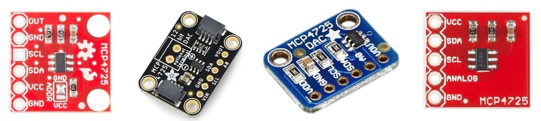
These boards simplify interfacing the chip with various platforms, from Arduino to Raspberry Pi, by breaking out the essential pins and sometimes adding extra features like voltage regulators or additional components for signal conditioning.
MCP4725 Module Schematic
A standard MCP4725 module schematic from Adafruit will showcase the MCP4725 chip at its heart.

Let’s examine the various components of the schematic in detail. Initially, we see two 10K resistors linked to pins 4 and 5, which correspond to the SDA and SCL pins. These resistors serve as pull-up resistors, elevating the pins to the VDD level. They are essential for the correct functioning of the I2C interface. Next, there’s another 10K resistor attached to the A0 pin, determining the I2C address the module will utilize.
Additionally, a 1uF capacitor bridges the VDD and GND pins, acting as a power supply decoupling capacitor to minimize power supply-induced noise. Finally, the JP1 terminal provides access to all the MCP4725 pins for external interfacing.
MCP4725 Module Pinout
On a typical MCP4725 module, you’ll find pins labeled VDD, GND, SCL, SDA, and VOUT. Some modules might also include the A0 pin, providing additional functionality.
You may refer to MCP4725 Datasheet for more information.
Interfacing MCP4725 12-Bit DAC Module with Arduino
Let us see how we can interface the MCP4725 12-Bit DAC Digital-to-Analog Converter Module with Arduino. Here is a connection diagram.

| MCP4725 Pin | Arduino Uno Pin | Description |
|---|---|---|
| VDD | 3.3V or 5V | Power supply for the MCP4725 |
| GND | GND | Ground connection |
| SDA | A4 | I2C data line |
| SCL | A5 | I2C clock line |
| A0 | GND or 3.3V/5V | I2C address selection (optional) |
| VOUT | – | Analog output (can be connected to any circuit or an analog pin for testing) |
Note: The A0 pin determines the I2C address. If connected to GND, the address is 0x60. If connected to VDD (3.3V or 5V), the address is 0x61.

Instead of Arduino UNO, you may use any Arduino Boards like Arduino Nano or Mega and assemble on a breadboard.
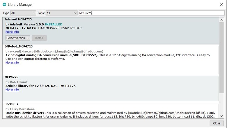
MCP4725 Arduino Library
The Adafruit MCP4725 library is a dedicated library developed by Adafruit Industries to simplify interfacing the MCP4725 DAC with Arduino platforms. This library provides easy-to-use methods to set the DAC output, making it straightforward to generate analog voltages from digital values.
You may follow any method below to install the library
- Arduino IDE Library Manager:
- Open Arduino IDE.
- Navigate to
Sketch>Include Library>Manage Libraries. - In the search box, type “Adafruit MCP4725”.

- Find the Adafruit MCP4725 library in the list and install it.
- Manual Installation:
- Download the library ZIP file from the Adafruit GitHub repository or the Adafruit website.
- In Arduino IDE, go to
Sketch>Include Library>Add .ZIP Library. - Navigate to the downloaded ZIP file and select it
Generating Variable Analog Voltage using MCP4725 & Arduino
Generating a variable analog voltage using the MCP4725 and Arduino is a common application for this DAC module. By varying the digital input to the MCP4725, you can produce a range of analog output voltages.
In the following code, we will generate the 5 different analog voltages from Vout pin of MCP4725.
|
1 2 3 4 5 6 7 8 9 10 11 12 13 14 15 16 17 18 19 20 21 22 23 24 25 26 27 28 29 30 31 32 33 34 35 36 37 38 |
#include <Wire.h> #include <Adafruit_MCP4725.h> Adafruit_MCP4725 dac; #define DAC_RESOLUTION (9) // Set this value to 9, 8, 7, 6 or 5 to adjust the resolution void setup() { Serial.begin(9600); delay(100); // Small delay to ensure Serial is ready. Serial.println("MCP4725 Test"); if (dac.begin(0x61)) //could be 0x60 or 0x62 { Serial.println("MCP4725 Initialized Successfully."); } else { Serial.println("Failed to Initialize MCP4725."); } } void loop() { dac.setVoltage((1 * 4095) / 5, false); //Set voltage to 1V delay(2000); dac.setVoltage((2 * 4095) / 5, false); //Set voltage to 2V delay(2000); dac.setVoltage((3 * 4095) / 5, false); //Set voltage to 3V delay(2000); dac.setVoltage((4 * 4095) / 5, false); //Set voltage to 4V delay(2000); dac.setVoltage(4095, false); //Set voltage to 5V or (Vcc) delay(2000); } |
Upload the above code to the Arduino Nano Board and the setup is ready for testing. For testing the multimeter is required.
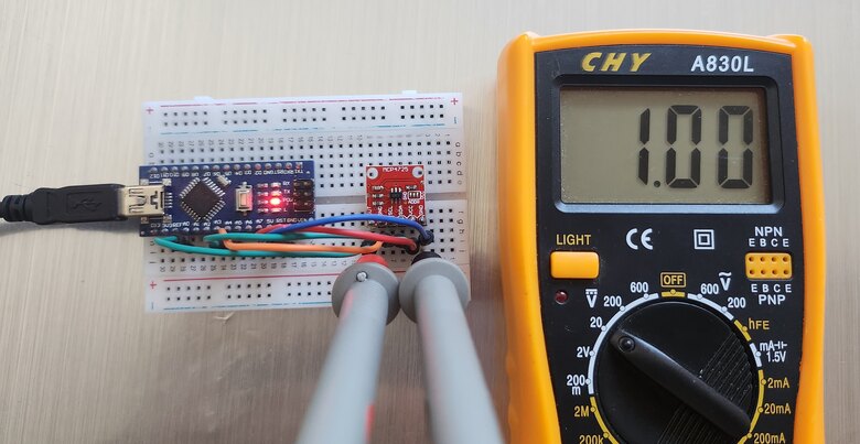
The multimeter will show the reading as 1V, 2V, 3V, 4V and Maximum Voltage after every two seconds.
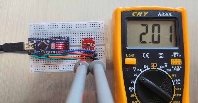
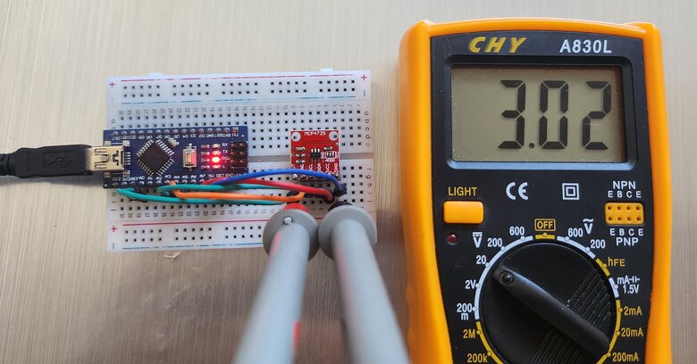
The multimeter reading changes to show the voltage reading as per loop section in the code.
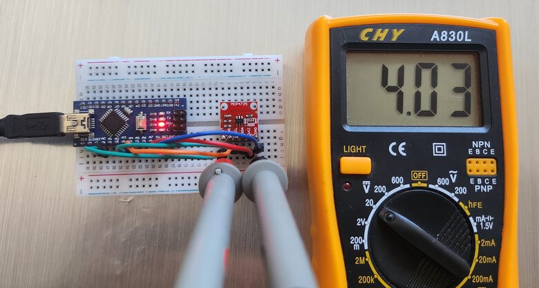
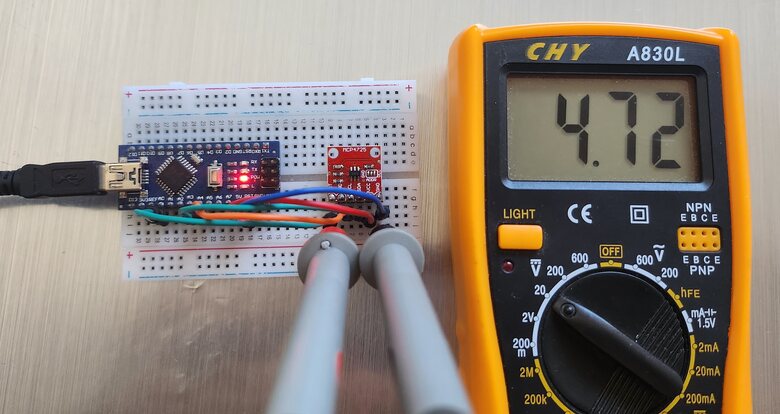
The Arduino UNO/Nano Board 5V Pin sometimes doesn’t provide fixed 5V output. Hence you need to replace 4095 in the code with some tested value.
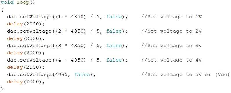
I replaced 4095 with 4350 and it gave proper readings for 1V, 2V, 3V and 4V. This is how you can use MCP4725 Digital-to-Analog Converter with Arduino.
Sine Wave Generator using MCP4725
The MCP4725 12-Bit DAC Module can be interfaced with the Arduino to generate a sine wave as well.
Here is a code for MCP4725 Sine Wave Generator with Arduino.
|
1 2 3 4 5 6 7 8 9 10 11 12 13 14 15 16 17 18 19 20 21 22 23 24 25 26 27 28 29 30 31 32 33 34 35 36 37 38 39 40 41 42 43 44 45 46 47 48 49 50 51 52 53 54 55 56 57 58 59 60 61 62 63 64 65 66 67 68 69 70 71 72 73 74 75 76 77 78 79 80 81 82 83 84 85 86 87 88 89 90 91 92 93 94 95 96 97 98 99 100 101 102 103 104 105 106 |
#include <Wire.h> #include <Adafruit_MCP4725.h> Adafruit_MCP4725 dac; #define DAC_RESOLUTION (9) const PROGMEM uint16_t DACLookup_FullSine_9Bit[512] = { 2048, 2073, 2098, 2123, 2148, 2174, 2199, 2224, 2249, 2274, 2299, 2324, 2349, 2373, 2398, 2423, 2448, 2472, 2497, 2521, 2546, 2570, 2594, 2618, 2643, 2667, 2690, 2714, 2738, 2762, 2785, 2808, 2832, 2855, 2878, 2901, 2924, 2946, 2969, 2991, 3013, 3036, 3057, 3079, 3101, 3122, 3144, 3165, 3186, 3207, 3227, 3248, 3268, 3288, 3308, 3328, 3347, 3367, 3386, 3405, 3423, 3442, 3460, 3478, 3496, 3514, 3531, 3548, 3565, 3582, 3599, 3615, 3631, 3647, 3663, 3678, 3693, 3708, 3722, 3737, 3751, 3765, 3778, 3792, 3805, 3817, 3830, 3842, 3854, 3866, 3877, 3888, 3899, 3910, 3920, 3930, 3940, 3950, 3959, 3968, 3976, 3985, 3993, 4000, 4008, 4015, 4022, 4028, 4035, 4041, 4046, 4052, 4057, 4061, 4066, 4070, 4074, 4077, 4081, 4084, 4086, 4088, 4090, 4092, 4094, 4095, 4095, 4095, 4095, 4095, 4095, 4095, 4094, 4092, 4090, 4088, 4086, 4084, 4081, 4077, 4074, 4070, 4066, 4061, 4057, 4052, 4046, 4041, 4035, 4028, 4022, 4015, 4008, 4000, 3993, 3985, 3976, 3968, 3959, 3950, 3940, 3930, 3920, 3910, 3899, 3888, 3877, 3866, 3854, 3842, 3830, 3817, 3805, 3792, 3778, 3765, 3751, 3737, 3722, 3708, 3693, 3678, 3663, 3647, 3631, 3615, 3599, 3582, 3565, 3548, 3531, 3514, 3496, 3478, 3460, 3442, 3423, 3405, 3386, 3367, 3347, 3328, 3308, 3288, 3268, 3248, 3227, 3207, 3186, 3165, 3144, 3122, 3101, 3079, 3057, 3036, 3013, 2991, 2969, 2946, 2924, 2901, 2878, 2855, 2832, 2808, 2785, 2762, 2738, 2714, 2690, 2667, 2643, 2618, 2594, 2570, 2546, 2521, 2497, 2472, 2448, 2423, 2398, 2373, 2349, 2324, 2299, 2274, 2249, 2224, 2199, 2174, 2148, 2123, 2098, 2073, 2048, 2023, 1998, 1973, 1948, 1922, 1897, 1872, 1847, 1822, 1797, 1772, 1747, 1723, 1698, 1673, 1648, 1624, 1599, 1575, 1550, 1526, 1502, 1478, 1453, 1429, 1406, 1382, 1358, 1334, 1311, 1288, 1264, 1241, 1218, 1195, 1172, 1150, 1127, 1105, 1083, 1060, 1039, 1017, 995, 974, 952, 931, 910, 889, 869, 848, 828, 808, 788, 768, 749, 729, 710, 691, 673, 654, 636, 618, 600, 582, 565, 548, 531, 514, 497, 481, 465, 449, 433, 418, 403, 388, 374, 359, 345, 331, 318, 304, 291, 279, 266, 254, 242, 230, 219, 208, 197, 186, 176, 166, 156, 146, 137, 128, 120, 111, 103, 96, 88, 81, 74, 68, 61, 55, 50, 44, 39, 35, 30, 26, 22, 19, 15, 12, 10, 8, 6, 4, 2, 1, 1, 0, 0, 0, 1, 1, 2, 4, 6, 8, 10, 12, 15, 19, 22, 26, 30, 35, 39, 44, 50, 55, 61, 68, 74, 81, 88, 96, 103, 111, 120, 128, 137, 146, 156, 166, 176, 186, 197, 208, 219, 230, 242, 254, 266, 279, 291, 304, 318, 331, 345, 359, 374, 388, 403, 418, 433, 449, 465, 481, 497, 514, 531, 548, 565, 582, 600, 618, 636, 654, 673, 691, 710, 729, 749, 768, 788, 808, 828, 848, 869, 889, 910, 931, 952, 974, 995, 1017, 1039, 1060, 1083, 1105, 1127, 1150, 1172, 1195, 1218, 1241, 1264, 1288, 1311, 1334, 1358, 1382, 1406, 1429, 1453, 1478, 1502, 1526, 1550, 1575, 1599, 1624, 1648, 1673, 1698, 1723, 1747, 1772, 1797, 1822, 1847, 1872, 1897, 1922, 1948, 1973, 1998, 2023 }; void setup(void) { dac.begin(0x61); Wire.setClock(400000L); // Increase I2C speed to 400kHz } float interpolate(uint16_t index1, uint16_t index2, float fractionBetween) { return (1.0 - fractionBetween) * pgm_read_word(&(DACLookup_FullSine_9Bit[index1])) + fractionBetween * pgm_read_word(&(DACLookup_FullSine_9Bit[index2])); } void loop(void) { uint16_t i; float step = 0.5; // You can adjust this step to change the interpolation resolution for (i = 0; i < 511; i++) // Only loop to 511 to avoid out of bounds on the last value { dac.setVoltage(pgm_read_word(&(DACLookup_FullSine_9Bit[i])), false); delayMicroseconds(500); // This delay might need to be adjusted based on the desired waveform frequency and the time taken for I2C operations // Interpolated value float interpolatedValue = interpolate(i, i + 1, step); dac.setVoltage((uint16_t) interpolatedValue, false); delayMicroseconds(500); // Same delay as above } // For the last value dac.setVoltage(pgm_read_word(&(DACLookup_FullSine_9Bit[511])), false); } |
Upload the above code to the Arduino Board and the sine wave generator is ready.
To observe the Sine Wave connect the Output & GND Pin to the Oscilloscope.
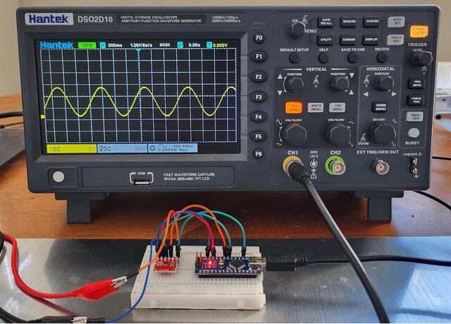
Generating a sine wave using the MCP4725 and Arduino is a great way to produce a smooth analog waveform.
Triangle Wave Generator using MCP4725
Generating a triangle wave using the MCP4725 and Arduino involves incrementing and decrementing the DAC output in a loop to create a linear rise and fall in voltage.
Here’s a complete code to generate a triangle wave.
|
1 2 3 4 5 6 7 8 9 10 11 12 13 14 15 16 17 18 19 20 21 22 23 24 25 26 27 28 29 30 31 32 33 34 35 36 37 38 |
#include <Wire.h> #include <Adafruit_MCP4725.h> Adafruit_MCP4725 dac; const PROGMEM uint16_t DACLookup_Triangle_100[100] = { 0, 82, 164, 246, 328, 410, 491, 573, 655, 737, 819, 901, 983, 1065, 1147, 1229, 1310, 1392, 1474, 1556, 1638, 1720, 1802, 1884, 1966, 2048, 2129, 2211, 2293, 2375, 2457, 2539, 2621, 2703, 2785, 2867, 2948, 3030, 3112, 3194, 3276, 3358, 3440, 3522, 3604, 3686, 3767, 3849, 3931, 4013, 4095, 4013, 3931, 3849, 3767, 3686, 3604, 3522, 3440, 3358, 3276, 3194, 3112, 3030, 2948, 2867, 2785, 2703, 2621, 2539, 2457, 2375, 2293, 2211, 2129, 2048, 1966, 1884, 1802, 1720, 1638, 1556, 1474, 1392, 1310, 1229, 1147, 1065, 983, 901, 819, 737, 655, 573, 491, 410, 328, 246, 164, 82 }; void setup(void) { dac.begin(0x61); // Initialize MCP4725 with address 0x60 } void TRIANGLE(void) { uint16_t i; int freq = analogRead(A0) + 1; // Read frequency from analog pin A0 for (i = 0; i < 100; i++) { dac.setVoltage(pgm_read_word(&(DACLookup_Triangle_100[i])), false); delayMicroseconds(freq); } } void loop(void) { TRIANGLE(); } |
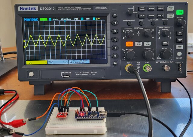
To observe the Triangular Wave connect the Output & GND Pin to the Oscilloscope.
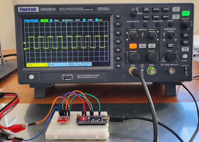
Square Wave Generator using MCP4725
Now lets use the MCP4725 Digital-to-Analog Converter Module with Arduino to generate a square wave form. Generating a square wave using the MCP4725 and Arduino is a straightforward task. The MCP4725 will alternate between two voltage levels to create the square wave.
Here’s the complete code:
|
1 2 3 4 5 6 7 8 9 10 11 12 13 14 15 16 17 18 19 |
#include <Wire.h> #include <Adafruit_MCP4725.h> Adafruit_MCP4725 dac; void setup() { dac.begin(0x61); // Initialize MCP4725 with address 0x60 } void loop() { int freq = analogRead(A0) + 1; // Read frequency from analog pin A0 int halfPeriod = 1000000 / (2 * freq); // Calculate half period in microseconds dac.setVoltage(4095, false); // Set voltage to max (Vcc) delayMicroseconds(halfPeriod); dac.setVoltage(0, false); // Set voltage to ground (0V) delayMicroseconds(halfPeriod); } |
After uploading the code, the Oscilloscope shows the following waveform.
Video Tutorial & Guide

Conclusion
Throughout our exploration, we’ve seen the versatility of the MCP4725 12-Bit DAC Module when interfaced with Arduino, particularly its ability to generate a variety of analog voltages. The practical application of this module was highlighted by producing diverse waveforms like Sine, Square, and Triangle. By observing these waveforms on an oscilloscope, we not only verified their accuracy but also gauged the overall performance of the MCP4725 in tandem with Arduino. This hands-on approach underscores the module’s significance in bridging the digital and analog worlds, making it an invaluable tool for enthusiasts and professionals alike.

")


