

Overview:
In this guide, we’ll explore how to integrate the ADS1220 24-bit ADC Module with Arduino. The ADS1220 breakout board is a 24-bit analog-to-digital converter (ADC) suitable for use with Arduino, ESP8266/32, STM32, and other microcontrollers. The ADS1220 stands out for its impeccable 24-bit resolution, surpassing the capabilities of the 16-bit A/D converter ADS1115.
While Arduino boards are equipped with a built-in 10-bit ADC, its precision is somewhat limited. In contrast, the ADS1220 boasts a 24-bit ADC resolution. To put this into perspective, the smallest voltage that Arduino can detect is 5V / 1024 = 0.0049V (or 4.9mV). On the other hand, the ADS1220 can measure as little as 5V / 16777216 = 0.0000003V (or 0.3uV). This means that the ADS1220 can detect much finer voltage differences than the standard Arduino ADC, making it a superior choice for more precise measurements.
Bill of Materials
The following are the components required for this tutorial. You may purchase all the components from given links.
| S.N. | Components | Quantity | Purchase Link |
|---|---|---|---|
| 1 | Arduino Nano | 1 | Amazon | AliExpress | SunFounder |
| 2 | ADS1220 24-Bit ADC Module | 1 | Amazon | AliExpress |
| 3 | 0.96" I2C OLED Display | 1 | Amazon | AliExpress | SunFounder |
| 4 | 10K Potentiometer | 1 | Amazon | AliExpress |
| 5 | Breadboard | 1 | Amazon | AliExpress |
| 6 | Connecting Wires | 10 | Amazon | AliExpress |
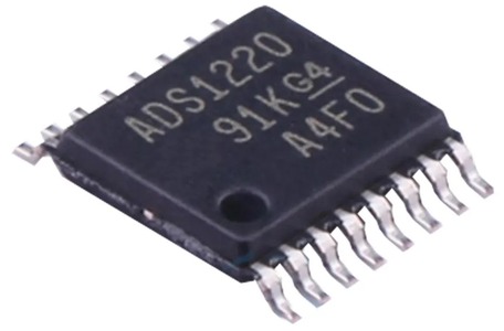
ADS1220 Chip
The ADS1220 chip is the core component of the ADS1220 ADC module. Made by Texas Instruments (TI), this chip is a high-precision 12-bit analog-to-digital converter (ADC).
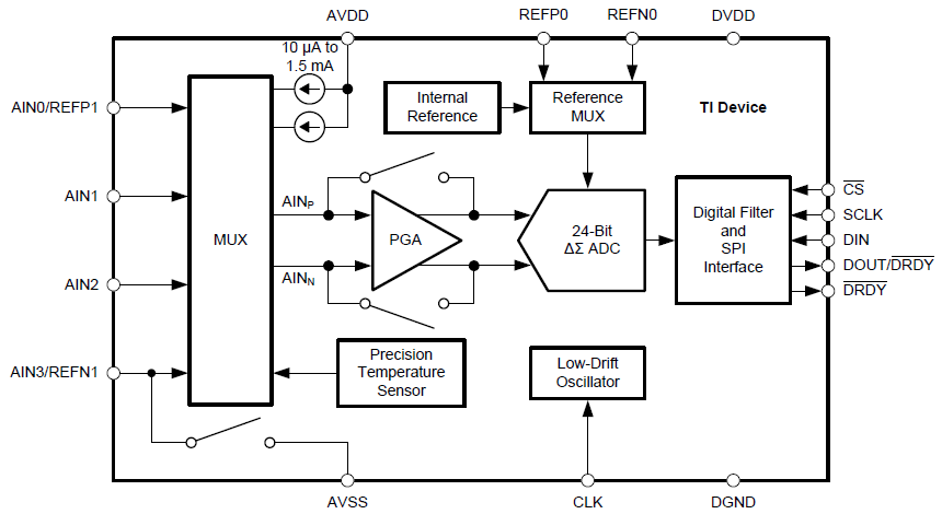
It comes with four single-ended input channels. These channels can also be set up to function as two differential input channels. One of the standout features of the ADS1220 chip is its low-noise programmable gain amplifier (PGA), which enhances its performance. Additionally, the chip provides flexibility in its operation, allowing users to choose between two conversion modes: continuous conversion or single-shot conversion. This versatility makes the ADS1220 chip a valuable tool for various applications.
Features of the ADS1220 Chip
- Analog power supply: 2.3 to 5.5 volts at AVDD / AVSS (AGND).
- Digital power supply: 2.3 to 5.5 volts at DVDD / DGND.
- Bipolar power supply option: e.g. AVSS to DGND = -2.5 volts, AVDD to DGND = +2.5 volts.
- Power consumption: 120 microamps in duty cycle mode.
- Communication: via SPI.
- Reference voltages:
- Internal: 2.048 volts.
- External: VREFPx – VREFNx = min. 0.75 volts, max. AVDD.
- Gain: 1 – 128 (with PGA = Programmable Gain Amplifier), 1 – 4 (without PGA).
- Data rate: 5 – 2000 SPS (Samples per Second)
- Conversion modes: Continuous and “Single-Shot” mode.
- Voltage inputs: 4 single-ended (against AVSS) or 2 differential inputs.
- Measurement in multiplex mode.
- Two programmable IDACs (digital-to-analog converter for current): 10 microamps to 1.5 milliamperes (also called “excitation current source” in the data sheet).
- Digital filter: 50 and/or 60 Hz.
- Integrated temperature sensor.
ADS1220 Functional Block Diagram
Recommended SPI Connection with Microcontroller
The ADS1220 can work with the SPI systems of most microcontrollers. It uses SPI mode 1, where CPOL is set to 0 and CPHA is set to 1. In this mode, SCLK stays low when idle. Data changes or starts only when SCLK goes up and is read or locked when SCLK goes down.

Texas Instruments (TI) suggests using 47-Ω resistors with all the digital input and output pins like CS, SCLK, DIN, DOUT/DRDY, and DRDY. These resistors help in making transitions smoother, controlling overshoot, and giving some protection against high voltage. However, when adding these resistors, it’s important to make sure all SPI timings are still met because the resistors can affect the digital signals due to bus capacitances.
ADS1220 Chip Package
The ADS1220 chip comes in two different integrated circuit packages, as illustrated in the provided figure.
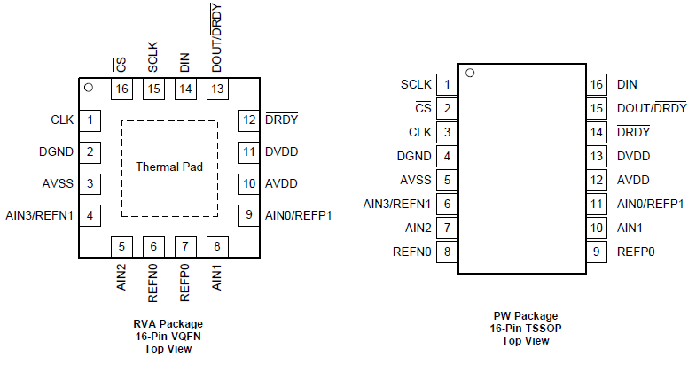
The first package is the 16-pin TSSOP (Thin Shrink Small Outline Package). This is the larger package, with a chip body measuring approximately 5.1mm x 4.5mm. The second package is the VQFN (Quad Flatpack No-Lead). This is a much more compact package, with a body dimension of just 3.6mm x 3.6mm. The choice between these packages depends on the specific requirements and space constraints of the project or application in which the chip will be used.
To learn more about the ADS1220 Chip, refer to the ADS1220 Datasheet.
ADS1220 Breakout Board
The ADS1220 chip comes in a very small package. That is, it is not available in a bigger DIP package that can be inserted on a breadboard.
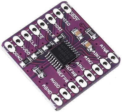
Therefore, for protyping and testing we need to use breakout Board or Module. There are many manufacturers of these boards such as Protocentral, Olimex and CJMCU. Out of these the CJMCU model is sold most.
ADS1220 Breakout Schematic
The image above shows the schematic for Protocentral’s ADS1220 ADC module.

While the CJMCU ADS1220 ADC modules have a similar design, there’s a small difference. The CJMCU versions use 24Ohms resistors for the SPI lines, unlike the 47Ohms resistors used by Protocentral.
ADS1220 Module Pinout
The ADS1220 Chip or the Breakout Board has a total of 18 pins.
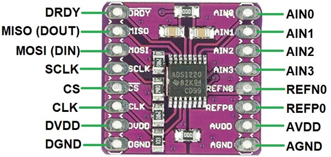
Here are the pin details with function.
| Pin Number | Pin Name | Description |
|---|---|---|
| 1 | DRDY | Data Ready Pin. Goes LOW when data is available for reading. |
| 2 | MISO (DOUT) | Master In Slave Out (MISO) pin. Also indicates when data is ready to be read. |
| 3 | MOSI (DIN) | Master Out Slave In (MOSI) pin. Used to send data from the master to the slave. |
| 4 | SCLK | Serial Clock (SCLK) pin. Provides synchronization for data transmission. |
| 5 | CS | Chip Select (CS) pin. Activates the slave device for communication. |
| 6 | CLK | Optional external clock input. |
| 7 | DVDD | Supply pin for digital voltage. |
| 8 | DGND | Ground pin for digital voltage. |
| 9 | AGND | Ground pin for analog voltage. |
| 10 | AVDD | Supply pin for analog voltage. |
| 11 | REFP0 | Positive pin for external reference voltage. |
| 12 | REFFN0 | Negative pin for external reference voltage. |
| 13 | AIN3 | Analog input for voltage measurement. Can also serve as a negative input for an external reference voltage. |
| 14 | AIN2 | Analog input for voltage measurement. |
| 15 | AIN1 | Analog input for voltage measurement. |
| 16 | AIN0 | Analog input for voltage measurement. Can also serve as a positive input for an external reference voltage. |
Interfacing ADS1220 24-Bit ADC Module with Arduino
Now let us learn how we can connect the ADS1220 24-Bit ADC Module with Arduino Nano Microcontroller Board. Here is a simple connection diagram.

This table provides a clear mapping of each ADS1220 Module pin to its corresponding Arduino pin.
| ADS1220 Module Pin | Arduino Pin |
|---|---|
| DRDY | D6 |
| MISO | D12 |
| MOSI | D11 |
| SCLK | D13 |
| CS | D7 |
| DVDD | +5V |
| DGND | GND |
| AGND | GND |
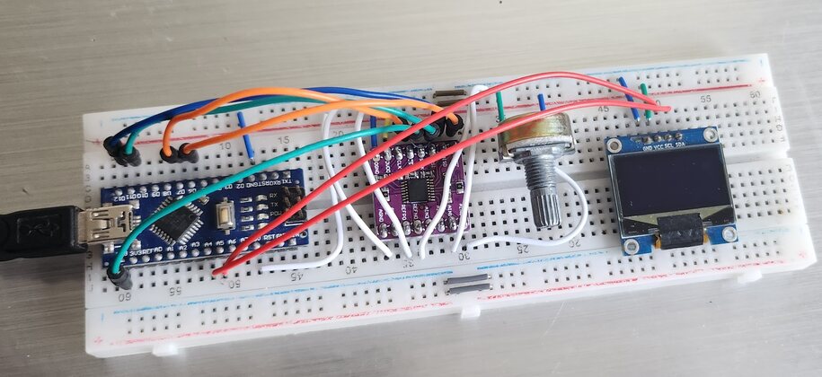
The Module can be easily assembled on a breadboard with Arduino Nano Board.
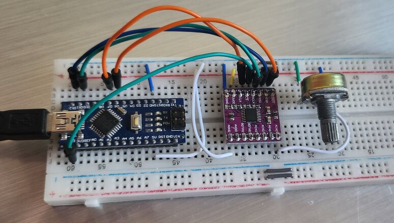
The analog input can be fed through AIN0, AIN1, AIN2 and AIN3 Pin. If you don’t have a Variable Power Supply Source, you may use a Potentiometer to fed the input voltage.
For demonstration I used a 10K potentiometer to fed analog voltage between 5V to 0V.
ADS1220 Arduino Library Installation & Usage
The Protocentral ADS1220 Arduino Library is designed to simplify the interfacing of the ADS1220 ADC module with Arduino boards. Here’s a detailed guide on its installation and usage:
Library Installation
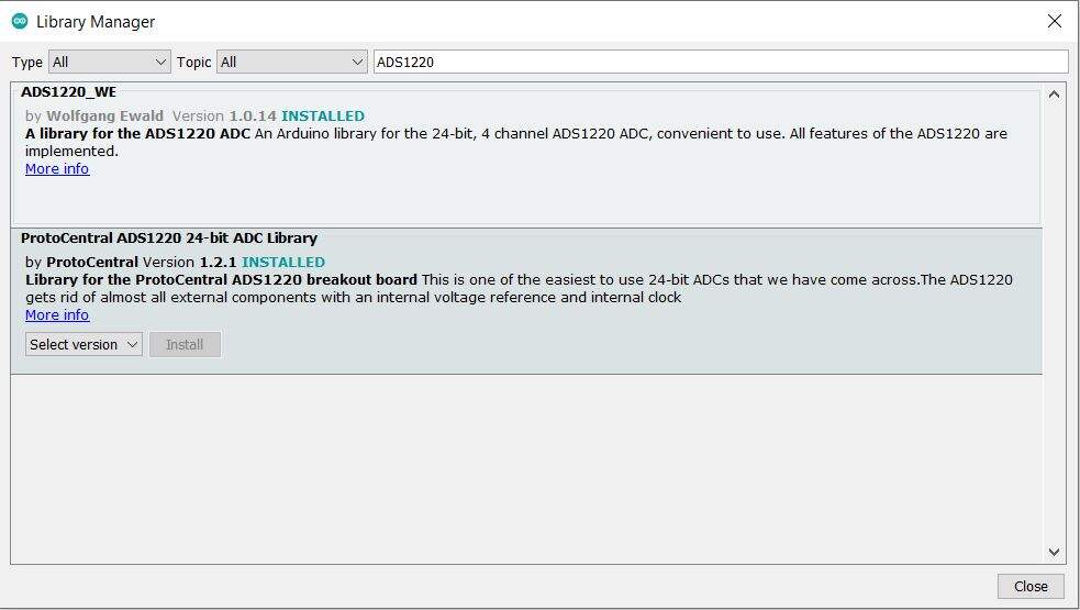
- Arduino IDE: You can install the Protocentral ADS1220 library directly from the Arduino IDE. Go to
Sketch>Include Library>Manage Libraries, then search for “Protocentral ADS1220” and install it.
- Manual Installation: Alternatively, you can download the library from GitHub or the Protocentral website and manually add it to your Arduino libraries folder.
Library Usage
1. Protocentral ADS1220 Library READ Methods:
The library provides methods to read data directly from the ADS1220 ADC module. The primary method is:
|
1 |
int32_t adc_data = ads1220.read_data(); |
This method fetches the ADC reading as a 32-bit signed integer, representing the raw ADC value. This value can then be converted to a voltage or used directly, depending on the application.
2. Conversion Mode:
The ADS1220 offers two primary modes of conversion:
- Continuous Mode: The ADC continuously converts the analog input to digital values. This mode is useful when constant monitoring is required.
|
1 |
ads1220.set_mode(MODE_CONTINUOUS); |
- Single-shot Mode: The ADC performs one conversion and then stops. This mode conserves power as the ADC isn’t constantly converting.
|
1 |
ads1220.set_mode(MODE_SINGLE_SHOT); |
3. Available READ Methods:
Apart from the primary read_data() method, the library provides methods to read specific configurations or status from the ADC. For instance, you might find methods to read calibration values, device ID, or other configuration settings.
4. The Programmable Gain Amplifier (PGA):
The ADS1220 features a built-in PGA, which amplifies the signal before conversion. This is especially useful for reading small voltage differences. The gain can be set using:
|
1 |
ads1220.set_gain(GAIN); |
Where GAIN can be values like 1, 2, 4, 8, 16, 32, 64, 128 depending on the library’s definitions. The gain directly affects the Full-Scale Range (FSR) of the ADC.
5. FSR and VREF (Voltage Reference):
- FSR (Full-Scale Range): Represents the range of voltages the ADC can read. It’s determined by the gain setting of the PGA and VREF. Mathematically, FSR can be calculated as:
FSR=VREF/Gain - VREF: The reference voltage against which the ADC performs conversions. The ADS1220 can use an internal or external VREF. The choice of VREF and the PGA setting together determine the ADC’s FSR.
It’s essential to note that the FSR values mentioned are accurate when using the internal voltage reference of the ADS1220, which is 2.048V. For example, if an external 5V reference is connected to the REFP0 and REFN0 pins and the gain setting remains at 1, the FSR becomes 5V. This means the ADC can measure voltages in the range of 0 to 5V.
6. Converting ADC Values to Voltage:
To convert the raw ADC output to a voltage reading, use the formula:
Where:
- n is the raw ADC value returned by the read command.
- VREF is the voltage reference, typically 2.048V for ADS1220.
- Gain is the setting of the Programmable Gain Amplifier (PGA).
The divisor, 8,388,607, represents the resolution of the ADC, which is (2^23)−1 due to the 24-bit ADC of the ADS1220 reserving one bit for polarity.
7. Changing the Data Rate:
The data rate, or how fast the ADC performs conversions, can be adjusted. A higher data rate might lead to faster conversions but could introduce more noise. Conversely, a lower data rate might be more accurate but slower. You can set the desired data rate using:
|
1 |
ads1220.set_data_rate(DR); |
Where DR is the desired data rate value, like 20SPS, 45SPS, 90SPS, 175SPS etc.
Test Code: Read voltage values from 4 channels of ADS1220
The primary purpose of this code is to read voltage values from the four channels of the ADS1220 ADC module and display them in millivolts on the serial monitor.
The ADC operates in single-shot mode, meaning it performs one conversion at a time upon request. The readings from the ADC are taken at regular intervals (due to the delay(100)), and the results are printed to the serial monitor for each channel.
|
1 2 3 4 5 6 7 8 9 10 11 12 13 14 15 16 17 18 19 20 21 22 23 24 25 26 27 28 29 30 31 32 33 34 35 36 37 38 39 40 41 42 43 44 45 46 47 48 49 50 51 52 53 54 55 56 57 58 59 60 61 62 63 |
#include "Protocentral_ADS1220.h" #include <SPI.h> #define PGA 1 // Programmable Gain = 1 #define VREF 2.048 // Internal reference of 2.048V #define VFSR VREF/PGA #define FULL_SCALE (((long int)1<<23)-1) #define ADS1220_CS_PIN 7 #define ADS1220_DRDY_PIN 6 Protocentral_ADS1220 pc_ads1220; int32_t adc_data; volatile bool drdyIntrFlag = false; void drdyInterruptHndlr(){ drdyIntrFlag = true; } void enableInterruptPin(){ attachInterrupt(digitalPinToInterrupt(ADS1220_DRDY_PIN), drdyInterruptHndlr, FALLING); } void setup() { Serial.begin(9600); pc_ads1220.begin(ADS1220_CS_PIN,ADS1220_DRDY_PIN); pc_ads1220.set_data_rate(DR_330SPS); pc_ads1220.set_pga_gain(PGA_GAIN_1); pc_ads1220.set_conv_mode_single_shot(); //Set Single shot mode } void loop() { adc_data=pc_ads1220.Read_SingleShot_SingleEnded_WaitForData(MUX_SE_CH0); Serial.print("\n\nCh1 (mV): "); Serial.print(convertToMilliV(adc_data)); delay(100); adc_data=pc_ads1220.Read_SingleShot_SingleEnded_WaitForData(MUX_SE_CH1); Serial.print("\nCh2 (mV): "); Serial.print(convertToMilliV(adc_data)); delay(100); adc_data=pc_ads1220.Read_SingleShot_SingleEnded_WaitForData(MUX_SE_CH2); Serial.print("\nCh3 (mV): "); Serial.print(convertToMilliV(adc_data)); delay(100); adc_data=pc_ads1220.Read_SingleShot_SingleEnded_WaitForData(MUX_SE_CH3); Serial.print("\nCh4 (mV): "); Serial.print(convertToMilliV(adc_data)); delay(100); } float convertToMilliV(int32_t i32data) { return (float)((i32data*VFSR*1000)/FULL_SCALE); } |
After uploading the code, open your Serial Monitor.
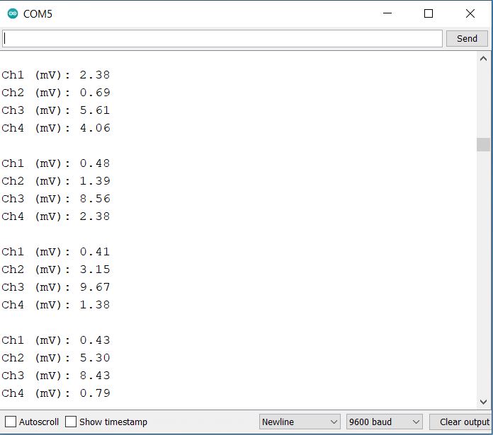
As you can see, all the 4 outputs are identical. This is becasue I wired all the input channels to a single voltage. To observe the variation in voltage you may supply a variable input at any of the input terminal from AIN0, AIN1, AIN2, AIN3.
Making 0-5V Precision Voltmeter with exernal Reference Voltage
Now lets use the external reference voltage to make a low-cost precision voltmeter. This can measure the voltage in millivolt and upto a decimal point of 5. Thus this can be used to make a Milli/Micro Voltmeter.
Hardware Setup
Here is the hardware setup. I have changed the connection between Arduino & 24-Bit ADC Module ADS1220 as per the requirements. To visualize the voltage, I have used a 0.96″ I2C OLED Display.

Here is a connection details of ADS1220 Pin with Arduino and ADS1220.
| ADS1220 Pin | Arduino Pin |
|---|---|
| DRDY | D6 |
| MISO | D12 |
| MOSI | D11 |
| SCLK | D13 |
| CS | D7 |
| DVDD | 5V |
| DGND | GND |
| AGND | GND |
| REFP0 | 5V |
| REFN0 | GND |
| AIN1 | GND |
Similalry the AIN0 pin is connected to the middle pin of 10K Potentiometer. This is optional as 10K Potentiometer is not needed. We are using this potentiometer to supply input voltage. You may use any other source to fed the input voltage via AIN0 Pin of ADS1220.
To visualize the read voltage, we can use 0.96″ I2C OLED Display module. The OLED Display can be connected to I2C Pin of Arduino Nano.
Source Code/Program
The following is the code for building a low-cost precision voltmeter.
The code requires some of the libraries that need to be added in Arduino Library Folder.
Here is a complete code for the project part. You need to adjust your External reference input (VREF) for precise and correct measurement.
|
1 2 3 4 5 6 7 8 9 10 11 12 13 14 15 16 17 18 19 20 21 22 23 24 25 26 27 28 29 30 31 32 33 34 35 36 37 38 39 40 41 42 43 44 45 46 47 48 49 50 51 52 53 54 55 56 57 58 59 60 61 62 63 64 65 66 67 68 69 70 |
#include <Wire.h> #include <SPI.h> #include <Adafruit_SSD1306.h> #include <Adafruit_GFX.h> #include "MegunoLink.h" #include "Filter.h" #include "Protocentral_ADS1220.h" #define OLED_WIDTH 128 #define OLED_HEIGHT 64 #define OLED_ADDR 0x3C #define PGA 1 // Programmable Gain = 1 #define VREF 4.72 // External reference input #define VFSR VREF/PGA #define FULL_SCALE (((long int)1<<23)-1) #define ADS1220_CS_PIN 7 #define ADS1220_DRDY_PIN 6 Adafruit_SSD1306 display(OLED_WIDTH, OLED_HEIGHT); Protocentral_ADS1220 pc_ads1220; ExponentialFilter<float> FilteredV(20, 0); int32_t adc_data; void setup() { Serial.begin(115200); display.begin(SSD1306_SWITCHCAPVCC, OLED_ADDR); display.clearDisplay(); pc_ads1220.begin(ADS1220_CS_PIN, ADS1220_DRDY_PIN); pc_ads1220.writeRegister(CONFIG_REG2_ADDRESS, 0x40); pc_ads1220.set_data_rate(DR_20SPS); pc_ads1220.set_pga_gain(PGA_GAIN_1); pc_ads1220.PGA_OFF(); pc_ads1220.set_conv_mode_single_shot(); // Set Single shot mode display.display(); } void loop() { adc_data = pc_ads1220.Read_SingleShot_SingleEnded_WaitForData(MUX_AIN0_AIN1); float mv = convertToVolt(adc_data); FilteredV.Filter(mv); float SmoothV = FilteredV.Current(); Serial.print("Measured Voltage: "); Serial.print(SmoothV); Serial.println("mV"); delay(5); display.clearDisplay(); display.setTextSize(3); display.setTextColor(WHITE); display.setCursor(0, 20); display.println(SmoothV/10000, 5); display.setTextSize(1); display.setTextColor(WHITE); display.setCursor(0, 0); display.println("Output Voltage (mV):"); display.display(); } float convertToVolt(int32_t i32data) { return (float)((i32data * VFSR * 10000) / FULL_SCALE); } |
Before diving into voltage measurements, it’s essential to understand its capabilities. The IC has a default internal reference of 2.048 V, which means it can measure up to this voltage. However, the ADS1220 allows for an external voltage reference, supporting up to 7.3 volts (with AVDD set to 7 V). For optimal results, I connected a 5-volt supply from the Arduino to the ADS1220’s reference input. To ensure accurate readings, it’s recommended to use an external voltage reference IC, like the REF5050, as relying on the Arduino’s power rails might introduce noise and inconsistencies.
For my setup, I utilized channel-1 of the ADS1220, with the AIN0 pin grounded and the AIN1 pin connected to a variable PSU. If you observe any measurement discrepancies, consider adjusting the VREF value in your code. Such variations can result from unstable reference sources or unwanted resistances. With these insights, you’re well-prepared to harness the full potential of your new voltmeter!
Testing & Results
Our voltmeter is designed to give you super accurate readings, showing up to five decimal places.
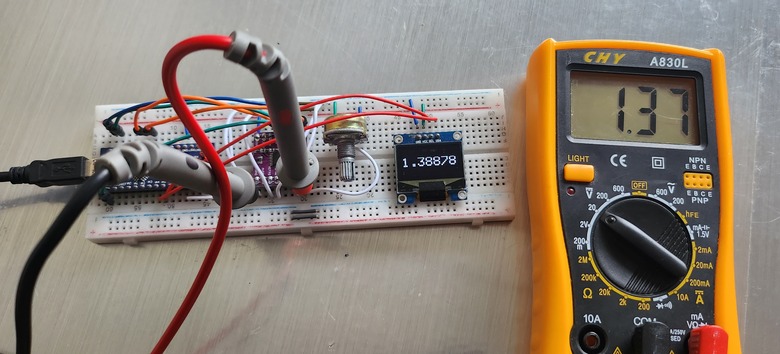
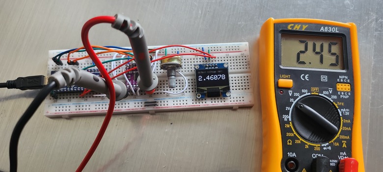
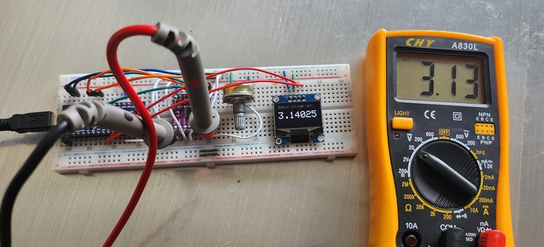
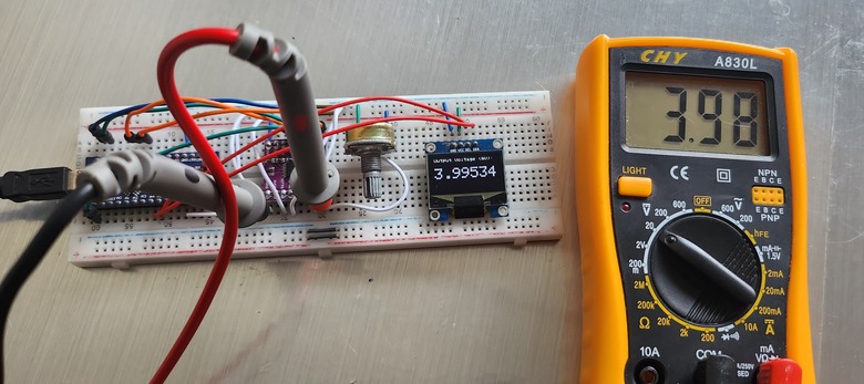
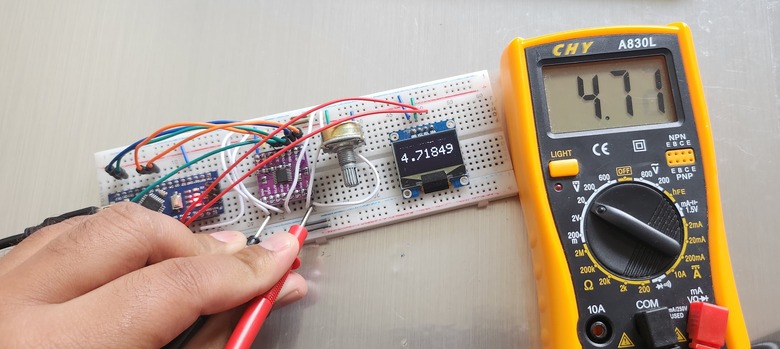
To get the most accurate results, make sure you set the right external reference voltage in the code’s VREF variable. If you can, double-check your readings with a reliable multimeter. If needed, you can calibrate your meter using the steps mentioned earlier. With a bit of care and attention, you’ll have a top-notch voltmeter made right at home.
Conclusion
In conclusion, the ADS1220 24-bit ADC Module stands out as a superior choice for those seeking precision in voltage measurements. When integrated with platforms like Arduino, it significantly enhances the capability to detect minute voltage differences, far surpassing the built-in 10-bit ADC of standard Arduino boards. The ADS1220’s ability to measure as fine as 0.3uV, compared to Arduino’s 4.9mV, underscores its remarkable precision.
Furthermore, our testing with the voltmeter, which displays readings up to five decimal places, reaffirms the ADS1220’s promise of delivering unparalleled accuracy. For anyone prioritizing precision in their projects, the ADS1220 24-bit ADC Module is undoubtedly a top recommendation.

")


