

Overview: Programming ESP8266 Raw Chip
In this article, we will go through how to program the raw ESP8266 (ESP8266-12E/F) chip as well as the accompanying circuit that allows the chip to function in real-time applications. We shall see the ESP8266 Programmer Circuit & PCB at the end of this article, which is very tiny & compact for real-time projects.
The NodeMCU is well-known among electronics amateurs and IoT specialists alike. NodeMCU is the first development board that springs to mind when one has to prototype something that involves WiFi. Using the NodeMCU board during the prototype process is the best solution. However, when the prototype and testing phases are completed, employing the entire NodeMCU board in the project’s PCB is not a wise idea. One requires the ESP8266-12E/F raw chip and not the entire development board, which is meant for newcomers to work easily on.
Using the raw ESP8266-12E/F chip reduces the cost of the project and increases the robustness. We can easily program this raw chip with an external programmer by hooking up a few wires to the custom PCB. So let us learn to program Raw ESP8266 Chip using Arduino IDE
Bill of Materials
To make this project work on a breadboard, you will need the following supplies.
| S.No. | Components | Quantity |
|---|---|---|
| 1 | ESP-12E/F | 1 |
| 2 | 10K / 12K ohm resistors | 5 |
| 3 | 22K ohm resistor | 2 |
| 4 | 330 ohm resistor | 1 |
| 5 | 470PF capacitor | 1 |
| 6 | 0.1 micro F capacitor | 1 |
| 7 | NPN transistor (BC547) | 2 |
| 8 | Push Buttons | 2 |
| 9 | Single strand hookup wire | |
| 10 | Jumper wires | |
| 11 | FDTI converter (USB to UART bridge) | 1 |
Traditionally way of using NodeMCU
During the prototyping phase of the project, we develop the firmware either in Arduino IDE or the Platform IO and upload the firmware by plugging the USB jack into the NodeMCU and selecting the appropriate port and board in the Arduino IDE or Platform IO (in Platform IO, it automatically detects the port, you can also choose the port by configuring the upload options in platfomio.ini, for more upload options).
Firmware is loaded onto the chip using a USB to UART bridge built in the NodeMCU. The chip should be reset in flash mode before flashing the firmware, and the inbuilt USB to UART bridge translates the USB data into UART format and communicates with the device through RXD0 and TXD0 pins. This is all handled automatically by the supporting circuit built on the NodeMCU.
When the auto-loading fails, additional Flash and Reset pins are given to restart the NodeMCU in flash mode.
Programming Raw ESP8266 Chip
Let’s look through the raw chip’s physical characteristics and specs. This is a necessary step before learning how to program the ESP8266 chip.

Pin configurations
The ESP-12E module has 22 pins; let’s look at what each one does.
| Pin | Name | Description |
|---|---|---|
| 1 | RST | Reset Pin of the module |
| 2 | ADC | Analog Input Pin for 10-bit ADC (0V to1V) |
| 3 | EN | Module Enable Pin (Active HIGH) |
| 4,5,6,7,11,12, 16, 17, 18, 19, 20 | GPIO16, GPIO14, GPIO12, GPIO13, GPIO9, GPIO10, GPIO15, GPIO2, GPIO0, GPIO4, GPIO5 | General Purpose Input Output Pins |
| 8 | VDD | +3.3V Power Input |
| 9 | CS0 | Chip selection Pin of SPI interface |
| 10 | MISO | MISO Pin of SPI interface |
| 13 | MOSI | MOSI Pin of SPI interface |
| 14 | SCLK | Clock Pin of SPI interface |
| 15 | GND | Ground Pin |
| 21 | RXD0 | UART0 RXD Pin |
| 22 | TXD0 | UART0 TXD Pin |
To program the raw chip, we must have access to its pins and a thorough understanding of the chip’s operation, booting, and flashing processes.

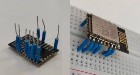
The physical dimensions of the module are 16mm × 24mm × 3mm, and the lead pitch is 2mm. But the lead pitch of the breadboard is 2.54mm (0.1 inc). To make this chip breadboard-friendly I have soldered the single strand hookup wires to the chip.
Different booting modes
| Booting options | Enable pin (EN) | GPIO0 | GPIO2 | GPIO15 |
|---|---|---|---|---|
| Programming Mode | High | Low | High | Low |
| Flash start-up (normal mode) | High | High | High | Low |
| SD card boot-up | High | Low | Low | High |
We can reboot the ESP8266-12E/F in multiple booting modes by pulling up or down on specific GPIOs. In order to upload the firmware, we should first boot the chip in programming mode. The chip should boot in flash start-up mode during regular modes. As a result, we’re just interested in the first two booting modes.
In both working modes, the enable(EN) and GPIO2 pins are HIGH, while the GPIO15 pin is LOW, as shown in the table above. So, pull up the enable (EN), GPIO2, and pull down the GPIO15 pin with 10K/12K ohm resistors. The reset pin and GPIO0 pin are normally held high and connected to the ground with push buttons.

Flashing process
Let us see how we can Program ESP8266 Chip. First Power on the circuit by pressing the push button of the GPIO0 and release this pushbutton after the chip boots up. Now the chip is booted in the programming mode.
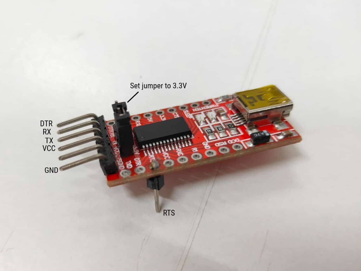
Now take any USB to the UART bridge (FT232RL recommended) and connect the RX and TX pins of FT232RL to the TXD0 and RXD0 pins of the chip, also make sure that the jumper on the FT232RL module is toggled to 3.3V.
Connect the FT232RL to the computer and upload the firmware. Following are the upload options that you need to follow while uploading the firmware using Arduino. Select the board type as generic esp8266 module, upload speed as 115200, and choose the correct port. With platform IO, selecting the board option as Espressif ESP8266 ESPf-12E will work.
After completion of the flashing, restart the chip by pressing the reset push button to boot in normal mode.
This process requires manual intervention like pressing the push button and reset button. To this manual interventions and flash the firmware into the chip seamlessly as we do with the NodeMCU we need to use the DTR (Data Terminal Ready) and RTS (Ready to Send) signals of the FT232RL USB to UART bridge.
The RTS pin of the FT232RL module is located at a different place where you need to solder the male header to access that pin.
Automatic flashing
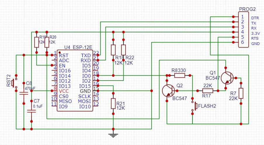
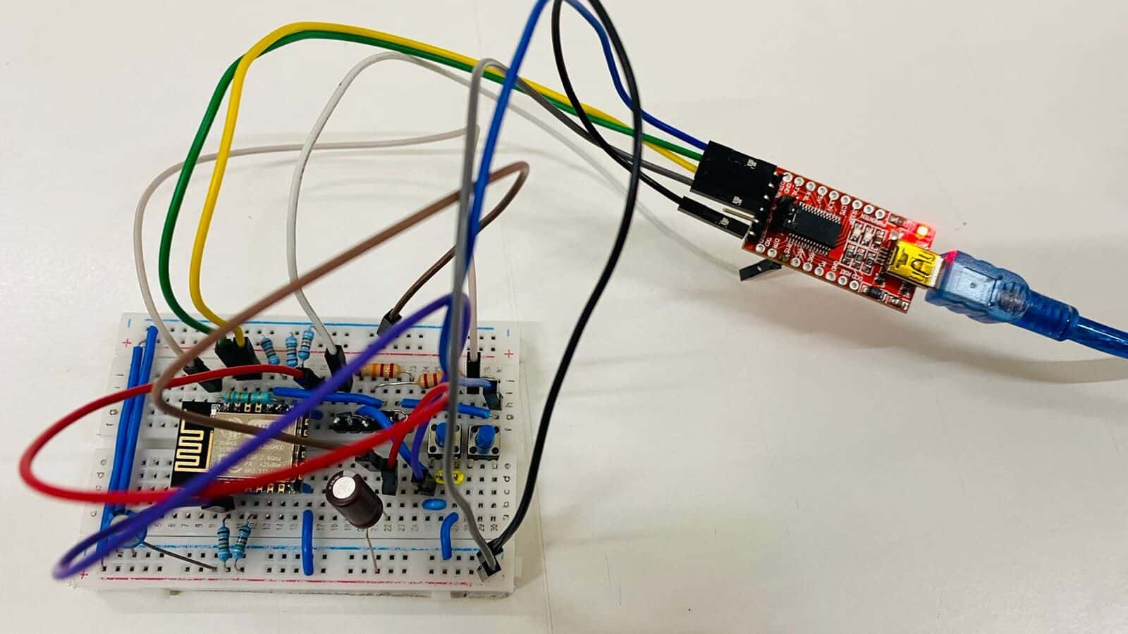
The ESP8266 Programmer Circuit or the automatic flashing circuit is almost similar to the manual flashing circuit with some additional transistor circuit that deals with the DTR and RTS pins of FT232RL.
RTS signal is used for resetting the chip and the DTR signal is used for keeping the chip in flash mode. Transistors(BC547) Q1 and Q2 are used to keep the chip in flash mode when the upload command is detected and a new sketch can be uploaded to it seamlessly.
These transistors also ensure that the chip doesn’t reset when the DTR and RTS signals are low, and also start the chip in the normal mode (Flash start-up) in the absence of upload command.
At the time of writing this article, I had the BC547 NPN transistor and 470pF capacitor in an SMD package. As a result, I attached these components to the male headers to make it breadboard compatible.
![]()
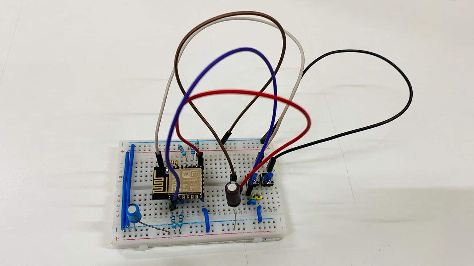
Complete the wiring as shown in the schematic and connect the RTS, DTR, RX, TX, VCC, and GND pins of the FT232RL to the appropriate pins of the chip. Also, make sure that the jumper on the FT232RL module is set to 3.3V.
After making connections, connect the FT232RL module to the compute and follow the upload options as discussed earlier. Now you can find that the firmware is flashed seamlessly without manual intervention. We can also use the two pushbuttons (reset and flash) to upload the firmware when the autoloading/auto flashing firmware fails.
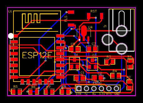
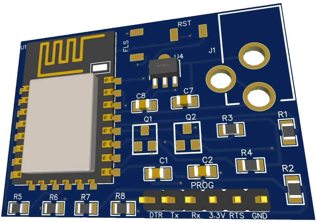
Compact PCB for the Autoflashing circuit
If you want a compact ESP8266-12E/F programmer with the power supply to it and access to a few GPIOs of the chip, then here is the PCB for you. This ESP8266 Programmer Circuit PCB is designed in the EasyEDA. The following figure is the schematic footprint of the circuit.
The Gerber File for the PCB is given below. You can simply download the Gerber File and order the PCB from ALLPCB at 1$ only.
You can use this Gerber file to order high quality PCB for this project. To do that visit the ALLPCB official website by clicking here: https://www.allpcb.com/.

You can now upload the Gerber File by choosing the Quote Now option. From these options, you can choose the Material Type, Dimensions, Quantity, Thickness, Solder Mask Color and other required parameters.

After filling all details, select your country and shipping method. Finally you can place the order.
You can assemble the components on the PCB Board.
You can also add some Battery charging IC and add some active-passive components to make your Battery Powered ESP8266 Board for IoT applications.


")

