

Overview
In this project, we will build an IoT-enabled Smart Fridge with ESP8266 Microcontroller & multiple DS18B20 temperature sensors. With the advancement of the Internet of Things, devices are getting smarter and data collection can help make daily life easier. The Internet of Things (IoT)-enabled smart fridges or refrigerators are intelligent appliances that offer temperature optimization, diagnostics, and data collection features. This can maximize food storage and reduce product deterioration. It also provides owners with a more practical and efficient approach to overseeing their food storage.
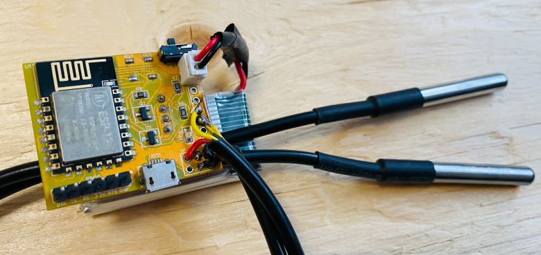
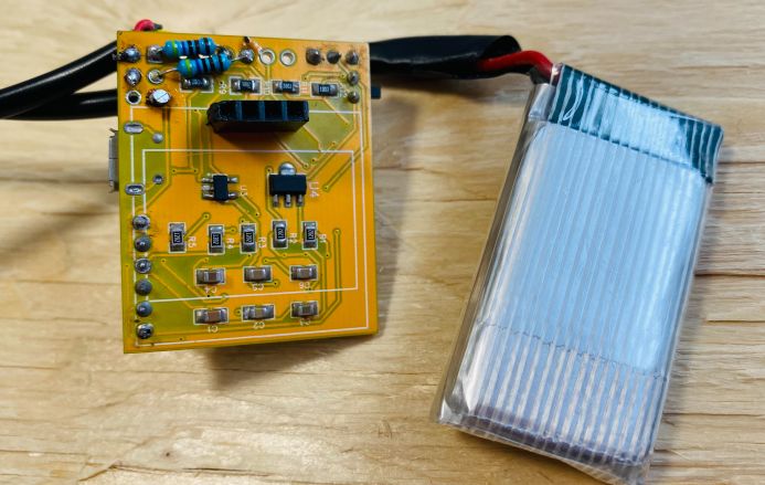
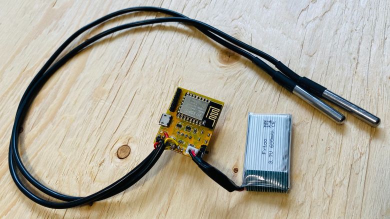
In this project, we have built a tiny battery-powered smart device using the ESP8266 WiFi Module and a pair of DS18B20 Temperature Sensors. The device has very low power LDO to operate at lower temperatures. It also has a BMS IC to charge, manage, and protect the battery. Due to its tiny size, it can be put anywhere and requires very small space.

Regarding the data observations parts, the ESP8266 connects to a Wi-Fi network and generates a webpage. The webpage can be accessed from any Web Browser. The wepage displays the value of Battery Voltage, Battery Percentage, Fridge Temperature, and Freezer Temperature. The Web page is AJAX-based, hence data is updated without refreshing the webpage.
Bill of Materials
The following is the Bill of Materials for IoT-enabled Smart Fridge. Most of the components used here are SMD Components.
| ID | Name | Designator | Footprint | Quantity | Manufacturer Part |
|---|---|---|---|---|---|
| 1 | Capacitor 1uF | C3 | C0805 | 1 | |
| 2 | Capacitor 47uF | C8 | Electrolytic 47UF 16V | 1 | |
| 3 | Capacitor 10uF | C4 | C0805 | 1 | |
| 4 | Capacitor 4.7uF | C5,C6 | C0805 | 2 | |
| 5 | Capacitor 22uF | C9 | Electrolytic 22UF 16V | 1 | |
| 6 | Capacitor 0.1uF | C1 | C0805 | 1 | |
| 7 | Capacitor 470pF | C2 | C0805 | 1 | |
| 8 | Resistor 330E | R6 | R0805 | 1 | |
| 9 | Resistor 470E | R9 | R0805 | 1 | |
| 10 | Resistor 12K | R1,R2,R3,R4,R5 | R0805 | 5 | |
| 11 | Resistor 20K | R11 | R0805 | 1 | |
| 12 | Resistor 2K | R10 | R0805 | 1 | |
| 13 | Resistor 22K | R8,R7 | R0805 | 2 | |
| 14 | Resistor 4.7K | R13 | R0805 | 1 | |
| 15 | Resistor 100K | R12 | R0805 | 1 | |
| 16 | LED | LED | LED0805-RD_RED | 1 | |
| 17 | ESP-12E | U1 | WIFIM-SMD_ESP-12E | 1 | ESP-12E |
| 18 | 0.96" OLED Display | U2 | 0.96 OLED | 1 | 0.96 OLED |
| 19 | HT7333 LDO | U4 | SOT-89-3_L4.5-W2.5-P1.50-LS4.2-BR | 1 | HT7333-7 |
| 20 | MCP73831 BMS IC | U3 | SOT-23-5 | 1 | MCP73831T-2ATI/OT |
| 21 | DS18B20 Sensors | U5,U6 | DS18B20 | 2 | DS18B20 |
| 22 | Male Heades 1x6 | PROG | HDR-TH_6P-P2.54-V-M-1 | 1 | Header-Male-2.54_1x6 |
| 23 | Slide Switch | SW1 | SW-TH_MK-12D18-G040 | 1 | MK-12D18-G020 |
| 24 | Transistor BC847 | Q1,Q2 | SOT-23-3_L2.9-W1.4-P1.90-LS2.6-BR | 2 | BC847A 1E |
| 25 | MICRO USB | USB1 | MICRO-USB-SMD_MICRO-09-GXPX-A2T2 | 1 | MICRO-09-G2P1-A2T2 |
| 26 | Push Button Switch | FLS,RST | SW-SMD_L4.0-W3.0-LS4.8 | 2 | TS-1071AS-A1B3-D4 |
| 27 | Battery Connector | CN1 | BATTERY CONNECTOR | 1 | |
| 28 | 3.7V Lithium-Ion Battery | CN1 | 1 |
Hardware Design for IoT-enabled Smart Fridge
The schematic we’re looking at is for an IoT-enabled Smart Fridge with ESP8266 that runs on battery power.
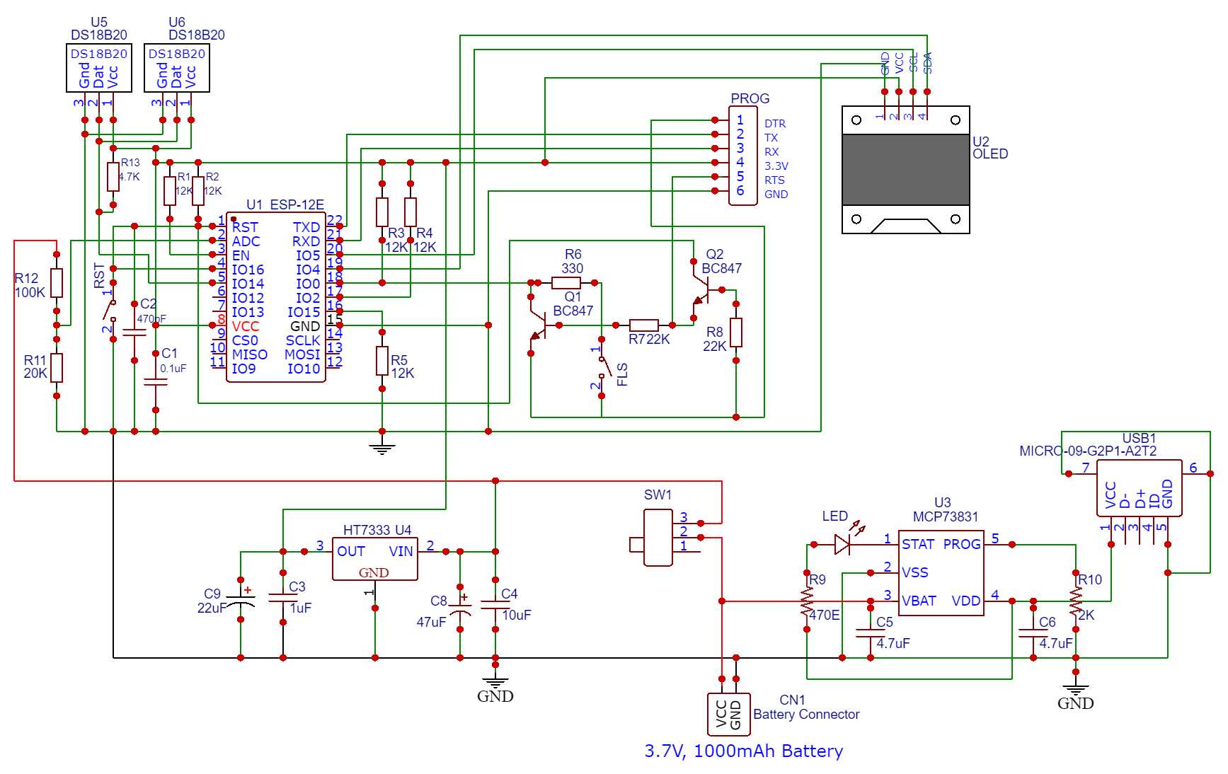
We use the raw ESP8266 chip, specifically the ESP8266-12E/12F variant. The setup includes a low-power LDO, a battery management IC, and a USB port for battery charging, connectors for DS1B20 Temperature Sensors. There’s also a switch for powering the system on and off.
BMS & Charging IC MCP73831
Given that the device operates on battery power, it necessitates regular battery charging and management, a task handled by the MCP73831 IC.

The MCP73831 IC devices are sophisticated linear charge management controllers suitable for applications with space limitations and cost concerns. They utilize a constant-current/constant-voltage charge algorithm, featuring selectable preconditioning and charge termination.
You can follow the MCP73831 Application Circuit for more about the IC.
Voltage Regulator & LDO HT7333
Many ESP8266-based boards come with voltage regulators like the AMS117, which has a voltage drop-out of 1.3V. This voltage drop-out is too significant for ESP boards powered by batteries.

Thus, a preferable alternative is the HT7333 3.3V Linear Voltage Regulator IC, which has a drop-out of just 170mV and an exceptionally low quiescent current of 8uA. This makes it ideal for battery-powered applications. The IC receives input from the battery and delivers a regulated 3.3V output to the whole circuit, including the ESP8266 chip.
DS18B20 Waterproof Temperature Sensors
This is a pre-wired and waterproofed version of the DS18B20 sensor. Handy for when you need to measure something far away, or in wet conditions. The Sensor can measure the temperature between -55 to 125°C (-67°F to +257°F). These 1-wire digital temperature sensors are fairly precise, i.e ±0.5°C over much of the range. It can give up to 12 bits of precision from the onboard digital-to-analog converter. They work great with any microcontroller using a single digital pin.

The only downside is they use the Dallas 1-Wire protocol, which is somewhat complex and requires a bunch of code to parse out the communication. We toss in a 4.7k resistor, which is required as a pullup from the DATA to the VCC line when using the sensor. To learn more about this sensor you may refer to DS18B20 Arduino guide.
In this project, we are using two DS18B20 Temperature sensors as we will be measuring the internal temperature of fridge. One of the sensor is placed in fridge and other in the freezer. The sensor is connected to GPIO14 pin of the ESP8266.
ESP8266 Programmer Circuit
The discussed circuit comes equipped with an automatic programmer, eliminating the need for manual programming or the operation of push buttons. All it requires is an FTDI Module to program the raw ESP chip. The programming process is managed by two switches (FLS and RST), two BC547 transistors (Q1 and Q2), among other components.

The RTS signal is utilized for resetting the ESP8266, and the DTR signal puts the chip into flash mode. Transistors Q1 and Q2 ensure that the ESP8266 doesn’t reset when both DTR and RTS signals are low. When an upload command is detected, the ESP module automatically enters flash mode, facilitating the smooth upload of a new sketch. Without an upload command, the ESP-12E/F operates in normal mode, allowing the programmed ESP-12E/F board to be tested or deployed in an application.
Voltage Divider Network & ESP8266 ADC
The Battery Maximum voltage is 4.2V and the cut of voltage is 2.8V. The ESP8266 chip features a single analog pin with an input voltage range from 0 to 1V. Anything lesser than 1V will be easily supported by ESP8266 Analog Pin.

To manage voltages beyond this range, a voltage divider network, created by the R11(20K) and R12(100K) resistors, steps down the voltage. Consequently, in the above circuit, the battery’s output voltage is linked to the ESP8266 chip’s ADC (Analog-to-Digital Converter). Using some mathematical calculation, we can convert the ADC value into real voltage.
OLED Display (Optional)
The OLED Display is optional for this ESP8266 Based IoT Smart Fridge project. The OLED Display can be used for displaying Battery Charge, Voltage and DS18B20 Temperatures. We can use a 0.96″ I2C SSD1306 OLED Display or any other low Power display unit.
Project PCB Design, Gerber File & PCB Ordering Online
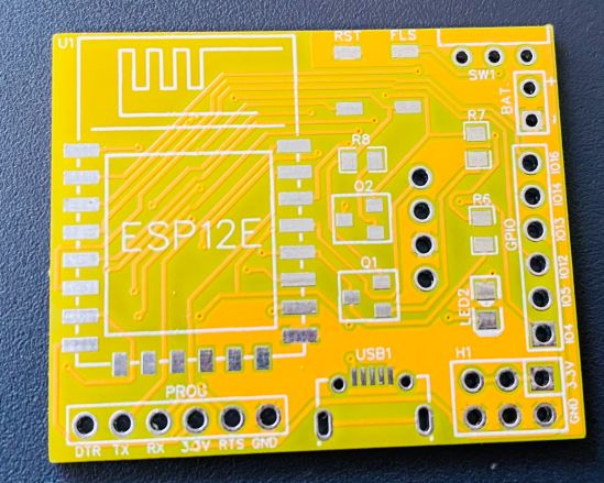
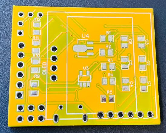
We have designed the PCB using the EasyEDA Software. It took quite a lot of time fixing all the issues in the PCB but still we managed to design a complete working custom PCB. The PCB design looks like this.
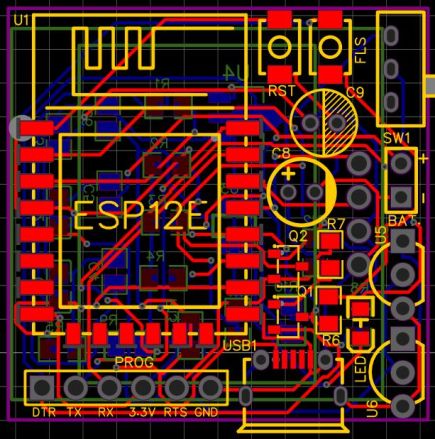
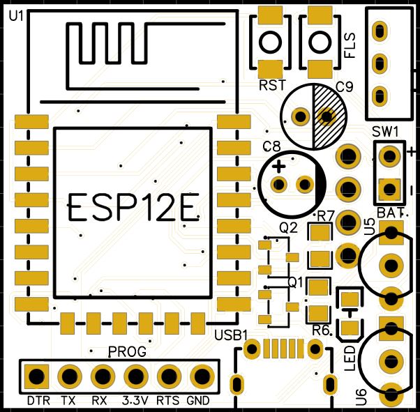
The PCB has SMD components with resistors, capacitors, and LED with an SMD package of 0805. The transistors, and push buttons are also in the SMD package. The components need to be mounted on both the front and back side of the PCB.
The Gerber File for the PCB is given below. You can simply download the Gerber File and order the PCB from PCBGOGO at 1$ only.
You can use this Gerber file to order high-quality PCB for this project. To do that visit the PCBGOGO official website by clicking here: https://www.pcbgogo.com/.

You can now upload the Gerber File by choosing the Quote Now option. From these options, you can choose the Material Type, Dimensions, Quantity, Thickness, Solder Mask Color and other required parameters.

After filling all details, select your country and shipping method. Finally you can place the order.
PCB & Hardware Assembly
After ordering the PCB, it took almost 5 days and I got my PCB.

The PCB quality from PCBGOGO is superb with very high quality. That is why most people trust PCBGOGO for PCB/PCBA Services.
On the front side, first solder all the SMD components like resistors, capacitors, transistors, LED & push buttons. Be careful about the SMD LED polarity, place it in the proper direction. After soldering all these, you can solder the ESP8266 raw chip.
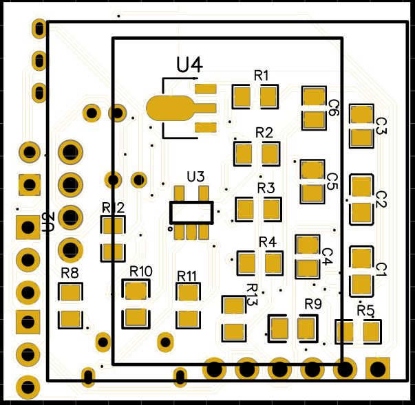
On the backside solder the resistors, capacitors, HT7333 and MCP73831 ICs. Also solder all the through-hole components. Using the wires and connectors solder the DS1B20 Sensor.
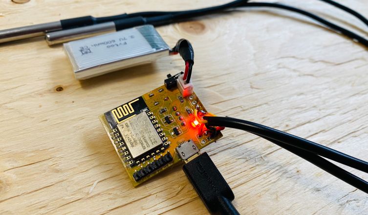
After soldering all the components, the IoT-enabled Smart Fridge with ESP8266 is ready for the test. You can upload a blink sketch by connecting a USB-to-TTL Converter Module.
The board has battery charging module called MCP73831. You may insert a micro-USB cable in the USB port to charge the battery.
Note: There were some voltage fluctuation issues in the designed PCB, so I have updated the design by adding some large capacitors. Also, some connection issues have been fixed. The Gerber file above is updated and the PCB would look something different from the above.
Source Code/Program
The code for the IoT-enabled Smart Fridge with ESP8266 WebServer is written in Arduino IDE.
This code sets up a smart Fridge using an ESP8266 microcontroller. It connects to a Wi-Fi network, reads temperature data from two DS18B20 sensors, and monitors battery voltage to calculate the battery percentage. The microcontroller hosts a web server that displays the battery voltage, battery percentage, and temperatures of the fridge and freezer on a stylized webpage.
It also provides an API endpoint (/data) that returns this data in JSON format. The webpage automatically updates the displayed data every 2 seconds by fetching the latest readings from the microcontroller. The code includes error handling for data fetching and uses animations for a visually appealing presentation of the sensor data on the webpage.
The code requires Dallas Temperature Library as well as OneWire Library for compilation. Add these libraries to Arduino Library folder before compiling.
From the following lines, change the WiFi SSID and Password.
|
1 2 3 |
// WiFi credentials const char* ssid = "**********"; const char* password = "**********"; |
Here is the complete code for the project. Copy the code and upload it to the ESP8266 Board.
|
1 2 3 4 5 6 7 8 9 10 11 12 13 14 15 16 17 18 19 20 21 22 23 24 25 26 27 28 29 30 31 32 33 34 35 36 37 38 39 40 41 42 43 44 45 46 47 48 49 50 51 52 53 54 55 56 57 58 59 60 61 62 63 64 65 66 67 68 69 70 71 72 73 74 75 76 77 78 79 80 81 82 83 84 85 86 87 88 89 90 91 92 93 94 95 96 97 98 99 100 101 102 103 104 105 106 107 108 109 110 111 112 113 114 115 116 117 118 119 120 121 122 123 124 125 126 127 128 129 130 131 132 133 134 135 136 137 138 139 140 141 142 143 144 145 146 147 148 149 150 151 152 153 154 155 156 157 158 159 |
#include <ESP8266WiFi.h> #include <ESP8266WebServer.h> #include <OneWire.h> #include <DallasTemperature.h> // Data wire is connected to GPIO5 #define ONE_WIRE_BUS 5 // Setup a oneWire instance to communicate with any OneWire device OneWire oneWire(ONE_WIRE_BUS); // WiFi credentials const char* ssid = "**********"; const char* password = "**********"; // Pass oneWire reference to DallasTemperature library DallasTemperature sensors(&oneWire); const int analogInPin = A0; float adcValue = 0; float voltage = 0; int bat_percentage = 0; // Declare bat_percentage globally // Web server running on port 80 ESP8266WebServer server(80); void setup() { Serial.begin(115200); // Start the DS18B20 sensor sensors.begin(); WiFi.begin(ssid, password); while (WiFi.status() != WL_CONNECTED) { delay(500); Serial.print("."); } Serial.println(""); Serial.print("Connected to "); Serial.println(ssid); Serial.print("IP address: "); Serial.println(WiFi.localIP()); server.on("/", handleRoot); server.begin(); Serial.println("HTTP server started"); server.on("/", handleRoot); server.on("/data", handleData); // Register the data route server.begin(); } void loop() { adcValue = analogRead(analogInPin); voltage = (adcValue * 0.00549538); bat_percentage = mapfloat(voltage, 3.3, 4.2, 0, 100); // Update bat_percentage if (bat_percentage >= 100) { bat_percentage = 100; } if (bat_percentage <= 0) { bat_percentage = 0; } // Read and print temperatures in Celsius sensors.requestTemperatures(); Serial.print("Voltage = "); Serial.print(voltage); Serial.println(" V"); Serial.print("Battery Percentage = "); Serial.print(bat_percentage); Serial.println(" %"); Serial.print("Temperature Sensor 1: "); Serial.print(sensors.getTempCByIndex(0)); Serial.println(" °C"); Serial.print("Temperature Sensor 2: "); Serial.print(sensors.getTempCByIndex(1)); Serial.println(" °C"); Serial.println(); delay(10000); server.handleClient(); } void handleRoot() { String message = "<html><head>"; message += "<meta http-equiv='Content-Type' content='text/html; charset=utf-8'/>"; message += "<link href='https://fonts.googleapis.com/css?family=Montserrat:400,700&display=swap' rel='stylesheet'>"; message += "<style>"; message += "body {font-family: 'Tahoma', sans-serif; background: linear-gradient(to right, #741bd5, #ACB6E5); text-align: center; margin: 0; padding: 0;}"; message += "h1 {color: #fff; text-shadow: 2px 2px 4px rgba(0, 0, 0, 0.2); margin-top: 50px;}"; message += "p {font-size: 18px; color: #333;}"; message += ".sensor {background-color: #fff; padding: 20px; margin: 20px auto; border-radius: 10px; box-shadow: 0 4px 8px rgba(0, 0, 0, 0.1); width: calc(100% - 40px); max-width: 300px; opacity: 0; transform: translateY(20px); transition: transform 0.3s, box-shadow 0.3s;}"; message += ".sensor:hover {transform: translateY(0px); box-shadow: 0 5px 15px rgba(0,0,0,0.3);}"; message += ".sensor-value {color: #444; font-size: 24px; font-weight: bold;}"; message += ".fade-in {animation: fadeIn 2s;}"; message += ".sensor:nth-child(2) {animation: fadeInUp 0.5s 0.3s forwards;}"; message += ".sensor:nth-child(3) {animation: fadeInUp 0.5s 0.6s forwards;}"; message += ".sensor:nth-child(4) {animation: fadeInUp 0.5s 0.9s forwards;}"; message += ".sensor:nth-child(5) {animation: fadeInUp 0.5s 1.2s forwards;}"; message += "@keyframes fadeIn {from {opacity: 0;} to {opacity: 1;}}"; message += "@keyframes fadeInUp {from {opacity: 0; transform: translateY(20px);} to {opacity: 1; transform: translateY(0);}}"; message += "</style>"; message += "<script>"; message += "function requestData() {"; message += "fetch('/data').then(response => response.json()).then(data => {"; message += "document.getElementById('voltage').innerHTML = data.voltage + ' V';"; message += "document.getElementById('percentage').innerHTML = data.percentage + ' %';"; message += "document.getElementById('temp1').innerHTML = data.temp1 + ' °C';"; message += "document.getElementById('temp2').innerHTML = data.temp2 + ' °C';"; message += "}).catch(error => console.error('Error fetching data:', error));"; // Add error handling message += "}"; // Set requestData to run immediately after the page is fully loaded message += "document.addEventListener('DOMContentLoaded', function() { requestData(); setInterval(requestData, 2000); });"; // Refresh rate in milliseconds message += "</script>"; message += "</head><body>"; message += "<h1 class='fade-in'>IoT Smart Fridge</h1>"; message += "<div class='sensor fade-in'><p>Battery Voltage: <span id='voltage' class='sensor-value'></span></p></div>"; message += "<div class='sensor fade-in'><p>Battery Percentage: <span id='percentage' class='sensor-value'></span></p></div>"; message += "<div class='sensor fade-in'><p>Fridge Temperature: <span id='temp1' class='sensor-value'></span></p></div>"; message += "<div class='sensor fade-in'><p>Freezer Temperature: <span id='temp2' class='sensor-value'></span></p></div>"; message += "</body></html>"; server.send(200, "text/html", message); } void handleData() { sensors.requestTemperatures(); String json = "{"; json += "\"voltage\":" + String(voltage, 2) + ","; // Convert float to String json += "\"percentage\":" + String(bat_percentage) + ","; json += "\"temp1\":" + String(sensors.getTempCByIndex(0), 2) + ","; // Convert float to String json += "\"temp2\":" + String(sensors.getTempCByIndex(1), 2); // Convert float to String json += "}"; server.send(200, "application/json", json); } float mapfloat(float x, float in_min, float in_max, float out_min, float out_max) { return (x - in_min) * (out_max - out_min) / (in_max - in_min) + out_min; } |
To upload the code to the ESP8266 Chip, connect a USB-to-TTL Converter Module (FTDI) to the Board using the pins mentioned in the PCB. Make sure to connect the RTS pin from side of the USB-to-TTL Module as well.
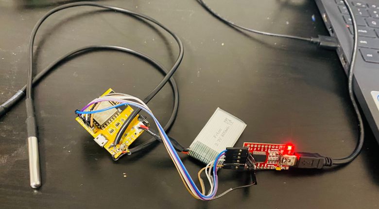
From the board manager, Select Generic ESP8266 Board and the COM port. Then hit the upload button to upload the code.
Testing IoT-enabled Smart Fridge with ESP8266 WebServer
After uploading the above code to the ESP8266 Board, the ESP8266 will connect to the WiFi Network and start a Webserver. To observe the IP Address, open the Serial Monitor.
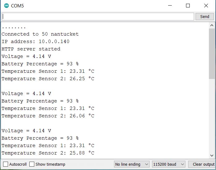
The Serial Monitor will also display the value of Battery Voltage, Battery Percentage, Fridge Temperature as well as Freezer Temperature.
Copy the IP Address from Serial Monitor and paste it on any Web Browser connected to the same Network. Once you hit enter, a beautiful webpage will be display.
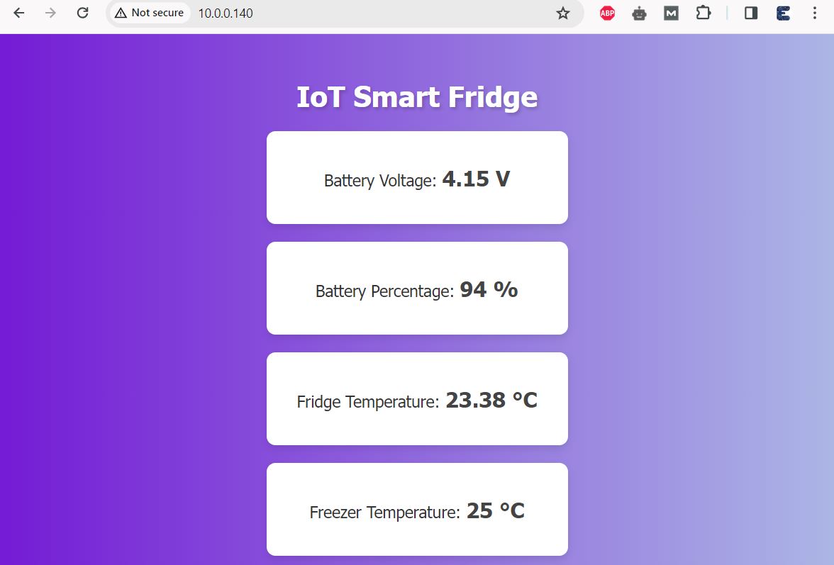
The webpage uses a gradient background and a Montserrat font, giving it a modern look. The webpage shows four main pieces of data: Battery Voltage, Battery Percentage, Fridge Temperature, and Freezer Temperature. Each piece of data is displayed in its own card-like element. The webpage uses JavaScript to fetch the latest sensor data from the /data endpoint of the server every 2 seconds.
Since the project is designed to monitor the Refrigerator temperature. So we need to place it inside the fridge and freezer.
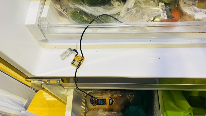
Place one of the Sensor in the fridge and the other sensor inside the freezer. Do not put your device and battery inside freezer as battery behaves abnormally under minus temperature.
Now check at the temperatures on the Webpage.
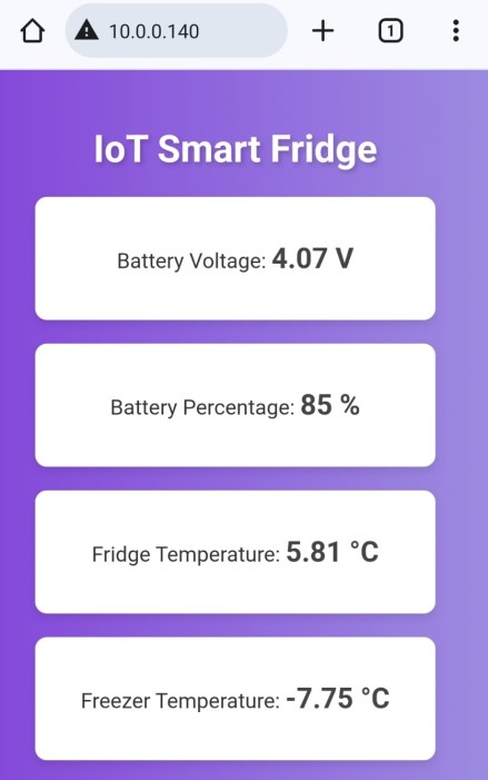
Now you will observe the massive change in temperature of the freezer. It will show the temperature in minus as shown in the image.
This is how you can monitor the real time battery voltage and temperature of your device. The the IoT-enabled Smart Fridge with ESP8266 WebServer can be a asset to you in case you wanna know about your fridge conditions in real time.
Video Tutorial & Guide


2 Comments
Can you please provide the Sch file as it is available in image. I want to modify the project and make one for my self. Also can this same be used for esp32 ? Can you make a POWER effficient and deep sleep based core project for esp32 and nodemcu both ? So that it can be used as a template to other electronics project. I am subscriber and follower of your channel.
Hi kindly reply