

Overview
This is a simple Home Automation Project using Amazon AWS IoT Core & ESP32 WiFi Module. Earlier we learned about Getting Started with AWS IoT Core with ESP32 and also ESP8266. We also made an AWS IoT Lamp using the ESP32 & controlled the lamp through the AWS Dashboard.
The AWS IoT Core is a managed cloud service that lets connected devices easily and securely interact with cloud applications and other devices. The AWS IoT Core MQTT messaging service lets you send and receive MQTT messages to and from AWS IoT Core. Using the Publish/Subscribe feature we can basically receive or send any data to & the AWS IoT Core dashboard.
This tutorial is all about Controlling Peripherals like AC Appliances like bulbs via Relay from AWS IoT Dashboard using ESP32 WiFi Module. We would basically call it a Home Automation Project. Home automation is the automatic control of electronic devices in your home. These devices are connected to the Internet, which allows them to be controlled remotely. Earlier we made so many Home Automation projects which are as follows:
- Home Automation with Arduino IoT Cloud & ESP32
- Home Automation using Google Firebase & ESP8266
- Home Automation using Blynk & ESP8266
- Home Automation using ESP8266 WebServer
- Home Automation using Android & ESP8266
- Home Automation using ESP8266 & Alexa
- Home Automation using ESP32 & Alexa
- Home Automation using ESP32 WebServer
Bill of Materials
For this project, we will need the following components. The component list, footprint, and quantity are given below.
| S.N. | Component | Designator | Footprint | Quantity |
|---|---|---|---|---|
| 1 | Capacitor 100nf | C1, C3, C6, C7, C8, C9, C10, C11 | CAP_0805 | 8 |
| 2 | Capacitor 10uf | C2, C4, C5 | CAP_0805 | 3 |
| 3 | Capacitor 220uF, 25V | C12 | FP-RAD-TH-D_10_0_5-L_16_1-MFG | 1 |
| 4 | Diode 1N4007 | D1, D2, D3, D4 | DIOM5027X262N | 4 |
| 5 | SP4322-01ETG | D5 | SP432201ETG | 1 |
| 6 | Optocoupler PC817C | IC1, IC3, IC4, IC5 | DIP762W60P254L458H450Q4N | 4 |
| 7 | ESP32 WROOM-32 | IC2 | ESP32WROOM3216MB | 1 |
| 8 | 2-Pin Terminal Block | J1 | 1 | |
| 9 | 3-Pin Terminal Block | J2, J3, J4, J5 | 4 | |
| 10 | Relay SRD-05VDC-SL-C | K1, K2, K3, K4 | SRD | 4 |
| 11 | LED Red | LED1, LED2, LED3, LED4, LED5 | LEDC2012X80N | 5 |
| 12 | Male Header 6 Pin | P1 | HDR1X6 | 1 |
| 13 | HLK-10M05 | PS1 | HLK10M05 | 1 |
| 14 | Transistor BC847B | Q1, Q2, Q3, Q4, Q5, Q6 | BC847B215 | 6 |
| 15 | Resistor 220R | R1, R3, R9, R11, R14, R16, R17, R19 | 805 | 8 |
| 16 | DNP | R2, R10, R15, R18 | 805 | 4 |
| 17 | Resistor 12K | R4, R12, R13 | 805 | 3 |
| 18 | Resistor 1K | R5, R7, R8, R24 | 805 | 4 |
| 19 | Resistor 470R | R6 | 805 | 1 |
| 20 | Resistor 10K | R20, R21, R22, R23 | 805 | 4 |
| 21 | Push Button Switch | S1, S2, S3, S4 | B3W1020 | 4 |
| 22 | Manual Switch (Optional) | SW1, SW2, SW3, SW4 | HDR1X2 | 4 |
| 23 | HT7333 3.3V Voltage Regulator | U1 | IC_HT7333 | 1 |
Circuit Diagram & Hardware Design
Let us take a look at the Schematic of AWS IoT Core Based Home Automation Project with ESP32. The schematic is drawn using the Altium Designer Software.

We used SMD resistors, capacitors, and LED with the 0805 package. To convert 220V AC to 5V DC, we used an AC-to-DC Converter from Hi-Link. For providing power to ESP32 raw chip and other peripherals, a low-power LDO HT7333 IC was used. To separate the high-power line from the 3.3V circuit PC817 optocoupler IC is used. The LED5 in the circuit is used to indicate power.

Similarly the LED1, LED2, LED3 & LED4 is used to represent Relay1, Relay2, Relay3 & Relay4 output respectively. The LED5 is a power indication LED. The 4 Relays are connected to ESP32 via GPIO Pins 12, 14, 27, 26. The push buttons SW1, SW2, SW3, and SW4 are used in the manual controlling of Relays. They are connected to GPIO Pins 5, 17, 13, 16. You may attach a manual switch there and program the controller to control the circuit.
You can connect 4 home appliannces using the Relay connections at 3 Pin Terminal J2, J3. J4, J5. The 2 Pin Terminal J1 is used to supply AC Power directly to the Circuit. A Capacitor C12 of 220uF, 25V is connected to PCB stop voltage fluctuations.

To program the ESP32 raw chip, the FTDI pin is provided. We can connect an FTDI Module (USB-to-TTL Converter) to program the ESP32 Chip directly.
Project PCB Gerber File & PCB Ordering Online
We have designed the PCB using the Altium Designer Software. It took quite a lot of time fixing all the isses in the PCB but still we managed to design a complete working custom PCB. The PCB design looks like this.

Here is the 3D View of the PCB from the front side as well as from the backside.

The Gerber File for the PCB is given below. You can simply download the Gerber File and order the PCB from PCBGOGO at 1$ only.
You can use this Gerber file to order high-quality PCB for this project. To do that visit the PCBGOGO official website by clicking here: https://www.pcbgogo.com/.

You can now upload the Gerber File by choosing the Quote Now option. From these options, you can choose the Material Type, Dimensions, Quantity, Thickness, Solder Mask Color and other required parameters.

After filling all details, select your country and shipping method. Finally you can place the order.
PCB & Hardware Assembly
After ordering the PCB, it took almost 5 days and I got my PCB.

The PCB quality from PCBGOGO is superb with very high quality. That is why most people trust PCBGOGO for PCB/PCBA Services.


First solder all the SMD components like resistors, capacitors, transistors, LEDs, voltage regulators & diodes. Be careful about the SMD LED polarity, place it in the proper direction. The SMD soldering is to be done on the both sides.

After soldering all these, you can solder the ESP32 raw chip. The final stage would be soldering all the through-hole components like Optocoupler IC, terminal block, Relays, male-female headers, and AC-to-DC Converter Module.

After soldering all the components, the ESP32 Home Automation Board is ready for the test. You can upload a blink sketch by connecting a USB-to-TTL Converter Module.

Note: There were some voltage fluctuation issues in the designed PCB, so I have updated the design by adding 220uF capacitor. Also, some connection issues have been fixed. The Gerber file above is updated and the PCB would be little different from shown above. But overall the functionality is same.
Setting up Amazon AWS IoT Core Dashboard
The signing up part for the Amazon Web Services is already explained in the previous post. You can follow the AWS IoT Core Getting Started tutorial.
After successfully signing in, the AWS Management Console window will open. In the services search tab at the top right ‘IoT core’ & hit enter.

You can click on IoT Core, so an AWS IoT Dashboard will appear now.

On the left side of the dashboard, there are so many options. But we need to work with two options here. One is the manage option and the other one is the secure option.
Creating a Thing
Now we need to create a thing associated with our project. For this, follow the following steps:
- Specifying thing properties
- Configuring device certificate
- Attaching policies to certificate
Under the manage option click on Thing. Now we need to create a Thing here. So, click on Create Things here.

You can select whether create a single thing or create many things. But for our applications, select create a single thing. Then click on Next.

Specify Thing Properties
Here we need to specify the Thing properties. First, give a thing name. You can name it anything. For example, I will name it Home_Automation.

Under additional configurations, there is no need to make any changes.
Under the device shadow option, select the first option as No shadow. Then click on Next.
Generate Device Certificate
Now you need to configure device certificate. So here you can auto-generate a new certificate or use your own certificate or upload CSR or skip this.

But the AWS recommendation is to select the Auto Generate New Certificate. Then click on Next.
Create & Attach Policy
Now we need to attach a policy to the Things we created. But no policies are here right now. So we need to create a policy first.

So click on create policy. Here give any name to the policy. For example, I will give it a name as “Automation_Policy“.

Now the add statement part is very important. Under the action, type IoT. So multiple options will pop up. From here we will only need to Subscribe, Connect and Receive.

Now click on create to create the policy. So the policy has been created successfully.
Now go back to Create Thing option. So a policy option will appear. We need to attach the policies to the certificate. So select the appeared policy and click on create a thing.

Downloading Certificates and Keys
Now we need to download the required certificates from this list.

First, download the device certificate and then rename it as a device certificate for identification.
Also, download the public key and rename it as a public key. Then download the private key and rename it as a private key.
In the Root CA Certificates, there are two certificates here. But we just need a Root CA1 certificate, so download it as well.

So we have downloaded all the certificates that we need for our project.
Source Code/Program
The Source Code/Program for Home automation using Amazon AWS IoT Core & ESP32 is written in Arduino IDE. Before moving to the code part, we need to install few libraries to the Arduino IDE. Download the PubSubClient Library and add it to the Arduino IDE library folder.
Here is the complete code for the project that requires a lot of modifications. Copy it and paste it to your Arduino IDE.
|
1 2 3 4 5 6 7 8 9 10 11 12 13 14 15 16 17 18 19 20 21 22 23 24 25 26 27 28 29 30 31 32 33 34 35 36 37 38 39 40 41 42 43 44 45 46 47 48 49 50 51 52 53 54 55 56 57 58 59 60 61 62 63 64 65 66 67 68 69 70 71 72 73 74 75 76 77 78 79 80 81 82 83 84 85 86 87 88 89 90 91 92 93 94 95 96 97 98 99 100 101 102 103 104 105 106 107 108 109 110 111 112 113 114 115 116 117 118 119 120 121 122 123 124 125 126 127 128 129 130 131 132 133 134 135 136 137 138 139 140 141 142 143 144 145 146 147 148 149 150 151 152 153 154 155 156 157 158 159 160 161 162 163 164 165 166 167 168 169 170 171 172 173 |
#include <pgmspace.h> #include <WiFiClientSecure.h> #include <PubSubClient.h> #include "WiFi.h" #define AWS_IOT_SUBSCRIBE_TOPIC "esp32/sub" // MQTT topic to subscribe to for commands #define THINGNAME "***********" // Unique identifier for your device, change this const char WIFI_SSID[] = "***********"; // Your WiFi SSID const char WIFI_PASSWORD[] = "***********"; // Your WiFi password const char AWS_IOT_ENDPOINT[] = "***********"; // Your AWS IoT endpoint, change this // Amazon Root CA 1, necessary for secure communication static const char AWS_CERT_CA[] PROGMEM = R"EOF( -----BEGIN CERTIFICATE----- // Paste certificate here -----END CERTIFICATE----- )EOF"; // Device Certificate, replace with your device's certificate static const char AWS_CERT_CRT[] PROGMEM = R"KEY( -----BEGIN CERTIFICATE----- // Paste certificate here -----END CERTIFICATE----- )KEY"; // Device Private Key, replace with your device's private key static const char AWS_CERT_PRIVATE[] PROGMEM = R"KEY( -----BEGIN RSA PRIVATE KEY----- // Paste private key here -----END RSA PRIVATE KEY----- )KEY"; #define lamp1 19 // GPIO pin for lamp 1 #define lamp2 21 // GPIO pin for lamp 2 #define lamp3 22 // GPIO pin for lamp 3 #define lamp4 23 // GPIO pin for lamp 4 WiFiClientSecure net = WiFiClientSecure(); PubSubClient client(net); // Function to handle incoming MQTT messages void messageHandler(char* topic, byte* payload, unsigned int length) { Serial.print("Incoming message on topic ["); Serial.print(topic); Serial.print("]: "); // Construct message from payload String received_msg = ""; for (int i = 0; i < length; i++) { received_msg += (char)payload[i]; Serial.print((char)payload[i]); } Serial.println(); // Control the lamps based on the received message // Check for commands and actuate corresponding lamp if (received_msg == "ON1") { digitalWrite(lamp1, HIGH); // Turn on lamp 1 Serial.println("Lamp1 turned on"); } else if (received_msg == "OFF1") { digitalWrite(lamp1, LOW); // Turn off lamp 1 Serial.println("Lamp1 turned off"); } // Repeat for other lamps... else if (received_msg == "ON2") { digitalWrite(lamp2, HIGH); Serial.println("Lamp2 turned on"); } else if (received_msg == "OFF2") { digitalWrite(lamp2, LOW); Serial.println("Lamp2 turned off"); } else if (received_msg == "ON3") { digitalWrite(lamp3, HIGH); Serial.println("Lamp3 turned on"); } else if (received_msg == "OFF3") { digitalWrite(lamp3, LOW); Serial.println("Lamp3 turned off"); } else if (received_msg == "ON4") { digitalWrite(lamp4, HIGH); Serial.println("Lamp4 turned on"); } else if (received_msg == "OFF4") { digitalWrite(lamp4, LOW); Serial.println("Lamp4 turned off"); } } void setup() { Serial.begin(115200); // Start serial communication // Initialize GPIO pins for lamps as outputs and set them off pinMode(lamp1, OUTPUT); pinMode(lamp2, OUTPUT); pinMode(lamp3, OUTPUT); pinMode(lamp4, OUTPUT); digitalWrite(lamp1, LOW); digitalWrite(lamp2, LOW); digitalWrite(lamp3, LOW); digitalWrite(lamp4, LOW); WiFi.mode(WIFI_STA); // Set WiFi to station mode WiFi.begin(WIFI_SSID, WIFI_PASSWORD); // Connect to WiFi network Serial.println("Connecting to Wi-Fi"); // Wait for connection while (WiFi.status() != WL_CONNECTED) { delay(500); Serial.print("."); } // Configure WiFiClientSecure to use the AWS IoT device credentials net.setCACert(AWS_CERT_CA); net.setCertificate(AWS_CERT_CRT); net.setPrivateKey(AWS_CERT_PRIVATE); // Connect to the MQTT broker on the AWS endpoint client.setServer(AWS_IOT_ENDPOINT, 8883); // Set the function to handle messages client.setCallback(messageHandler); Serial.println("Connecting to AWS IOT"); // Attempt to connect to AWS IoT while (!client.connect(THINGNAME)) { Serial.print("."); delay(100); } // Check if connection was successful if (!client.connected()) { Serial.println("AWS IoT Timeout!"); return; } // Subscribe to the MQTT topic for receiving commands client.subscribe(AWS_IOT_SUBSCRIBE_TOPIC); Serial.println("AWS IoT Connected!"); } void loop() { // Keep the MQTT connection alive client.loop(); delay(1000); } |
Modifying Arduino Sketch according to the Thing
Now it’s time to modify the Arduino Sketch File. So lets begin the modification.
Here we need to include a thing name. You can go to the things section of AWS Console and copy the thing name. The Things name in this project is Home_Automation. Paste the thing name to the following line of code.
|
1 |
#define THINGNAME "***************" |
Under the WiFi SSID and password, enter the WiFi SSID and Password of your local network.
|
1 2 |
const char WIFI_SSID[] = "***************"; const char WIFI_PASSWORD[] = "***************"; |
Now, we need to insert the AWS IoT Endpoint here. To get the endpoint, go to the settings part of AWS Dashboard. Yow will get the endpoint.

Click on the copy icon to copy the endpoint. Go back to Arduino IDE and paste it on the following line.
|
1 |
const char AWS_IOT_ENDPOINT[] = "***************"; |
You need to insert the Amazon Root CA1 in between the following line.
|
1 2 3 4 5 6 |
// Amazon Root CA 1 static const char AWS_CERT_CA[] PROGMEM = R"EOF( -----BEGIN CERTIFICATE----- -----END CERTIFICATE----- )EOF"; |
So for this, we need to go back to the certificate that we downloaded earlier. Open this file with Notepad++ and copy all the text.

Then go back to Arduino IDE and insert the copied text between begin certificate and the end certificate.
Under the “Device Certificate” lines, we need to paste the device certificate text. So open the device certificate file that we downloaded earlier. And again copy the text and paste it between the begin certificate and end certificate section.
|
1 2 3 4 5 |
// Device Certificate static const char AWS_CERT_CRT[] PROGMEM = R"KEY( -----BEGIN CERTIFICATE----- -----END CERTIFICATE----- |
Under the “Device Private Key“, we need to insert the device’s private key. So go to the downloaded folder again and open the device’s private key file using Notepad++. Again copy the text and paste it between begin & end parts.
|
1 2 3 4 5 |
// Device Private Key static const char AWS_CERT_PRIVATE[] PROGMEM = R"KEY( -----BEGIN RSA PRIVATE KEY----- -----END RSA PRIVATE KEY----- |
So all the modification of the Arduino Sketch for ESP32 AWS IoT Core Home Automation Project is done now.
Home Automation using Amazon AWS IoT Core & ESP32
To progam the ESP32 Raw Chip, connect the FTDI Module to your FTDI Pin of the PCB.

Then go to the tools & select ESP32 Board that you are using for this project. Also, select the COM port. Then click on the upload option to upload the code to the ESP32 board.
Note: While uploading the code disconnect the AC Power line from the power source.

Now remove the FTDI Module connection and power the device using the AC Supply.

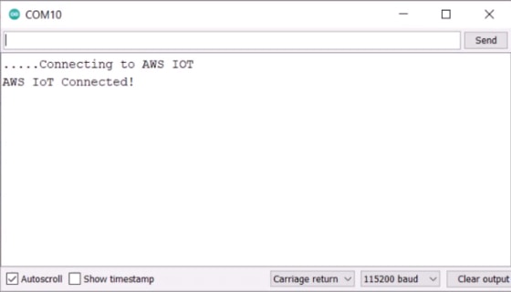
The ESP32 will try connecting to the WiFi Network. Once it gets connected to the WiFi Network, it will try connecting to the AWS IoT Server. The Serial Monitor will show this message.
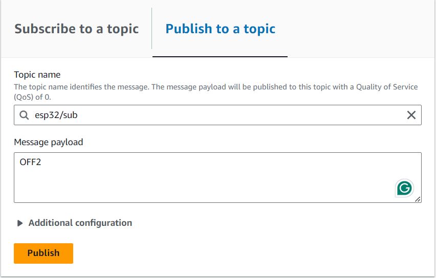
Now we need to check whether we are able to publish a topic to control all the home appliances.
To do that, you need to publish a topic. For that type “esp32/sub“ under the topic filter section. Under Message Payload type the following command a command to turn ON/OFF the Relay respectively.
Type ON1, ON2, ON3, ON4 to turn ON Relay1, Relay2, Relay3, Relay4. Similarly type OFF1, OFF2, OFF3, OFF4 to turn OFF Relay1, Relay2, Relay3, Relay4 repectively.
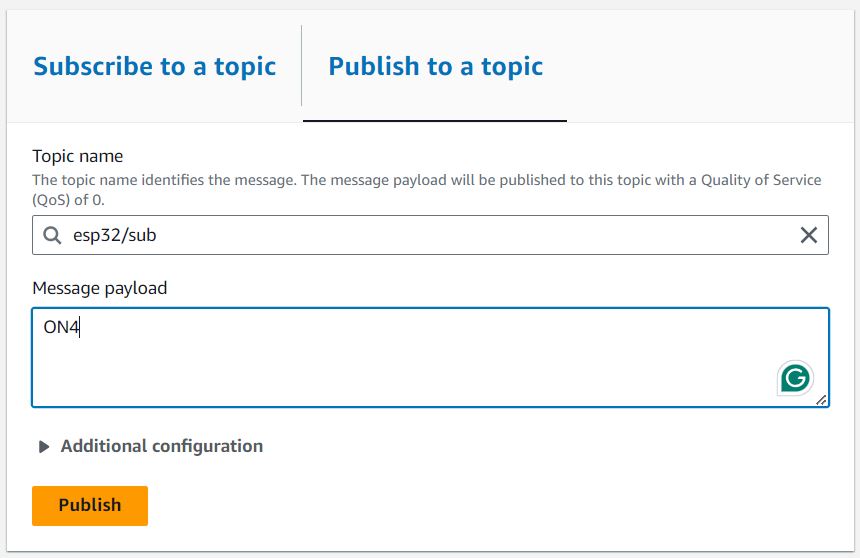
Under additional configuration do nothing. Then click on publish. Immediately you can see the message sent to the Serial Monitor.
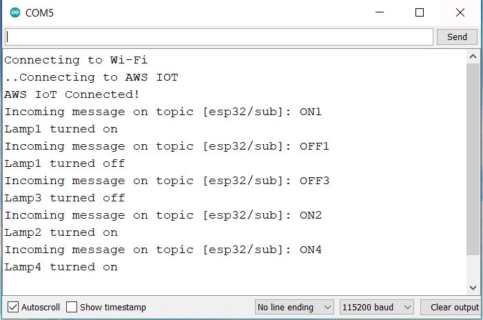
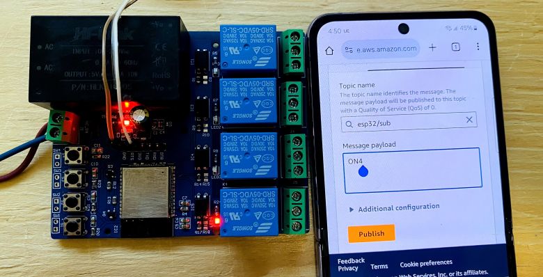
At this moment the Relay4 will turn ON immediately. And any appliances connected to the Relay4 will turn ON.
Now to turn OFF the Relay2, send OFF2 from the publish window of AWS Dashboard. The Relay4 should turn OFF immediately.
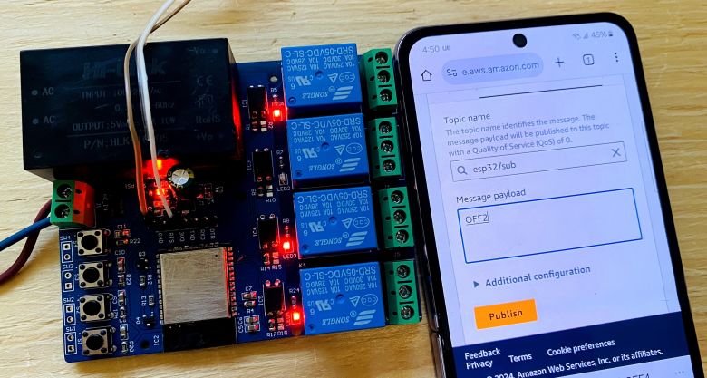
You can send other commands as well for testing the ON/OFF functionality.
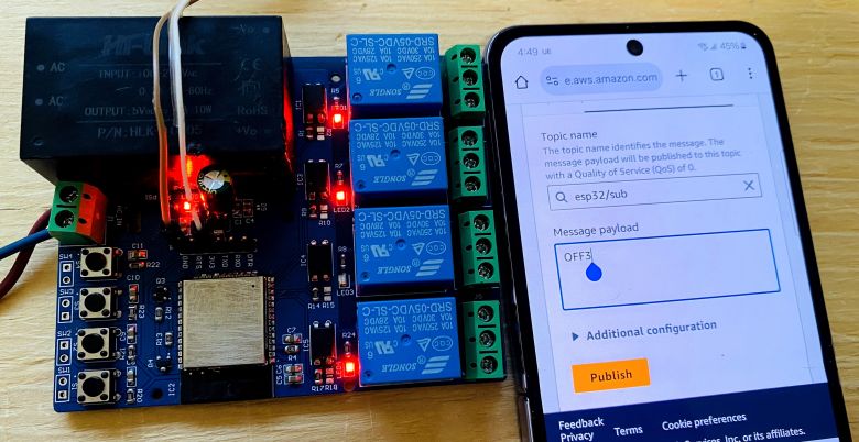
This is how you can control any home appliances with Amazon AWS IoT Core using ESP32 WiFi Module & make your own Home Automation project. The demo is done with 4 different Relays. You can control any appliances through those Relays.
 & Live Dashboard")


