

Overview: Home Automation with Arduino IoT Cloud & ESP32
In this project, we will learn about the application of Arduino IoT Cloud with ESP32. Recently the Arduino Community launched their IoT platform called Arduino IoT Cloud. You can connect multiple devices to each other and allow them to exchange real-time data. You can also monitor data from anywhere using a simple user interface. To learn more about the Arduino IoT Cloud, you can go through the documentation part.
As an example, you can control multiple home appliances from the Arduino IoT Cloud Dashboard. We will interface a 4 channel relay with ESP32 WiFI Module & send the ON/OFF commands either from the mobile phone dashboard or from Computer Dashboard and Control Relay, Light, or anything else. So, let’s see how can deploy this entire system. To know more about the Arduino IoT Cloud, you can refer the article Getting Started Tutorial
But before that, you can check some of our Home Automation Projects made using ESP8266 or ESP32:
1. Home Automation using NodeMCU & Alexa
2. Home Automation using NodeMCU & Android
3. Home Automation using ESP8266 WebServer
4. Home Automation using Blynk & NodeMCU
5. Home Automation using Google Firebase & NodeMCU
6. Home Automation using AWS IoT Core & ESP32
7. Home Automation using Alexa & ESP32
8. Home Automation using ESP32 WebServer
Bill of Materials
For this project, we will need an ESP32 Board, 4 channel relay, few jumper wires and breadboard. For demo, we can use 4 bulbs with 4 holders or any other electrical appliances.
All the components can be easily purchased from Amazon through the below Amazon purchase links.
| S.N. | Components Name | Quantity | Purchase Links |
|---|---|---|---|
| 1 | ESP32 WiFi Module | 1 | Amazon | AliExpress |
| 2 | Relay 5V | 4 | Amazon | AliExpress |
| 3 | 7805 Voltage Regulator | 1 | Amazon | AliExpress |
| 4 | DC Power Jack DCJ0202 | 1 | Amazon | AliExpress |
| 5 | Diode 1N4007 | 4 | Amazon | AliExpress |
| 6 | Resistor 330-ohm | 5 | Amazon | AliExpress |
| 7 | BC547 NPN Transistor | 4 | Amazon | AliExpress |
| 8 | Terminal Block 5mm | 4 | Amazon | AliExpress |
| 9 | LED 5mm Any Color | 1 | Amazon | AliExpress |
| 10 | Female Header 2.54mm | 2 Set | Amazon | AliExpress |
Circuit Diagram & Hardware
The circuit for Home Automation using Arduino IoT Cloud & ESP32 is very simple. I used Fritzing software to draw the schematic. The below diagram is only for the breadboard Assembly.

The ESP32 Board has so many GPIOs Pins. In this project, we will be using GPIO19, GPIO21, GPIO22 & GPIO23 for controlling the Relay. Across the output of the relay, we will use bulbs for testing and demo. You can use a 9V DC Adapter to power the circuit as the output of 7805 Voltage Regulator IC connects to Vin of ESP32.

Project PCB Gerber File & PCB Ordering Online
If you don’t want to assemble the circuit on a breadboard and you want PCB for the project, then here is the PCB for you. I used EasyEDA to design the PCB. The PCB Board for Home Automation with ESP32 looks something like below.

The Gerber File for the PCB is given below. You can simply download the Gerber File and order the PCB from ALLPCB at 1$ only.
You can use this Gerber file to order high quality PCB for this project. To do that visit the ALLPCB official website by clicking here: https://www.allpcb.com/.

You can now upload the Gerber File by choosing the Quote Now option. From these options, you can choose the Material Type, Dimensions, Quantity, Thickness, Solder Mask Color and other required parameters.

After filling all details, select your country and shipping method. Finally you can place the order.
You can assemble the components on the PCB Board.

Setting Up Arduino IoT Cloud Dashboard

Now it’s time to set up the Arduino IoT Cloud Dashboard. Go to the Arduino Store. Click on IoT Cloud.
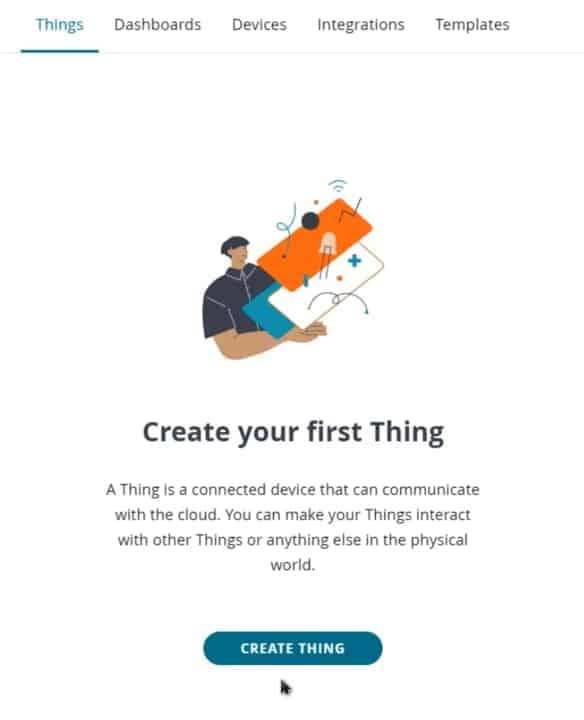
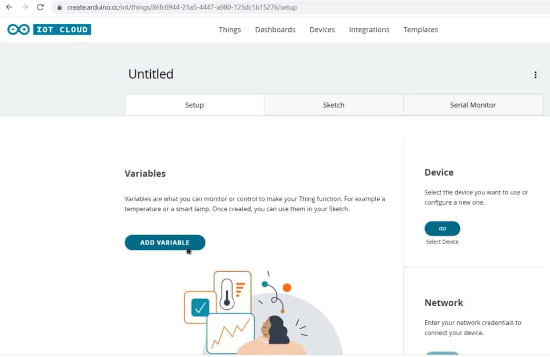
Then you need to create a Thing first. To do that click on add variable.

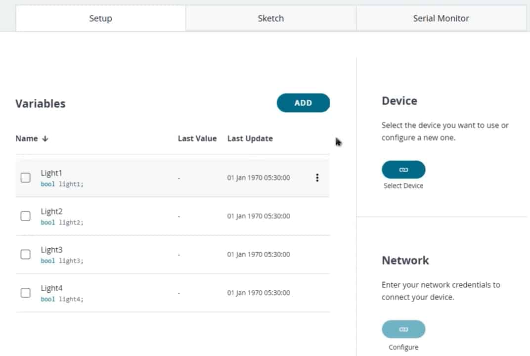
Name the variable anything like Light1. In the variable type select bool. So an automatic variable declaration will be done. Then click on Add variable. The first variable is created.
Similarly create other three variables with names Light2, Light3, Light4.
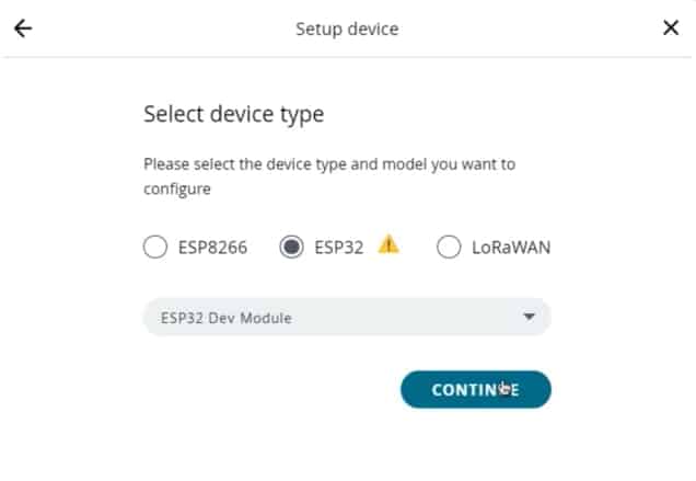
Now, we need to configure a device as well. For that select the device option. From the list select a 3rd party device. Then select ESP32. From this list select ESP32 Developer Module.
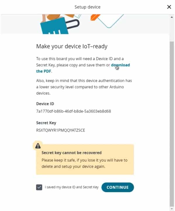
Click to continue and give any name to the device. Then click Next. So device ID & Secret Key is created here. Save this device ID for the coding part. Or simply download this PDF File which has the information of Secret Key. Then click on continue.
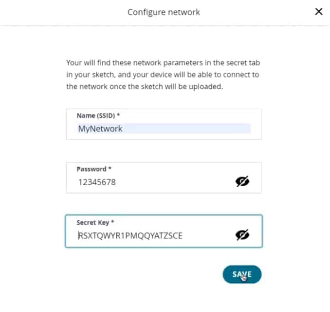
Now again you need to set up the Network Credentials. So input your SSID, Password as well as Secret Key that you created earlier. Finally, everything is set now.
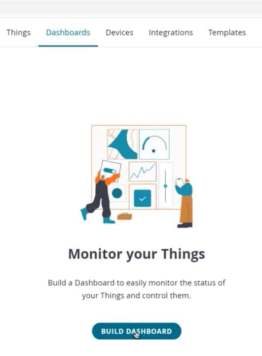
Go to the dashboard. Here we need to build a dashboard.
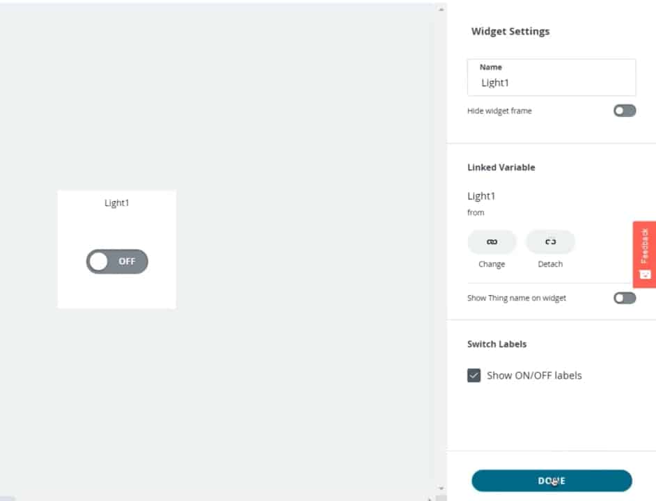
From the edit option add a variable. So select switch.
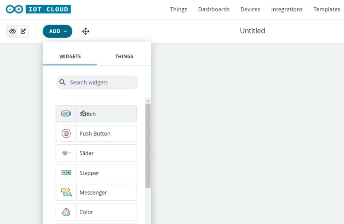
Give it any name. Then link a variable. Click on Done.
Similarly, add 3 more variables for 3 different switches and link the variable to them. You can arrange the widget or resize the widget as you wish.
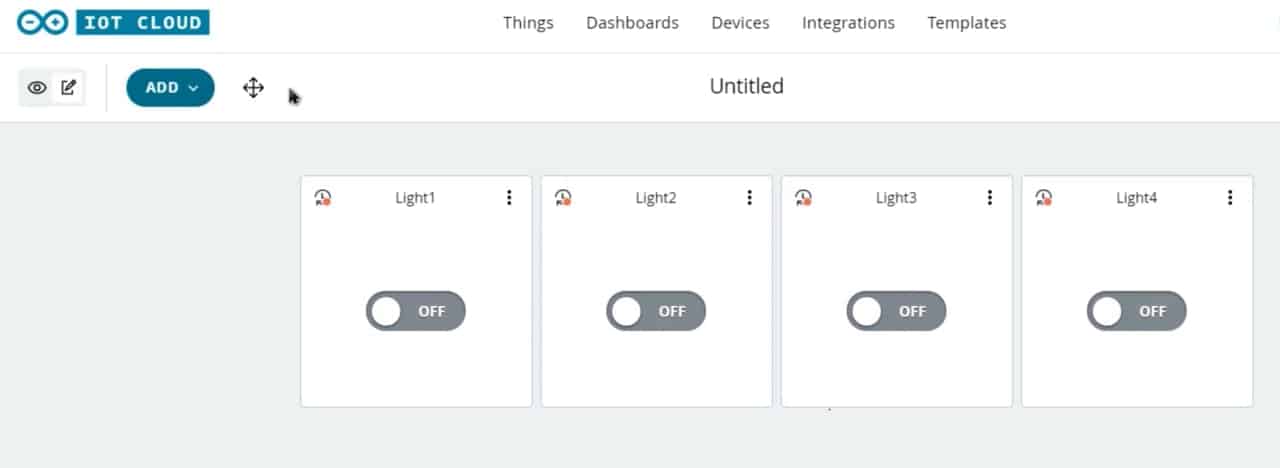
So finally you are done. The dashboard setup is ready.
Source Code/Program
Now let’s go to the sketch for Home Automation with Arduino IoT Cloud & ESP32.

There are 4 variables with bool automatically declared.
|
1 2 3 4 |
bool light1; bool light2; bool light3; bool light4; |
In the setup part, we will define 4 pins of ESP32 as output. Those 4 pins are pins 19, 21, 22, and 23.
|
1 2 3 4 |
pinMode (19, OUTPUT); pinMode (21, OUTPUT); pinMode (22, OUTPUT); pinMode (23, OUTPUT); |
Initialize them with high logic, so that all appliances are turned off initially.
|
1 2 3 4 |
digitalWrite (19, HIGH); digitalWrite (21, HIGH); digitalWrite (22, HIGH); digitalWrite (23, HIGH); |
Below the void Light function, assign a condition that if the command from the Arduino IoT Cloud Dashboard Pin is high, the relay should turn ON. Else if the command is low, the relay should turn OFF.
|
1 2 3 4 5 6 7 8 |
if (light1==1) { digitalWrite (19, LOW); } else { digitalWrite (19, HIGH); } |
Here is the complete code that you can use for this project.
Home_Automation.ino
|
1 2 3 4 5 6 7 8 9 10 11 12 13 14 15 16 17 18 19 20 21 22 23 24 25 26 27 28 29 30 31 32 33 34 35 36 37 38 39 40 41 42 43 44 45 46 47 48 49 50 51 52 53 54 55 56 57 58 59 60 61 62 63 64 65 66 67 68 69 70 71 72 73 74 75 76 77 78 79 80 81 82 83 84 85 86 87 88 89 90 91 92 93 94 95 96 97 98 99 100 101 102 103 104 105 106 107 |
#include "arduino_secrets.h" /* Sketch generated by the Arduino IoT Cloud https://cloud.arduino.cc/ Arduino IoT Cloud Variables description The following variables are automatically generated and updated when changes are made to the Thing bool light1; bool light2; bool light3; bool light4; Variables which are marked as READ/WRITE in the Cloud Thing will also have functions which are called when their values are changed from the Dashboard. These functions are generated with the Thing and added at the end of this sketch. */ #include "thingProperties.h" void setup() { // Initialize serial and wait for port to open: Serial.begin(9600); pinMode (19, OUTPUT); pinMode (21, OUTPUT); pinMode (22, OUTPUT); pinMode (23, OUTPUT); digitalWrite (19, HIGH); digitalWrite (21, HIGH); digitalWrite (22, HIGH); digitalWrite (23, HIGH); // This delay gives the chance to wait for a Serial Monitor without blocking if none is found delay(1500); // Defined in thingProperties.h initProperties(); // Connect to Arduino IoT Cloud ArduinoCloud.begin(ArduinoIoTPreferredConnection); /* The following function allows you to obtain more information related to the state of network and IoT Cloud connection and errors the higher number the more granular information you’ll get. The default is 0 (only errors). Maximum is 4 */ setDebugMessageLevel(2); ArduinoCloud.printDebugInfo(); } void loop() { ArduinoCloud.update(); // Your code here } void onLight1Change() { if (light1==1) { digitalWrite (19, LOW); } else { digitalWrite (19, HIGH); } } void onLight2Change() { if (light2==1) { digitalWrite (21, LOW); } else { digitalWrite (21, HIGH); } } void onLight3Change() { if (light3==1) { digitalWrite (22, LOW); } else { digitalWrite (22, HIGH); } } void onLight4Change() { if (light4==1) { digitalWrite (23, LOW); } else { digitalWrite (23, HIGH); } } |
thingProperties.h
|
1 2 3 4 5 6 7 8 9 10 11 12 13 14 15 16 17 18 19 20 21 22 23 24 25 26 27 28 29 30 31 32 33 34 35 36 |
// Code generated by Arduino IoT Cloud, DO NOT EDIT. #include <ArduinoIoTCloud.h> #include <Arduino_ConnectionHandler.h> const char THING_ID[] = "86fc6944-21a5-4447-a980-125dc1b15276"; const char DEVICE_LOGIN_NAME[] = "7a1770df-b86b-46df-b8de-5a3603eb8d68"; const char SSID[] = SECRET_SSID; // Network SSID (name) const char PASS[] = SECRET_PASS; // Network password (use for WPA, or use as key for WEP) const char DEVICE_KEY[] = SECRET_DEVICE_KEY; // Secret device password void onLight1Change(); void onLight2Change(); void onLight3Change(); void onLight4Change(); bool light1; bool light2; bool light3; bool light4; void initProperties(){ ArduinoCloud.setBoardId(DEVICE_LOGIN_NAME); ArduinoCloud.setSecretDeviceKey(DEVICE_KEY); ArduinoCloud.setThingId(THING_ID); ArduinoCloud.addProperty(light1, READWRITE, ON_CHANGE, onLight1Change); ArduinoCloud.addProperty(light2, READWRITE, ON_CHANGE, onLight2Change); ArduinoCloud.addProperty(light3, READWRITE, ON_CHANGE, onLight3Change); ArduinoCloud.addProperty(light4, READWRITE, ON_CHANGE, onLight4Change); } WiFiConnectionHandler ArduinoIoTPreferredConnection(SSID, PASS); |
arduino_secrets.h
|
1 2 3 |
#define SECRET_SSID "" #define SECRET_PASS "" #define SECRET_DEVICE_KEY "" |
Apart from the code part, we need to upload the code. But before that, we need to install a driver or install an Agent to flash the code directly from the browser. Follow the instruction on your screen to install the agent.
Once the driver is installed, the COM port will appear. Then select the ESP32 Developer Board from the list and the COM port as well. Then, upload the code. It will take some time to upload the code and when it’s done, some message will appear below the window.
Testing: Home Automation with Arduino IoT Cloud & ESP32
After uploading the code, open the Serial Monitor. It will show WiFi connection is established and then the device is connected to Arduino IoT Cloud Dashboard.

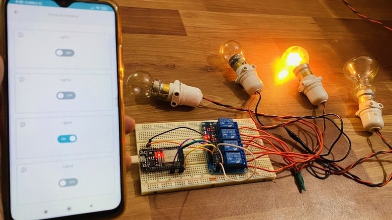
Open the dashboard now, so you can see the switch can be turned ON and OFF or enabled or disabled. You can do the initial testing. Here we can send the command to see whether the on-board LED from the Relay will turn ON or not.

You can control the light bulb from Mobile Dashboard. For that install Arduino IoT Remote from Playstore. Sign in using the same ID and password.
Go to the dashboard to control the appliances easily.
Video Tutorial & Guide


1 Comment
i am unabl to upload it in esp32 an error is comming up as “exit ststus2″ and this is the out put”/usr/local/bin/arduino-cli compile –fqbn esp32:esp32:esp32doit-devkit1 –libraries /home/builder/opt/libraries/latest –build-cache-path /tmp –output-dir /tmp/916356812/build –build-path /tmp/arduino-build-2E65C2370C665C07D5691E44416140D8 /tmp/916356812/home_dec06a
Sketch uses 891641 bytes (68%) of program storage space. Maximum is 1310720 bytes.
Global variables use 40524 bytes (12%) of dynamic memory, leaving 287156 bytes for local variables. Maximum is 327680 bytes.
Upload started
Programming with: Serial
Flashing with command:C:/Users/at350/.arduino-create/esp32/esptool_py/4.2.1/esptool.exe –chip esp32 –port COM5 –baud 921600 –before default_reset –after hard_reset write_flash -z –flash_mode dio –flash_freq 80m –flash_size 4MB 0x1000 C:/Users/at350/AppData/Local/Temp/extrafiles586069348/home_dec06a.bootloader.bin 0x8000 C:/Users/at350/AppData/Local/Temp/extrafiles586069348/home_dec06a.partitions.bin 0xe000 C:/Users/at350/AppData/Local/Temp/extrafiles586069348/tools/partitions/boot_app0.bin 0x10000 C:/Users/at350/AppData/Local/Temp/arduino-create-agent090310105/home_dec06a.bin
esptool.py v4.2.1
Serial port COM5
Connecting……
Chip is ESP32-D0WD (revision 1)
Features: WiFi, BT, Dual Core, 240MHz, VRef calibration in efuse, Coding Scheme None
Crystal is 40MHz
MAC: 8c:4b:14:5b:51:d4
Uploading stub…
Running stub…
Stub running…
Changing baud rate to 921600
Changed.
WARNING: Failed to communicate with the flash chip, read/write operations will fail. Try checking the chip connections or removing any other hardware connected to IOs.
Configuring flash size…
Flash will be erased from 0x00001000 to 0x00005fff…
Flash will be erased from 0x00008000 to 0x00008fff…
Flash will be erased from 0x0000e000 to 0x0000ffff…
Flash will be erased from 0x00010000 to 0x000ebfff…
Flash params set to 0x022f
Compressed 17440 bytes to 12090…
A fatal error occurred: Packet content transfer stopped (received 8 bytes)”