

Overview: Arduino IoT Cloud with ESP8266
Basically, this is the getting started about Arduino IoT Cloud where we will learn about using the Arduino IoT Cloud with ESP8266.
Recently the Arduino Community launched their IoT platform called Arduino IoT Cloud. The Arduino IoT Cloud provides an end-to-end solution that makes building connected projects easy for makers, IoT enthusiasts, and professionals from start to finish. The platform enables different methods of interaction, including HTTP REST API, MQTT, command-line tools, Javascript, and WebSockets. You can connect multiple devices to each other and allow them to exchange real-time data. You can also monitor data from anywhere using a simple user interface. To learn more about the Arduino IoT Cloud, you can go through the documentation part.

In this getting started tutorial, we will control an LED from the Arduino IoT Cloud Dashboard. Similarly, we will send the sensor data to the cloud dashboard and visualize it in various beautiful widgets. You can also do the Home Automation Project using Arduino IoT Cloud.
Bill of Materials
While before getting started with Arduino IoT Cloud, we need some hardware. The first component that we need is the ESP8266 Based Board. I prefer Wemos D1 Mini Board for this purpose. You can also use NodeMCU Board. We will also need a sensor. For the demo, I am using an MPU6050 Gyroscope Accelerometer sensor that can measure tilt angle. To use the switch feature you can use a 5mm LED of any color along with a 220-ohm resistor.
You can purchase all these components from Amazon.
| S.N. | Components Name | Quantity | Purchase Links |
|---|---|---|---|
| 1 | NodeMCU ESP8266 Board | 1 | Amazon | AliExpress |
| 2 | LED 5mm Any Color | 1 | Amazon | AliExpress |
| 3 | MPU6050 Gyroscope Accelerometer Sensor | 1 | Amazon | AliExpress |
| 4 | Jumper Wires | 20 | Amazon | AliExpress |
| 5 | Breadboard | 1 | Amazon | AliExpress |
| 6 | USB Cable | 1 | Amazon | AliExpress |
Circuit & Hardware

Make a simple connection as shown in the image above. Connect the MPU6050 to the I2C Pin and LED to any digital pin like GPIO0.
Setting up Arduino IoT Cloud DashBoard
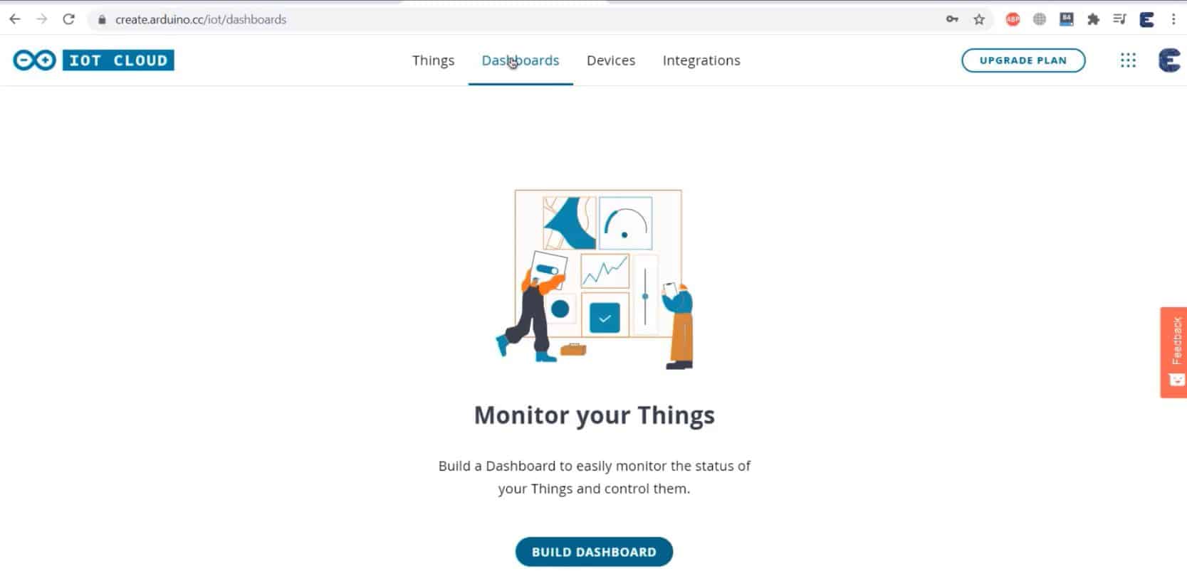
Let us set up the Arduino IoT Cloud dashboard. To do that visit the Arduino Digital Store Link.

You need to create an Arduino account or simply sign in if you created the account earlier. Click on IoT Cloud. You will be taken to the dashboard where you need to set up everything.
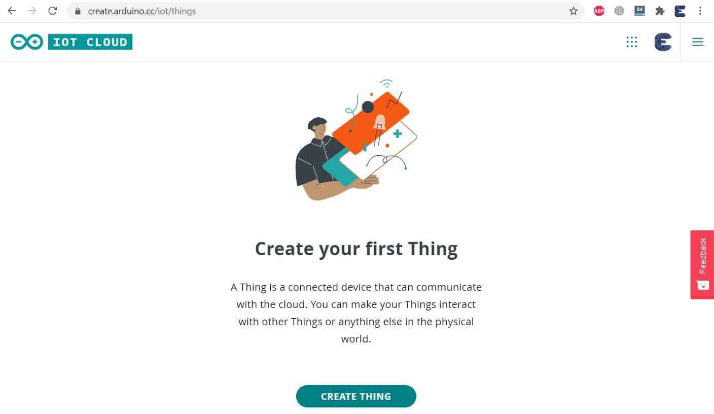
Creating Thing
Click on Create Thing now. You can see here the setup section as well as the sketch and serial monitor section.

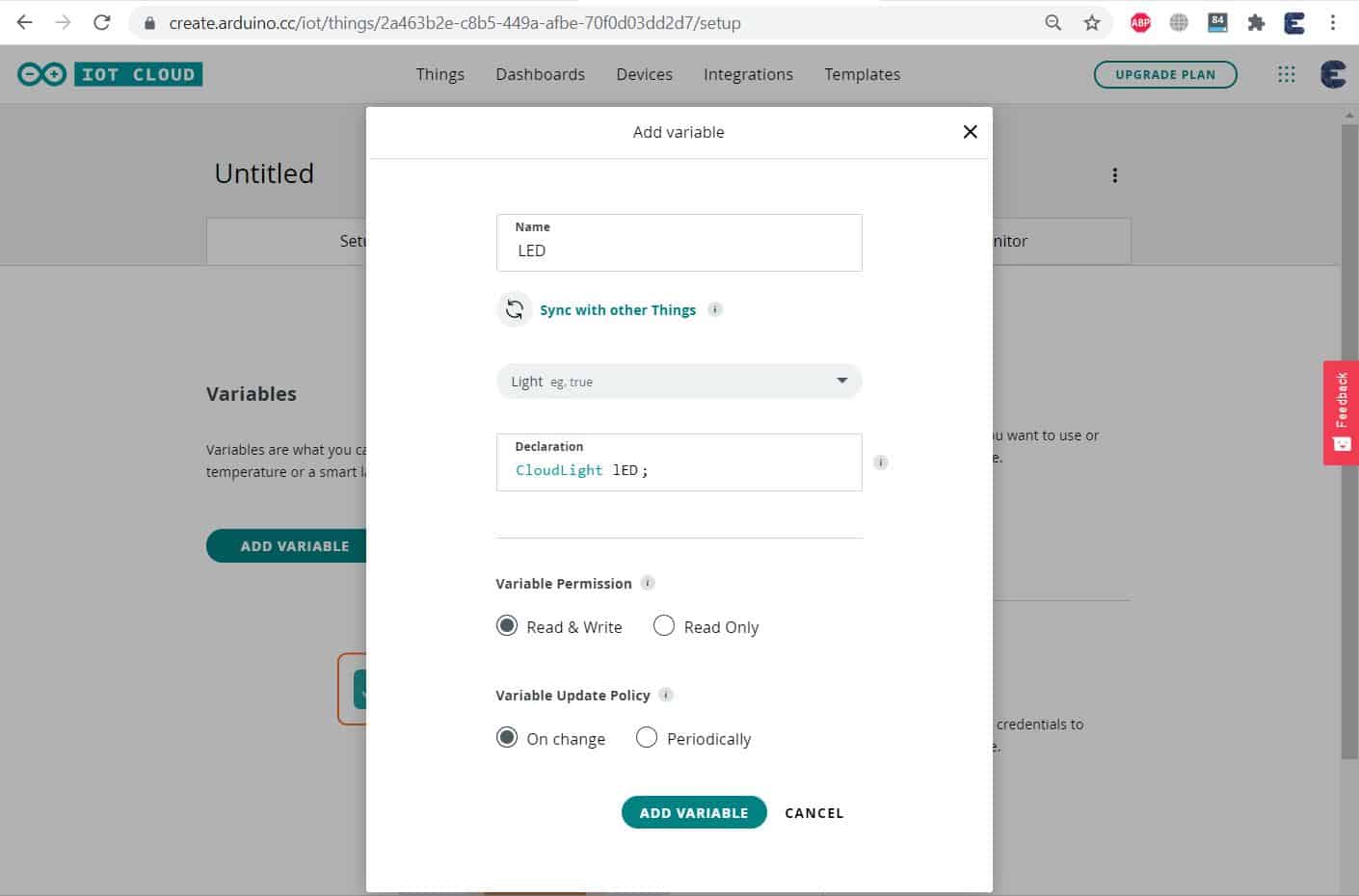
You need to add a variable now & give it any name. For example for controlling an LED, I will give it the name LED. From the variable type, select anything like Light as we need to send the 1 and 0 commands. The variable will be automatically declared as Cloud Light LED. You can assign the variable permission as either read-write or read-only. So for LED, you can assign Read & Write both. Finally, Click on Add Variable. This will create a variable successfully.
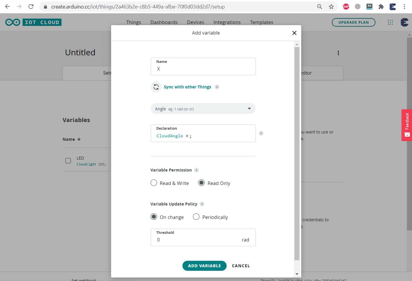
Similarly, add another variable for MPU6050 as we need to measure the tilt angle. So click on add variable and give it any name like X. From the variable list, select angle. So a variable will be automatically declared. Assign the permission as read-only since we are only reading the sensor value. Finally, click on add variable. So the 2nd variable for angle will be added.
Assign another two variables for the Y and Z angles as well.
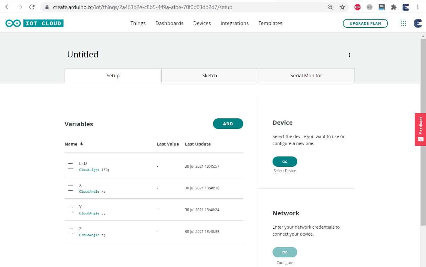
Setting Up Device
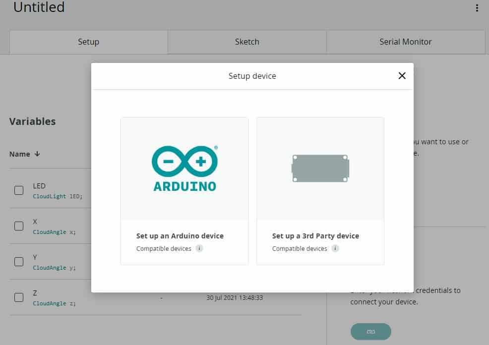
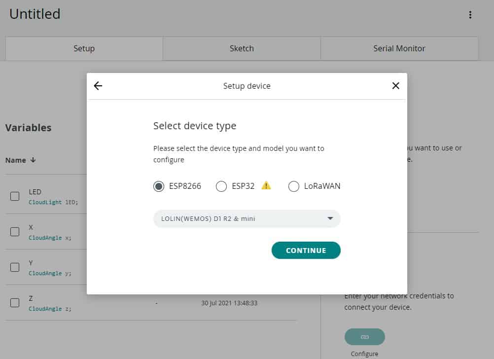
Now we need to set up the device. To do that select Device. Since ESP8266 is a 3rd party device, we will select a 3rd party device. From the list select ESP8266 Board. And from the model select your ESP8266 Type. Then, Click on Continue.
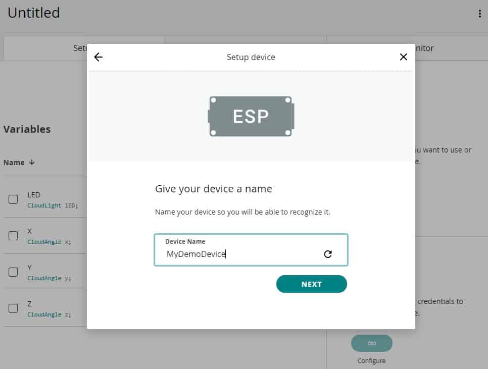
Name the device anything you would like.
A device ID and a Secret Key have been generated. These are very important while parameters in coding. You need to copy it or simply click on download the PDF.
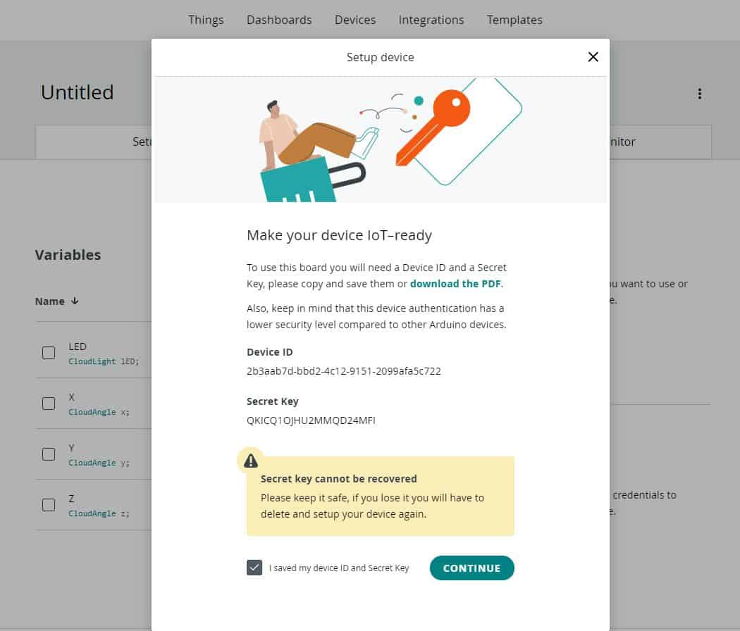
Go back to the dashboard and click on Continue. So you are finally done with the device setup.
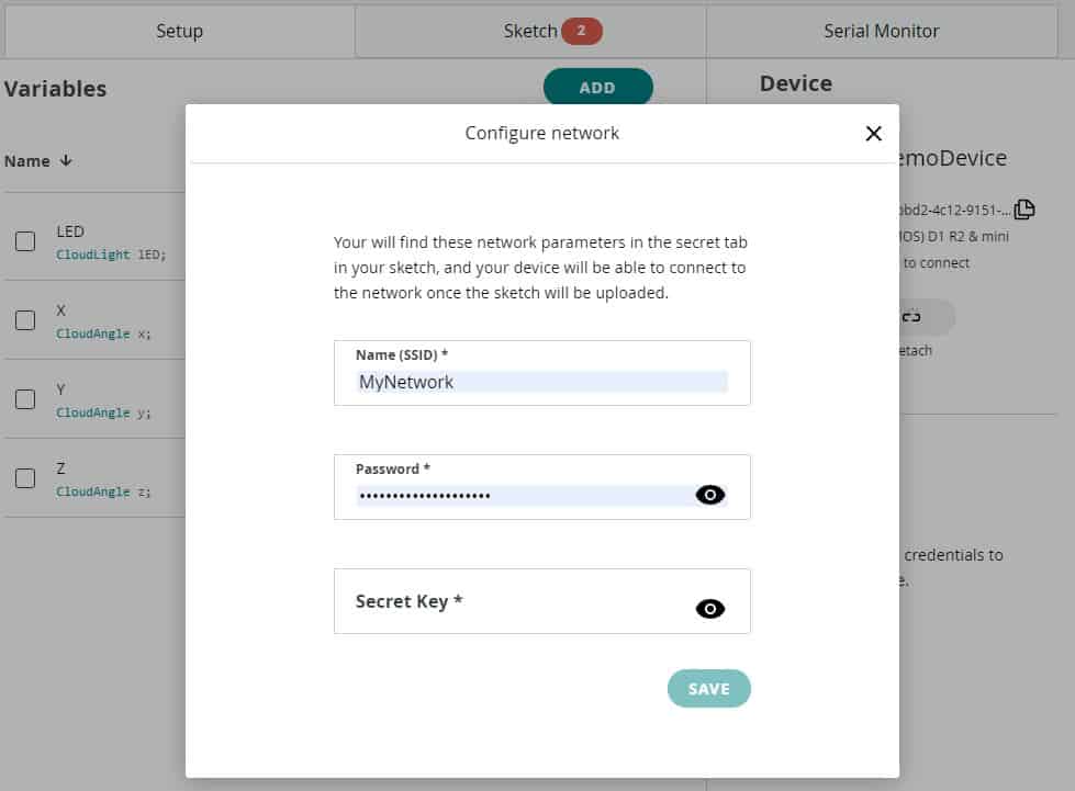
Setting Up Network
Now we also need to configure the Network. So click on Network Setup. Enter the WiFi SSID, Password & Secret Key here that you downloaded earlier. Then click on save.
Setting Up Dashboard
Go to the dashboard to set up the widgets.
Click on this edit sign. Then click on Add here. From this widget list, select switch as we want to turn ON & OFF the LED. Give any name to the switch. Then link a variable as LED from the list. Then, click on Link Variable.

Similarly, add another three widgets for X angle, Y Angle & Z Angle. You can select Gauge, Chart, or Numeric Value for each three variables. Give widget any name, then select a linked variable. From the value range, select the minimum and maximum angle range from 0 to 360.

So, our widget display dashboard is ready now.
Source Code/Program
The source code for using the Arduino IoT Cloud with ESP8266 is easy to use as some of the commands and declarations are automatically generated.

Go to the sketch tab. So a default sketch based on different variables will be created. There are some header files defined and parameters are set for LED. So we need to modify the code.
The modified code for the 3 tabs are given below.
Main_Code.ino
|
1 2 3 4 5 6 7 8 9 10 11 12 13 14 15 16 17 18 19 20 21 22 23 24 25 26 27 28 29 30 31 32 33 34 35 36 37 38 39 40 41 42 43 44 45 46 47 48 49 50 51 52 53 54 55 56 57 58 59 60 61 62 63 64 65 66 67 68 69 70 71 72 73 74 75 76 77 78 79 80 81 82 83 84 85 86 87 88 89 90 91 92 93 94 95 96 97 98 99 100 101 102 103 104 105 106 107 108 109 110 111 112 113 |
#include "arduino_secrets.h" /* Sketch generated by the Arduino IoT Cloud Thing "Untitled" https://cloud.arduino.cc/ Arduino IoT Cloud Variables description The following variables are automatically generated and updated when changes are made to the Thing CloudLight lED; CloudAngle x; CloudAngle y; CloudAngle z; Variables which are marked as READ/WRITE in the Cloud Thing will also have functions which are called when their values are changed from the Dashboard. These functions are generated with the Thing and added at the end of this sketch. */ #include "thingProperties.h" #include<Wire.h> const int MPU_addr=0x68; int16_t AcX,AcY,AcZ,Tmp,GyX,GyY,GyZ; int minVal=265; int maxVal=402; double X; double Y; double Z; void setup() { // Initialize serial and wait for port to open: Serial.begin(9600); pinMode (0, OUTPUT); Wire.begin(); Wire.beginTransmission(MPU_addr); Wire.write(0x6B); Wire.write(0); Wire.endTransmission(true); // This delay gives the chance to wait for a Serial Monitor without blocking if none is found // This delay gives the chance to wait for a Serial Monitor without blocking if none is found delay(1500); // Defined in thingProperties.h initProperties(); // Connect to Arduino IoT Cloud ArduinoCloud.begin(ArduinoIoTPreferredConnection); /* The following function allows you to obtain more information related to the state of network and IoT Cloud connection and errors the higher number the more granular information you’ll get. The default is 0 (only errors). Maximum is 4 */ setDebugMessageLevel(2); ArduinoCloud.printDebugInfo(); } void loop() { ArduinoCloud.update(); MPU6050_Read(); // Your code here } void onLEDChange() { if (lED == 1) { digitalWrite (0, HIGH); } else { digitalWrite (0, LOW); } // Do something } void MPU6050_Read() { Wire.beginTransmission(MPU_addr); Wire.write(0x3B); Wire.endTransmission(false); Wire.requestFrom(MPU_addr,14,true); AcX=Wire.read()<<8|Wire.read(); AcY=Wire.read()<<8|Wire.read(); AcZ=Wire.read()<<8|Wire.read(); int xAng = map(AcX,minVal,maxVal,-90,90); int yAng = map(AcY,minVal,maxVal,-90,90); int zAng = map(AcZ,minVal,maxVal,-90,90); X= RAD_TO_DEG * (atan2(-yAng, -zAng)+PI); Y= RAD_TO_DEG * (atan2(-xAng, -zAng)+PI); Z= RAD_TO_DEG * (atan2(-yAng, -xAng)+PI); x=X; y=Y; z=Z; Serial.print("AngleX= "); Serial.println(X); Serial.print("AngleY= "); Serial.println(Y); Serial.print("AngleZ= "); Serial.println(Z); Serial.println("-----------------------------------------"); } |
thingProperties.h
|
1 2 3 4 5 6 7 8 9 10 11 12 13 14 15 16 17 18 19 20 21 22 23 24 25 26 27 28 29 30 31 32 33 |
// Code generated by Arduino IoT Cloud, DO NOT EDIT. #include <ArduinoIoTCloud.h> #include <Arduino_ConnectionHandler.h> const char THING_ID[] = "3b2c44f9-e11e-4bea-9d37-e1ac566f55d3"; const char DEVICE_LOGIN_NAME[] = "772ae50b-9678-465c-96c6-fa7c7d0d9aad"; const char SSID[] = SECRET_SSID; // Network SSID (name) const char PASS[] = SECRET_PASS; // Network password (use for WPA, or use as key for WEP) const char DEVICE_KEY[] = SECRET_DEVICE_KEY; // Secret device password void onLEDChange(); CloudLight lED; CloudAngle x; CloudAngle y; CloudAngle z; void initProperties(){ ArduinoCloud.setBoardId(DEVICE_LOGIN_NAME); ArduinoCloud.setSecretDeviceKey(DEVICE_KEY); ArduinoCloud.setThingId(THING_ID); ArduinoCloud.addProperty(lED, READWRITE, ON_CHANGE, onLEDChange); ArduinoCloud.addProperty(x, READ, ON_CHANGE, NULL); ArduinoCloud.addProperty(y, READ, ON_CHANGE, NULL); ArduinoCloud.addProperty(z, READ, ON_CHANGE, NULL); } WiFiConnectionHandler ArduinoIoTPreferredConnection(SSID, PASS); |
arduino_secrets.h
|
1 2 3 |
#define SECRET_SSID "MyNetwork" #define SECRET_PASS "12345678" #define SECRET_DEVICE_KEY "9W5XHKSF8YAAO3OMDLFS" |
To learn how to compile the code and how to install the driver on Chrome Browser, follow the detailed video tutorial below.
Testing Arduino IoT Cloud ESP8266
After uploading the code, you can open the Serial Monitor here. On the serial monitor, you can see the MQTT Connection is established and the device is connected to the WFi Network. It is also displaying the Tilt Angle for X, Y, and Z-Axis.
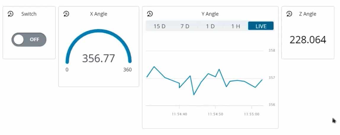
Now go back to the dashboard to check the widget. As you can see all the data are uploaded here after a certain interval. To check the working tilt the sensor checks the value on the Serial Widget screen. Similarly, to turn ON and OFF the LED, send the command from the dashboard.

So this is how you can use the Arduino IoT Cloud with ESP8266 for your project.
Video Tutorial & Complete Guide

 & Live Dashboard")


