

Overview
In this IoT project, I will show you how to make Home Automation project with ESP32 WebServer. This Home Automation project solely relies on the webpage for controlling home devices with 4 relays. Once the device is powered on, the ESP32 connects to the WiFi network and generates a webpage. Using the ESP32 IP address, you can access the Webpage. By sending on/off command from webpage, we can control 4 relays.
Previously, we developed a Home Automation project based on the ESP32 platform, utilizing platforms such as Blynk, AWS IoT Core and Arduino IoT Cloud. To enhance portability and ease of use, a custom PCB is designed specifically for this project. Comprehensive documentation, including schematics, PCB layouts, Gerber Files, a detailed Bill of Materials, and the complete Source Code, is made available.
This system is designed to operate independently, free from reliance on external IoT applications, thereby streamlining the process of integrating it into a home automation system.
Bill of Materials
For this project, we will need the following components. The component list, footprint, and quantity are given below.
| S.N. | Component | Designator | Footprint | Quantity |
|---|---|---|---|---|
| 1 | Capacitor 100nf | C1, C3, C6, C7, C8, C9, C10, C11 | CAP_0805 | 8 |
| 2 | Capacitor 10uf | C2, C4, C5 | CAP_0805 | 3 |
| 3 | Capacitor 220uF, 25V | C12 | FP-RAD-TH-D_10_0_5-L_16_1-MFG | 1 |
| 4 | Diode 1N4007 | D1, D2, D3, D4 | DIOM5027X262N | 4 |
| 5 | SP4322-01ETG | D5 | SP432201ETG | 1 |
| 6 | Optocoupler PC817C | IC1, IC3, IC4, IC5 | DIP762W60P254L458H450Q4N | 4 |
| 7 | ESP32 WROOM-32 | IC2 | ESP32WROOM3216MB | 1 |
| 8 | 2-Pin Terminal Block | J1 | 1 | |
| 9 | 3-Pin Terminal Block | J2, J3, J4, J5 | 4 | |
| 10 | Relay SRD-05VDC-SL-C | K1, K2, K3, K4 | SRD | 4 |
| 11 | LED Red | LED1, LED2, LED3, LED4, LED5 | LEDC2012X80N | 5 |
| 12 | Male Header 6 Pin | P1 | HDR1X6 | 1 |
| 13 | HLK-10M05 | PS1 | HLK10M05 | 1 |
| 14 | Transistor BC847B | Q1, Q2, Q3, Q4, Q5, Q6 | BC847B215 | 6 |
| 15 | Resistor 220R | R1, R3, R9, R11, R14, R16, R17, R19 | 805 | 8 |
| 16 | DNP | R2, R10, R15, R18 | 805 | 4 |
| 17 | Resistor 12K | R4, R12, R13 | 805 | 3 |
| 18 | Resistor 1K | R5, R7, R8, R24 | 805 | 4 |
| 19 | Resistor 470R | R6 | 805 | 1 |
| 20 | Resistor 10K | R20, R21, R22, R23 | 805 | 4 |
| 21 | Push Button Switch | S1, S2, S3, S4 | B3W1020 | 4 |
| 22 | Manual Switch (Optional) | SW1, SW2, SW3, SW4 | HDR1X2 | 4 |
| 23 | HT7333 3.3V Voltage Regulator | U1 | IC_HT7333 | 1 |
Circuit Diagram & Hardware Design
Let us take a look at the Schematic of a ESP32 Webserver Home Automation. The schematic is drawn using the Altium Designer Software.

We used SMD resistors, capacitors, and LED with the 0805 package. To convert 220V AC to 5V DC, we used an AC-to-DC Converter from Hi-Link. For providing power to ESP32 raw chip and other peripherals, a low-power LDO HT7333 IC was used. To separate the high-power line from the 3.3V circuit PC817 optocoupler IC is used. The LED5 in the circuit is used to indicate power.

Similarly the LED1, LED2, LED3 & LED4 is used to represent Relay1, Relay2, Relay3 & Relay4 output respectively. The LED5 is a power indication LED. The 4 Relays are connected to ESP32 via GPIO Pins 12, 14, 27, 26. The push buttons SW1, SW2, SW3, and SW4 are used in the manual controlling of Relays. They are connected to GPIO Pins 5, 17, 13, 16. You may attach a manual switch there and program the controller to control the circuit.
You can connect 4 home appliannces using the Relay connections at 3 Pin Terminal J2, J3. J4, J5. The 2 Pin Terminal J1 is used to supply AC Power directly to the Circuit. A Capacitor C12 of 220uF, 25V is connected to PCB stop voltage fluctuations.

To program the ESP32 raw chip, the FTDI pin is provided. We can connect an FTDI Module (USB-to-TTL Converter) to program the ESP32 Chip directly.
Project PCB Gerber File & PCB Ordering Online
We have designed the PCB using the Altium Designer Software. It took quite a lot of time fixing all the isses in the PCB but still we managed to design a complete working custom PCB. The PCB design looks like this.

Here is the 3D View of the PCB from the front side as well as from the backside.

The Gerber File for the PCB is given below. You can simply download the Gerber File and order the PCB from PCBGOGO at 1$ only.
You can use this Gerber file to order high-quality PCB for this project. To do that visit the PCBGOGO official website by clicking here: https://www.pcbgogo.com/.

You can now upload the Gerber File by choosing the Quote Now option. From these options, you can choose the Material Type, Dimensions, Quantity, Thickness, Solder Mask Color and other required parameters.

After filling all details, select your country and shipping method. Finally you can place the order.
PCB & Hardware Assembly
After ordering the PCB, it took almost 5 days and I got my PCB.

The PCB quality from PCBGOGO is superb with very high quality. That is why most people trust PCBGOGO for PCB/PCBA Services.


First solder all the SMD components like resistors, capacitors, transistors, LEDs, voltage regulators & diodes. Be careful about the SMD LED polarity, place it in the proper direction. The SMD soldering is to be done on the both sides.

After soldering all these, you can solder the ESP32 raw chip. The final stage would be soldering all the through-hole components like Optocoupler IC, terminal block, Relays, male-female headers, and AC-to-DC Converter Module.

After soldering all the components, the ESP32 Webserver Home Automation Board is ready for the test. You can upload a blink sketch by connecting a USB-to-TTL Converter Module.

Note: There were some voltage fluctuation issues in the designed PCB, so I have updated the design by adding 220uF capacitor. Also, some connection issues have been fixed. The Gerber file above is updated and the PCB would be little different from shown above. But overall the functionality is same.
Source Code/Program for Home Automation using ESP32 WebServer
Let us see the code for IoT Home Automation using ESP32 WebServer. The following code sets up an ESP32 as a simple web server for home automation. It controls four devices connected to GPIO pins, allowing their states (ON/OFF) to be toggled via a web page.
Here is the complete code. In this code make changes to the WiFi SSID and Password.
|
1 2 3 4 5 6 7 8 9 10 11 12 13 14 15 16 17 18 19 20 21 22 23 24 25 26 27 28 29 30 31 32 33 34 35 36 37 38 39 40 41 42 43 44 45 46 47 48 49 50 51 52 53 54 55 56 57 58 59 60 61 62 63 64 65 66 67 68 69 70 71 72 73 74 75 76 77 78 79 80 81 82 83 84 85 86 87 88 89 90 91 92 93 94 95 96 97 98 99 100 101 102 103 104 105 106 107 108 109 110 111 112 113 114 115 116 117 118 119 120 121 122 123 124 125 126 127 128 129 130 131 132 133 134 135 136 137 138 139 140 141 142 143 144 145 146 147 148 149 150 151 152 153 154 155 156 157 158 159 160 161 162 163 164 165 166 167 168 169 170 171 172 173 174 175 176 177 178 179 180 181 182 183 184 185 186 187 188 189 190 191 192 193 194 195 196 197 198 199 200 201 |
#include <WiFi.h> // Replace with your network credentials const char* ssid = "***************"; // Network SSID (name) const char* password = "***************"; // Network password // Set web server port number to 80 (HTTP default) WiFiServer server(80); // Variable to store the HTTP request from the client String header; // Variables to store the current state of each device (ON/OFF) String Device1State = "off"; String Device2State = "off"; String Device3State = "off"; String Device4State = "off"; // Assign each device to a GPIO pin const int Device1 = 12; const int Device2 = 14; const int Device3 = 27; const int Device4 = 26; // Variables to track the current time and last time a client made a request unsigned long currentTime = millis(); unsigned long previousTime = 0; // Define timeout time in milliseconds (2000ms = 2 seconds) const long timeoutTime = 2000; void setup() { Serial.begin(115200); // Initialize the GPIO pins for the devices as outputs and set them to LOW pinMode(Device1, OUTPUT); pinMode(Device2, OUTPUT); pinMode(Device3, OUTPUT); pinMode(Device4, OUTPUT); digitalWrite(Device1, LOW); digitalWrite(Device2, LOW); digitalWrite(Device3, LOW); digitalWrite(Device4, LOW); // Connect to Wi-Fi network with SSID and password Serial.print("Connecting to "); Serial.println(ssid); WiFi.begin(ssid, password); while (WiFi.status() != WL_CONNECTED) { delay(500); Serial.print("."); } // Print the local IP address once connected Serial.println(""); Serial.println("WiFi connected."); Serial.println("IP address: "); Serial.println(WiFi.localIP()); server.begin(); } void loop() { WiFiClient client = server.available(); // Listen for incoming clients if (client) { // If a new client connects, Serial.println("New Client."); // print a message out in the serial port String currentLine = ""; // make a String to hold incoming data from the client currentTime = millis(); previousTime = currentTime; while (client.connected() && currentTime - previousTime <= timeoutTime) { // loop while the client's connected currentTime = millis(); if (client.available()) { // if there's bytes to read from the client, char c = client.read(); // read a byte, then Serial.write(c); // print it out the serial monitor header += c; if (c == '\n') { // if the byte is a newline character // if the current line is blank, you got two newline characters in a row. // that's the end of the client HTTP request, so send a response: if (currentLine.length() == 0) { // HTTP headers always start with a response code (e.g. HTTP/1.1 200 OK) // and a content-type so the client knows what's coming, then a blank line: client.println("HTTP/1.1 200 OK"); client.println("Content-type:text/html"); client.println("Connection: close"); client.println(); // turns the Relays on and off if (header.indexOf("GET /1/on") >= 0) { Serial.println("Device 1 on"); Device1State = "on"; digitalWrite(Device1, HIGH); } else if (header.indexOf("GET /1/off") >= 0) { Serial.println("Device 1 off"); Device1State = "off"; digitalWrite(Device1, LOW); } else if (header.indexOf("GET /2/on") >= 0) { Serial.println("Device 2 on"); Device2State = "on"; digitalWrite(Device2, HIGH); } else if (header.indexOf("GET /2/off") >= 0) { Serial.println("Device 2 off"); Device2State = "off"; digitalWrite(Device2, LOW); } else if (header.indexOf("GET /3/on") >= 0) { Serial.println("Device 3 off"); Device3State = "on"; digitalWrite(Device3, HIGH); } else if (header.indexOf("GET /3/off") >= 0) { Serial.println("Device 3 off"); Device3State = "off"; digitalWrite(Device3, LOW); } else if (header.indexOf("GET /4/on") >= 0) { Serial.println("Device 4 off"); Device4State = "on"; digitalWrite(Device4, HIGH); } else if (header.indexOf("GET /4/off") >= 0) { Serial.println("Device 4 off"); Device4State = "off"; digitalWrite(Device4, LOW); } // Display the HTML web page client.println("<!DOCTYPE html><html>"); client.println("<head><meta name=\"viewport\" content=\"width=device-width, initial-scale=1\">"); client.println("<link rel=\"icon\" href=\"data:,\">"); // Enhanced CSS for a compact look client.println("<style>"); client.println("html { font-family: 'Roboto', sans-serif; background: #f5f5f5; display: flex; justify-content: center; align-items: center; height: 100vh; margin: 0; }"); client.println("body { max-width: 600px; background: #fff; padding: 20px; margin: 20px; border-radius: 5px; box-shadow: 0 0 10px rgba(0, 0, 0, 0.1); }"); client.println("h1 { color: #333; text-align: center; }"); client.println(".device { background: linear-gradient(to right, #dae2f8, #d6a4a4); padding: 15px; margin: 10px 0; border-radius: 10px; box-shadow: 0 4px 8px rgba(0, 0, 0, 0.1); text-align: center; }"); // Reduced padding and margin client.println("p { font-size: 18px; color: #555; margin: 10px 0; }"); client.println(".button { border: none; padding: 15px 35px; text-align: center;"); // Slightly reduced padding client.println("text-decoration: none; display: inline-block; font-size: 22px; margin: 10px; cursor: pointer; border-radius: 5px; transition: all 0.3s ease; box-shadow: 0 2px 4px rgba(0, 0, 0, 0.2); }"); client.println(".button:hover { box-shadow: 0 4px 8px rgba(0, 0, 0, 0.4); }"); client.println(".button-on { background-color: #4CAF50; color: white; }"); client.println(".button-off { background-color: #f44336; color: white; }"); client.println("</style></head>"); // Web Page Heading client.println("<body><h1>Smart Home Automation</h1>"); // Display current state, and ON/OFF buttons for Relay 1 client.println("<div class=\"device\"><p>Device 1 - State " + Device1State + "</p>"); if (Device1State == "off") { client.println("<a href=\"/1/on\"><button class=\"button button-on\">ON</button></a>"); } else { client.println("<a href=\"/1/off\"><button class=\"button button-off\">OFF</button></a>"); } client.println("</div>"); // Display current state, and ON/OFF buttons for Relay 2 client.println("<div class=\"device\"><p>Device 2 - State " + Device2State + "</p>"); if (Device2State == "off") { client.println("<a href=\"/2/on\"><button class=\"button button-on\">ON</button></a>"); } else { client.println("<a href=\"/2/off\"><button class=\"button button-off\">OFF</button></a>"); } client.println("</div>"); // Display current state, and ON/OFF buttons for Relay 3 client.println("<div class=\"device\"><p>Device 3 - State " + Device3State + "</p>"); if (Device3State == "off") { client.println("<a href=\"/3/on\"><button class=\"button button-on\">ON</button></a>"); } else { client.println("<a href=\"/3/off\"><button class=\"button button-off\">OFF</button></a>"); } client.println("</div>"); // Display current state, and ON/OFF buttons for Relay 4 client.println("<div class=\"device\"><p>Device 4 - State " + Device4State + "</p>"); if (Device4State == "off") { client.println("<a href=\"/4/on\"><button class=\"button button-on\">ON</button></a>"); } else { client.println("<a href=\"/4/off\"><button class=\"button button-off\">OFF</button></a>"); } client.println("</div>"); client.println("</body></html>"); // The HTTP response ends with another blank line client.println(); // Break out of the while loop break; } else { // if you got a newline, then clear currentLine currentLine = ""; } } else if (c != '\r') { // if you got anything else but a carriage return character, currentLine += c; // add it to the end of the currentLine } } } // Clear the header variable header = ""; // Close the connection client.stop(); Serial.println("Client disconnected."); Serial.println(""); } } |
To program the ESP32 Raw Chip, connect the FTDI Module to your FTDI Pin of the PCB.

Then go to the tools & select ESP32 Dev Module that you are using for this project. Also, select the COM port. Then click on the upload option to upload the code to the ESP32 Chip.
Note: While uploading the code disconnect the relay from the power source.
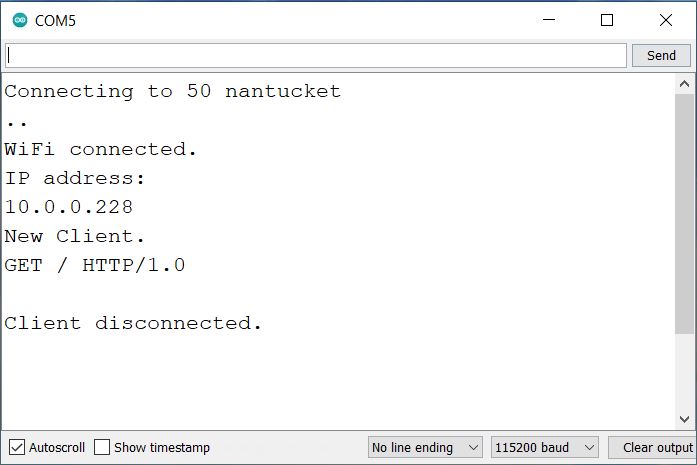
Once the code uploading is done, open the Serial Monitor. The ESP32 will try connecting to the WiFi Network. Once it gets connected to the WiFi Network, the Serial Monitor will display the IP Address of ESP32.

Now remove the FTDI Module connection and power the device using the AC Supply.
Testing ESP32 Webserver Home Automation Project
Let us test the working of the project. Testing the ESP32 Webserver Home Automation project involves verifying that the ESP32 correctly interprets HTTP requests from the web interface and controls the connected devices as expected. Here’s how you can do the testing.
Ensure the ESP32 is powered correctly, with stable voltage and current. Check that the ESP32 connects to the WiFi network. The serial monitor should display the assigned IP address after connecting.
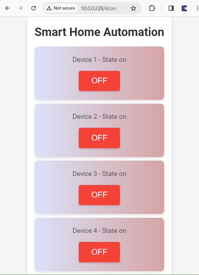
Enter the IP address displayed in the serial monitor into a web browser. The home automation control interface should load. The Webpage looks beautiful and very stylish.
Click the buttons on the web interface to send ON/OFF commands to each device.
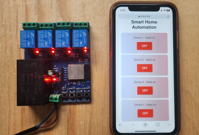
Observe the connected devices (relays, LEDs, etc.) to verify they respond correctly to the commands from the web interface.

Ensure that the web interface correctly displays the current state of each device after sending commands. This is how you can control Home Appliances with Automation using the ESP32 WebServer.
 & Live Dashboard")


