

Overview
In this project, we will be interfacing MAX30102 Pulse Oximeter Sensor with Arduino to measure Heart Rate (BPM) & Blood Oxygen Concentration (SP02). The Pulse Rate value and Blood Oxygen value will be displayed on 0.96″ OLED Display.
The MAX30102 is an integrated pulse oximetry and heart-rate monitor biosensor module based on PPG (PhotoPlethysmoGraphy). The MAX30102 pulse Oximeter Sensor can be integrated with any microcontroller like Arduino, ESP8266, ESP32, STM32 or Raspberry Pi Pico using the I2C communication protocol. BPM stands for ‘beats per minute,’ which typically range from 65 to 75 during rest for an average person. Athletes may have BPM rates lower than this range. SpO2 represents the oxygen saturation level, which, for a normal individual, is above 95%.
Earlier, we used MAX30100 Pulse Oximeter sensor but MAX30102 is better & précised version of same sensor. This project covers the MAX30102 introduction, pinout, working, connection & applications in detail. At the end, the sensor can be used in real-time application project.
Bill of Materials
Following are the components that we need for this project. The components can be purchased from the given links.
| S.N. | Components | Quantity | Purchase Link |
|---|---|---|---|
| 1 | Arduino UNO Board | 1 | Amazon | AliExpress | SunFounder |
| 2 | MAX30102 Pulse Oximeter | 1 | Amazon | AliExpress | SunFounder |
| 3 | 0.96" SSD1306 I2C OLED Display | 1 | Amazon | AliExpress | SunFounder |
| 4 | Push Button Switch | 1 | Amazon | AliExpress | SunFounder |
| 5 | Jumper Wires | 10 | Amazon | AliExpress | SunFounder |
| 6 | Breadboard | 1 | Amazon | AliExpress | SunFounder |
MAX30102 Pulse Oximeter Sensor
The MAX30102 is an integrated pulse oximetry and heart-rate monitor module.
Not only heart rate, this device can also measure the concentration of oxygen in blood. This is a sensor designed by Analog Devices. The module is available in various board configurations designed by different manufacturers.

It includes internal LEDs, photodetectors, optical elements, and low-noise electronics with ambient light rejection. The MAX30102 provides a complete system solution to ease the design-in process for mobile and wearable devices.
MAX30102 Functional Diagram with Detailed Description
Lets take a look at the design part of the MAX30102 Pulse Oximeter Sensor Module. The sensor is designed for the demanding requirements of wearable devices. The device maintains a very small solution size without sacrificing optical or electrical performance. Here is its block diagram.
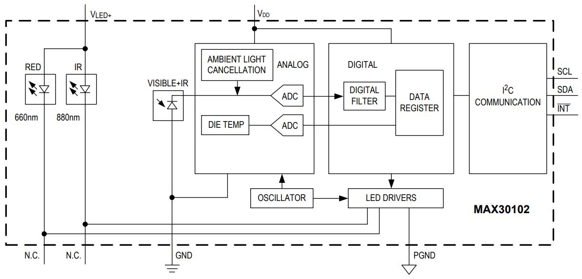
The MAX30102 is fully adjustable through software registers, and the digital output data can be stored in a 32-deep FIFO within the IC. The FIFO allows the MAX30102 to be connected to a microcontroller or processor on a shared bus, where the data is not being read continuously from the MAX30102’s registers. It has a fixed I2C address of 0xAE (for write operation) and 0xAF (for read operation). You may refer to MAX30102 Datasheet for more information.
SpO2 Subsystem
The SpO2 subsystem of the MAX30102 contains ambient light cancellation (ALC), a continuous-time sigma-delta ADC, and a proprietary discrete time filter. The ALC has an internal Track/Hold circuit to cancel ambient light and increase the effective dynamic range. The SpO2 ADC has
programmable full-scale ranges from 2µA to 16µA. The ALC can cancel up to 200µA of ambient current. The internal ADC is a continuous time oversampling sigma-delta converter with 18-bit resolution. The ADC sampling rate is 10.24MHz. The ADC output data rate can be programmed from 50sps (samples per second) to 3200sps.
Temperature Sensor
The MAX30102 has an on-chip temperature sensor for calibrating the temperature dependence of the SpO2 subsystem. The temperature sensor has an inherent resolution of 0.0625°C. The device output data is relatively insensitive to the wavelength of the IR LED, where the Red LED’s wavelength is critical to correct interpretation of the data. An SpO2 algorithm used with the MAX30102 output signal can compensate for the associated SpO2 error with ambient temperature changes.
LED Driver
The MAX30102 integrates Red and IR LED drivers to modulate LED pulses for SpO2 and HR measurements. The LED current can be programmed from 0 to 50mA with proper supply voltage. The LED pulse width can be programmed from 69µs to 411µs to allow the algorithm to optimize SpO2 and HR accuracy and power consumption based on use cases.
Technical Specifications
| Maximum Current Consumption | 6mA |
| Voltage | 3.3-5V |
| Sample Rate | 50Hz – 3200Hz |
| I2C Address | 0xAE (Read) & 0xAF (Write) |
| Temperature Range | -40°C to +85°C |
| Temperature Accuracy | ±1˚C |
| ADC Resolution | 18 bits |
| IR LED peak wavelength | 880nm |
| Red LED peak wavelength | 660nm |
MAX30102 Power Requirements
The MAX30102 IC operates on a single 1.8V power supply but a separate 3.3V power supply is required for the internal LEDs. So the module comes with 3.3V and 1.8V regulators.
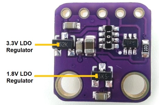
The module can be shut down through software with zero standby current, allowing the power rails to remain powered at all times.
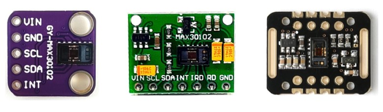
MAX30102 Module Pinout
Most of the MAX30102 Module has 5 Pins while some have 7 pins which are explained below:
| Pin | Description |
|---|---|
| VIN | This pin is used to supply power to the sensor. This sensor is powered on at 3.3-5V. |
| SCL | This is the I2C serial clock pin. |
| SDA | This is the I2C serial data pin. |
| INT | This is the active low interrupt pin. It is pulled HIGH by the onboard resistor but when an interrupt occurs it goes LOW until the interrupt clears. |
| IRD | IR LED Cathode and LED Driver Connection Point |
| RD | Red LED Cathode and LED Driver Connection Point |
| GND | Ground Pin |
How MAX30102 Pulse Oximeter Sensor Works?
Let us understand the working of MAX30102 Pulse Oximeter Sensor.
Principle
The MAX30102 works by shining both lights onto the finger or earlobe (or essentially anywhere where the skin isn’t too thick, so both lights can easily penetrate the tissue) and measuring the amount of reflected light using a photodetector. This method of pulse detection through light is called Photoplethysmogram.
The working of MAX30102 can be divided into two parts: Heart Rate Measurement and Pulse Oximetry (measuring the oxygen level of the blood).
Heart Rate Measurement
The oxygenated hemoglobin (HbO2) in the arterial blood has the characteristic of absorbing IR light. The redder the blood (the higher the hemoglobin), the more IR light is absorbed.

As the blood is pumped through the finger with each heartbeat, the amount of reflected light changes, creating a changing waveform at the output of the photodetector. As you continue to shine light and take photodetector readings, you quickly start to get a heart-beat (HR) pulse reading.
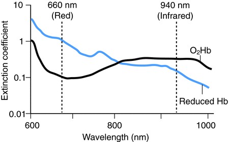
Pulse Oximetry
Pulse oximetry is based on the principle that the amount of RED and IR light absorbed varies depending on the amount of oxygen in your blood.
Interfacing MAX30102 Pulse Oximeter Sensor with Arduino
Let us interface the MAX30102 Pulse Oximeter Sensor with Arduino & find out how we can use it for Heart Rate Blood Oxygen measurement.
Wiring up a MAX30102 Module to an Arduino
Connecting a MAX30102 module to an Arduino board allows you to experiment with monitoring heart rate and blood oxygen levels. Here is the connection diagram.
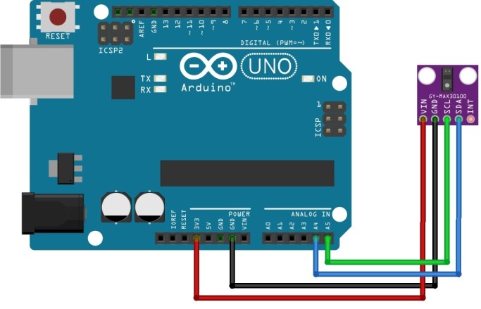
Connect the VIN pin & GND Pin of the MAX30102 to the 3.3V & GND pin on your Arduino. Similarly Connect the SCL & SDA pin of the MAX30102 to the A5 & A4 pin on the Arduino Uno respectively.
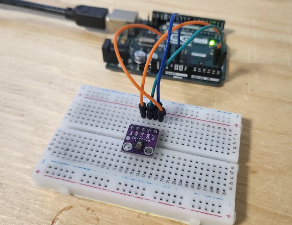
You can use a breadboard and jumper wires for assembly.
Measuring Heart Rate, Blood Oxygen & Temperature with MAX30102 & Arduino
In the coding part of this project, we can use the MAX30102 Arduino library to measure the value of Heart Rate in BPM, Blood Oxygen in percentage and Temperature in degree Celsius. Before that, we need to install the MAX30102 library.
MAX30102 Arduino Library Installation
There are multiple libraries available for MAX30102 Sensor to measure the heart beat, blood oxygen and temperature. Out of all these libraries, the library from Sparkfun Electronics is the most popular one.
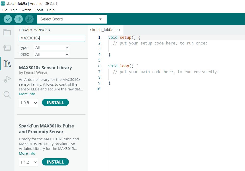
To install the library, search by typing MAX3010x. Look for SparkFun MAX3010x Pulse and Proximity Sensor Library. Click on install to install the library.
Example 1: Measuring Heart-Rate (BPM) with MAX30102 & Arduino
This code initializes a MAX30105 sensor on an Arduino to measure heart rate in beats per minute, averages the readings for accuracy, and outputs the data along with the infrared sensor value to the serial monitor, indicating whether a finger is placed on the sensor.
|
1 2 3 4 5 6 7 8 9 10 11 12 13 14 15 16 17 18 19 20 21 22 23 24 25 26 27 28 29 30 31 32 33 34 35 36 37 38 39 40 41 42 43 44 45 46 47 48 49 50 51 52 53 54 55 56 57 58 59 60 61 62 63 64 65 66 67 68 69 |
// Include necessary libraries for communication and for the MAX30105 sensor #include <Wire.h> #include "MAX30105.h" #include "heartRate.h" // Create an instance of the MAX30105 class to interact with the sensor MAX30105 particleSensor; // Define the size of the rates array for averaging BPM; can be adjusted for smoother results const byte RATE_SIZE = 4; // Increase this for more averaging. 4 is a good starting point. byte rates[RATE_SIZE]; // Array to store heart rate readings for averaging byte rateSpot = 0; // Index for inserting the next heart rate reading into the array long lastBeat = 0; // Timestamp of the last detected beat, used to calculate BPM float beatsPerMinute; // Calculated heart rate in beats per minute int beatAvg; // Average heart rate after processing multiple readings void setup() { Serial.begin(115200); // Start serial communication at 115200 baud rate Serial.println("Initializing..."); // Attempt to initialize the MAX30105 sensor. Check for a successful connection and report. if (!particleSensor.begin(Wire, I2C_SPEED_FAST)) { // Start communication using fast I2C speed Serial.println("MAX30102 was not found. Please check wiring/power. "); while (1); // Infinite loop to halt further execution if sensor is not found } Serial.println("Place your index finger on the sensor with steady pressure."); particleSensor.setup(); // Configure sensor with default settings for heart rate monitoring particleSensor.setPulseAmplitudeRed(0x0A); // Set the red LED pulse amplitude (intensity) to a low value as an indicator particleSensor.setPulseAmplitudeGreen(0); // Turn off the green LED as it's not used here } void loop() { long irValue = particleSensor.getIR(); // Read the infrared value from the sensor if (checkForBeat(irValue) == true) { // Check if a heart beat is detected long delta = millis() - lastBeat; // Calculate the time between the current and last beat lastBeat = millis(); // Update lastBeat to the current time beatsPerMinute = 60 / (delta / 1000.0); // Calculate BPM // Ensure BPM is within a reasonable range before updating the rates array if (beatsPerMinute < 255 && beatsPerMinute > 20) { rates[rateSpot++] = (byte)beatsPerMinute; // Store this reading in the rates array rateSpot %= RATE_SIZE; // Wrap the rateSpot index to keep it within the bounds of the rates array // Compute the average of stored heart rates to smooth out the BPM beatAvg = 0; for (byte x = 0 ; x < RATE_SIZE ; x++) beatAvg += rates[x]; beatAvg /= RATE_SIZE; } } // Output the current IR value, BPM, and averaged BPM to the serial monitor Serial.print("IR="); Serial.print(irValue); Serial.print(", BPM="); Serial.print(beatsPerMinute); Serial.print(", Avg BPM="); Serial.print(beatAvg); // Check if the sensor reading suggests that no finger is placed on the sensor if (irValue < 50000) Serial.print(" No finger?"); Serial.println(); } |
From the Tools Menu, Select Arduino UNO Board and the COM Port. Click on upload button to upload the code. Once code uploading is done, the MAX30102 Pulse Oximeter Sensor is ready to test.

Now keep your finger on the sensor as steady as possible and wait a few seconds for the readings to appear. The Serial monitor will display this reading.
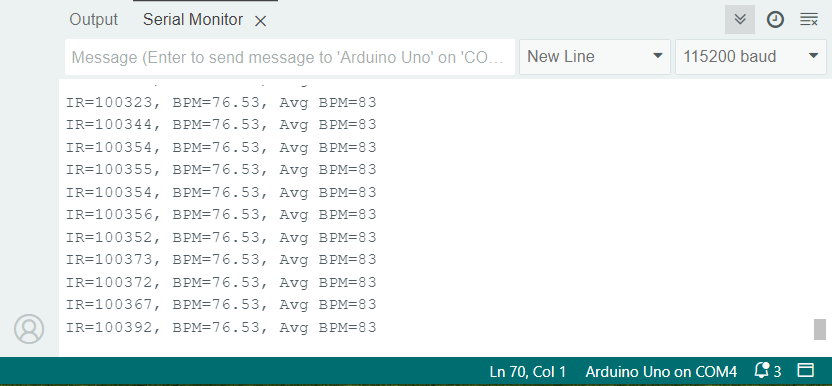
For consistent blood flow and reliable sensor data, maintain constant pressure. Applying the optimal pressure on the pulse sensor — not too hard to avoid squeezing out blood and not too light to prevent noise from movement and ambient light.
Example 2: Measuring Blood Oxygen (SpO2) with MAX30102 & Arduino
This code reads heart rate and oxygen levels from a finger using the MAX30105 sensor, then sends this information to a Serial Screen. It dynamically adjusts the data buffer based on the Arduino model to accommodate memory constraints.
|
1 2 3 4 5 6 7 8 9 10 11 12 13 14 15 16 17 18 19 20 21 22 23 24 25 26 27 28 29 30 31 32 33 34 35 36 37 38 39 40 41 42 43 44 45 46 47 48 49 50 51 52 53 54 55 56 57 58 59 60 61 62 63 64 65 66 67 68 69 70 71 72 73 74 75 76 77 78 79 80 81 82 83 84 85 86 87 88 89 90 91 92 93 94 95 96 97 98 99 100 101 102 103 104 105 106 107 108 |
#include <Wire.h> #include "MAX30105.h" // Include MAX30105 sensor library #include "spo2_algorithm.h" // Include SpO2 calculation algorithm MAX30105 particleSensor; // Create an instance of the MAX30105 class #define MAX_BRIGHTNESS 255 // Define maximum LED brightness // Adjust buffer size based on the microcontroller's memory capacity #if defined(__AVR_ATmega328P__) || defined(__AVR_ATmega168__) uint16_t irBuffer[100]; // Buffer for IR data (16-bit for memory-limited devices) uint16_t redBuffer[100]; // Buffer for red LED data #else uint32_t irBuffer[100]; // Buffer for IR data (32-bit for devices with more memory) uint32_t redBuffer[100]; // Buffer for red LED data #endif int32_t bufferLength = 100; // Length of data buffer int32_t spo2; // Variable to store calculated SpO2 value int8_t validSPO2; // Flag indicating if SpO2 calculation is valid int32_t heartRate; // Variable to store calculated heart rate int8_t validHeartRate; // Flag indicating if heart rate calculation is valid byte pulseLED = 11; // LED pin for pulse indication (must support PWM) byte readLED = 13; // LED pin to indicate data read operation void setup() { Serial.begin(115200); // Initialize serial communication pinMode(pulseLED, OUTPUT); // Set pulseLED as output pinMode(readLED, OUTPUT); // Set readLED as output // Initialize MAX30105 sensor if (!particleSensor.begin(Wire, I2C_SPEED_FAST)) { Serial.println(F("MAX30105 not found. Check wiring/power.")); while (1); // Halt execution if sensor not found } Serial.println(F("Attach sensor to finger. Press key to start.")); while (Serial.available() == 0); // Wait for user input to proceed Serial.read(); // Clear the serial buffer // Sensor configuration settings byte ledBrightness = 60; // LED brightness (0-255) byte sampleAverage = 4; // Averaging (1, 2, 4, 8, 16, 32) byte ledMode = 2; // LED mode (1=Red, 2=Red+IR, 3=Red+IR+Green) byte sampleRate = 100; // Sampling rate (50, 100, 200, 400, 800, 1000, 1600, 3200) int pulseWidth = 411; // Pulse width (69, 118, 215, 411) int adcRange = 4096; // ADC range (2048, 4096, 8192, 16384) // Apply configuration settings to the sensor particleSensor.setup(ledBrightness, sampleAverage, ledMode, sampleRate, pulseWidth, adcRange); } void loop() { // Collect 100 samples and output raw red and IR data for (byte i = 0; i < bufferLength; i++) { while (!particleSensor.available()) particleSensor.check(); // Wait for new data redBuffer[i] = particleSensor.getRed(); // Store red LED data irBuffer[i] = particleSensor.getIR(); // Store IR data particleSensor.nextSample(); // Move to next sample Serial.print(F("red=")); Serial.print(redBuffer[i], DEC); Serial.print(F(", ir=")); Serial.println(irBuffer[i], DEC); } // Calculate heart rate and SpO2 from the first 100 samples maxim_heart_rate_and_oxygen_saturation(irBuffer, bufferLength, redBuffer, &spo2, &validSPO2, &heartRate, &validHeartRate); // Continuously update heart rate and SpO2 values with new samples while (1) { // Shift the last 75 samples to the beginning and fill the remaining with new data for (byte i = 25; i < 100; i++) { redBuffer[i - 25] = redBuffer[i]; irBuffer[i - 25] = irBuffer[i]; } // Collect new samples to refill the buffer for (byte i = 75; i < 100; i++) { while (!particleSensor.available()) particleSensor.check(); // Wait for new data digitalWrite(readLED, !digitalRead(readLED)); // Blink LED with each data read redBuffer[i] = particleSensor.getRed(); // Store new red data irBuffer[i] = particleSensor.getIR(); // Store new IR data particleSensor.nextSample(); // Move to next sample // Output raw data and calculated heart rate/SpO2 values Serial.print(F("red=")); Serial.print(redBuffer[i], DEC); Serial.print(F(", ir=")); Serial.print(irBuffer[i], DEC); Serial.print(F(", HR=")); Serial.print(heartRate, DEC); Serial.print(F(", HRvalid=")); Serial.print(validHeartRate, DEC); Serial.print(F(", SPO2=")); Serial.print(spo2, DEC); Serial.print(F(", SPO2Valid=")); Serial.println(validSPO2, DEC); } // Recalculate heart rate and SpO2 with the updated buffer maxim_heart_rate_and_oxygen_saturation(irBuffer, bufferLength, redBuffer, &spo2, &validSPO2, &heartRate, &validHeartRate); } } |
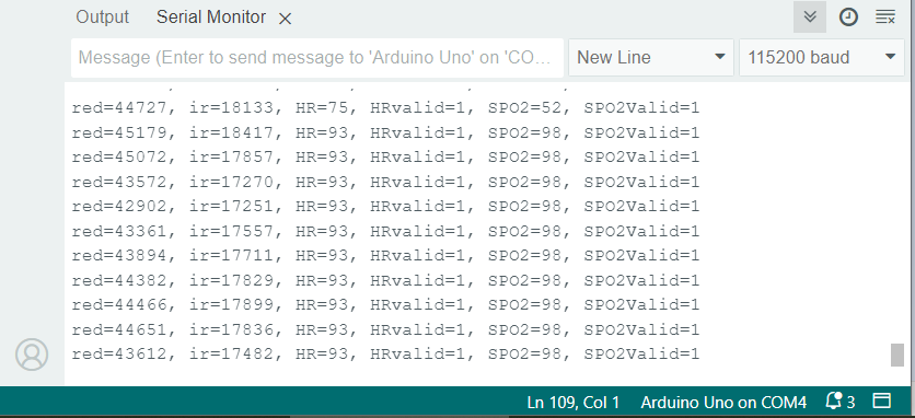
After uploading the code, put your finger on the MAX30102 Pulse Oximeter Sensor. The Serial Monitor will display the Blood Oxygen reading in percentage.
Example 3: Measuring Temperature with MAX30102 & Arduino
The following code initializes a MAX30105 sensor to measure temperature, then continuously reads and displays the temperature in both Celsius and Fahrenheit on the serial monitor.
|
1 2 3 4 5 6 7 8 9 10 11 12 13 14 15 16 17 18 19 20 21 22 23 24 25 26 27 28 29 30 |
#include <Wire.h> #include "MAX30105.h" // Include library for MAX30105 sensor MAX30105 particleSensor; // Create an instance of the MAX30105 class void setup() { Serial.begin(115200); // Start serial communication at 9600 baud rate Serial.println("Initializing..."); // Check if MAX30105 sensor is properly connected if (!particleSensor.begin(Wire, I2C_SPEED_FAST)) { // Initialize sensor with fast I2C speed Serial.println("MAX30102 was not found. Please check wiring/power. "); while (1); // Infinite loop if sensor is not found } particleSensor.setup(0); // Initialize sensor with LEDs turned off to prevent local heating particleSensor.enableDIETEMPRDY(); // Enable temperature ready interrupt for reading temperature } void loop() { float temperature = particleSensor.readTemperature(); // Read temperature in Celsius Serial.print("temperatureC="); // Print temperature in Celsius Serial.print(temperature, 4); // Print with 4 decimal places float temperatureF = particleSensor.readTemperatureF(); // Convert temperature to Fahrenheit Serial.print(" temperatureF="); // Print temperature in Fahrenheit Serial.print(temperatureF, 4); // Print with 4 decimal places Serial.println(); // New line for readability } |
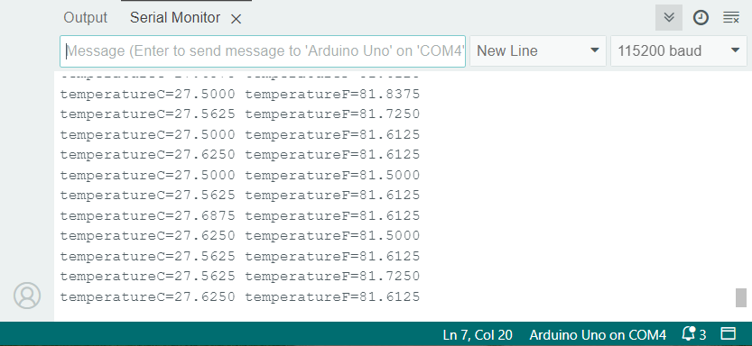
Open the Serial Monitor after uploading the code. The Serial Monitor will show the value of Temperature in both Celcius and Fahrenheit Scale.
Making a Portable Pulse Oximeter with OLED Display
Let us make a portable Pulse Oximeter by interfacing OLED Display & MAX30102 with Arduino Nano. The OLED will display the real-time Heart Rate and Oxygen Saturation value.
Circuit Diagram & Connection
In the hardware part, we will use 0.96″ I2C OLED Display with SSD1306 Driver. We will also use a push button switch here to control the display part. Here is the simple connection diagram.

Connect the SSD1306 OLED Display to I2C Pins of Arduino Nano. Also connect the Push button switch to digital pin 3 of the Arduino and its other terminal to the GND.
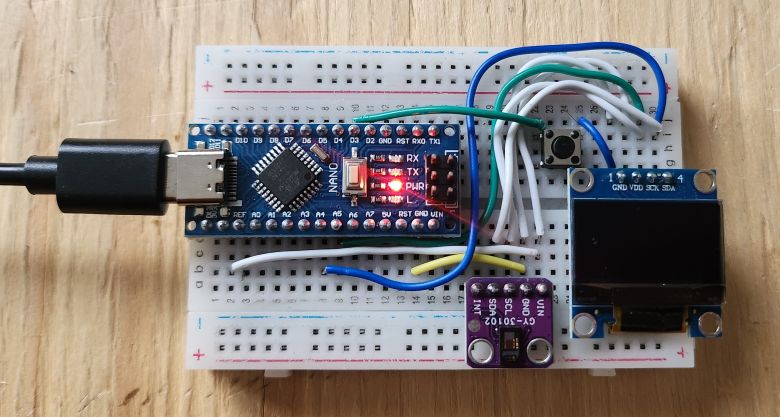
While making connection on a breadboard, you need a lot of wiring. Therefore if you can make a custom PCB to avoid wiring, it would be better.
Source Code/Program
Let us see the programming part of the portable pulse oximeter. The following code integrates an OLED display and a MAX30102 sensor with an Arduino to measure and display heart rate and blood oxygen saturation (SpO2) levels.
It includes functionality to filter signal noise for more accurate readings, dynamically adjust the display based on sensor data, and enter a low-power mode when the sensor is not in use. The program also offers user interaction through a button to change display modes and uses EEPROM for saving user preferences.
The code requires a custom made library. The library contains all the header files for OLED Display and MAX30102 Sensor. First download the MAX30102 & OLED Library and add it to your Arduino Library folder.
Copy the following code and paste it on your Arduino IDE. Then finally you can upload the code.
|
1 2 3 4 5 6 7 8 9 10 11 12 13 14 15 16 17 18 19 20 21 22 23 24 25 26 27 28 29 30 31 32 33 34 35 36 37 38 39 40 41 42 43 44 45 46 47 48 49 50 51 52 53 54 55 56 57 58 59 60 61 62 63 64 65 66 67 68 69 70 71 72 73 74 75 76 77 78 79 80 81 82 83 84 85 86 87 88 89 90 91 92 93 94 95 96 97 98 99 100 101 102 103 104 105 106 107 108 109 110 111 112 113 114 115 116 117 118 119 120 121 122 123 124 125 126 127 128 129 130 131 132 133 134 135 136 137 138 139 140 141 142 143 144 145 146 147 148 149 150 151 152 153 154 155 156 157 158 159 160 161 162 163 164 165 166 167 168 169 170 171 172 173 174 175 176 177 178 179 180 181 182 183 184 185 186 187 188 189 190 191 192 193 194 195 196 197 198 199 200 201 202 203 204 205 206 207 208 209 210 211 212 213 214 215 216 217 218 219 220 221 222 223 224 225 226 227 228 229 230 231 232 233 234 235 236 237 238 239 240 241 242 243 244 245 246 247 248 249 250 251 252 253 254 255 256 257 258 259 260 261 262 263 264 265 266 267 268 269 270 271 272 273 274 275 276 277 278 279 280 281 282 283 284 285 286 287 288 289 290 291 292 293 294 295 296 297 298 299 300 301 302 303 304 305 306 307 308 309 310 311 312 313 314 315 316 317 318 319 320 321 322 |
#include "ssd1306h.h" #include "MAX30102.h" #include "Pulse.h" #include <avr/pgmspace.h> #include <EEPROM.h> #include <avr/sleep.h> #ifndef cbi #define cbi(sfr, bit) (_SFR_BYTE(sfr) &= ~_BV(bit)) #endif #ifndef sbi #define sbi(sfr, bit) (_SFR_BYTE(sfr) |= _BV(bit)) #endif SSD1306 oled; MAX30102 sensor; Pulse pulseIR; Pulse pulseRed; MAFilter bpm; #define LED LED_BUILTIN #define BUTTON 3 #define OPTIONS 7 static const uint8_t heart_bits[] PROGMEM = { 0x00, 0x00, 0x38, 0x38, 0x7c, 0x7c, 0xfe, 0xfe, 0xfe, 0xff, 0xfe, 0xff, 0xfc, 0x7f, 0xf8, 0x3f, 0xf0, 0x1f, 0xe0, 0x0f, 0xc0, 0x07, 0x80, 0x03, 0x00, 0x01, 0x00, 0x00, 0x00, 0x00, 0x00, 0x00 }; //spo2_table is approximated as -45.060*ratioAverage* ratioAverage + 30.354 *ratioAverage + 94.845 ; const uint8_t spo2_table[184] PROGMEM = { 95, 95, 95, 96, 96, 96, 97, 97, 97, 97, 97, 98, 98, 98, 98, 98, 99, 99, 99, 99, 99, 99, 99, 99, 100, 100, 100, 100, 100, 100, 100, 100, 100, 100, 100, 100, 100, 100, 100, 100, 100, 100, 100, 100, 99, 99, 99, 99, 99, 99, 99, 99, 98, 98, 98, 98, 98, 98, 97, 97, 97, 97, 96, 96, 96, 96, 95, 95, 95, 94, 94, 94, 93, 93, 93, 92, 92, 92, 91, 91, 90, 90, 89, 89, 89, 88, 88, 87, 87, 86, 86, 85, 85, 84, 84, 83, 82, 82, 81, 81, 80, 80, 79, 78, 78, 77, 76, 76, 75, 74, 74, 73, 72, 72, 71, 70, 69, 69, 68, 67, 66, 66, 65, 64, 63, 62, 62, 61, 60, 59, 58, 57, 56, 56, 55, 54, 53, 52, 51, 50, 49, 48, 47, 46, 45, 44, 43, 42, 41, 40, 39, 38, 37, 36, 35, 34, 33, 31, 30, 29, 28, 27, 26, 25, 23, 22, 21, 20, 19, 17, 16, 15, 14, 12, 11, 10, 9, 7, 6, 5, 3, 2, 1 } ; int getVCC() { //reads internal 1V1 reference against VCC #if defined(__AVR_ATmega1284P__) ADMUX = _BV(REFS0) | _BV(MUX4) | _BV(MUX3) | _BV(MUX2) | _BV(MUX1); // For ATmega1284 #else ADMUX = _BV(REFS0) | _BV(MUX3) | _BV(MUX2) | _BV(MUX1); // For ATmega328 #endif delay(2); // Wait for Vref to settle ADCSRA |= _BV(ADSC); // Convert while (bit_is_set(ADCSRA, ADSC)); uint8_t low = ADCL; unsigned int val = (ADCH << 8) | low; //discard previous result ADCSRA |= _BV(ADSC); // Convert while (bit_is_set(ADCSRA, ADSC)); low = ADCL; val = (ADCH << 8) | low; return (((long)1024 * 1100) / val) / 100; } void print_digit(int x, int y, long val, char c = ' ', uint8_t field = 3, const int BIG = 2) { uint8_t ff = field; do { char ch = (val != 0) ? val % 10 + '0' : c; oled.drawChar( x + BIG * (ff - 1) * 6, y, ch, BIG); val = val / 10; --ff; } while (ff > 0); } /* Record, scale and display PPG Wavefoem */ const uint8_t MAXWAVE = 72; class Waveform { public: Waveform(void) { wavep = 0; } void record(int waveval) { waveval = waveval / 8; // scale to fit in byte 缩放以适合字节 waveval += 128; //shift so entired waveform is +ve waveval = waveval < 0 ? 0 : waveval; waveform[wavep] = (uint8_t) (waveval > 255) ? 255 : waveval; wavep = (wavep + 1) % MAXWAVE; } void scale() { uint8_t maxw = 0; uint8_t minw = 255; for (int i = 0; i < MAXWAVE; i++) { maxw = waveform[i] > maxw ? waveform[i] : maxw; minw = waveform[i] < minw ? waveform[i] : minw; } uint8_t scale8 = (maxw - minw) / 4 + 1; //scale * 8 to preserve precision uint8_t index = wavep; for (int i = 0; i < MAXWAVE; i++) { disp_wave[i] = 31 - ((uint16_t)(waveform[index] - minw) * 8) / scale8; index = (index + 1) % MAXWAVE; } } void draw(uint8_t X) { for (int i = 0; i < MAXWAVE; i++) { uint8_t y = disp_wave[i]; oled.drawPixel(X + i, y); if (i < MAXWAVE - 1) { uint8_t nexty = disp_wave[i + 1]; if (nexty > y) { for (uint8_t iy = y + 1; iy < nexty; ++iy) oled.drawPixel(X + i, iy); } else if (nexty < y) { for (uint8_t iy = nexty + 1; iy < y; ++iy) oled.drawPixel(X + i, iy); } } } } private: uint8_t waveform[MAXWAVE]; uint8_t disp_wave[MAXWAVE]; uint8_t wavep = 0; } wave; int beatAvg; int SPO2, SPO2f; int voltage; bool filter_for_graph = false; bool draw_Red = false; uint8_t pcflag = 0; uint8_t istate = 0; uint8_t sleep_counter = 0; void button(void) { pcflag = 1; } void checkbutton() { if (pcflag && !digitalRead(BUTTON)) { istate = (istate + 1) % 4; filter_for_graph = istate & 0x01; draw_Red = istate & 0x02; EEPROM.write(OPTIONS, filter_for_graph); EEPROM.write(OPTIONS + 1, draw_Red); } pcflag = 0; } void Display_5() { if (pcflag && !digitalRead(BUTTON)) { draw_oled(5); delay(1100); } pcflag = 0; } void go_sleep() { oled.fill(0); oled.off(); delay(10); sensor.off(); delay(10); cbi(ADCSRA, ADEN); // disable adc delay(10); pinMode(0, INPUT); pinMode(2, INPUT); set_sleep_mode(SLEEP_MODE_PWR_DOWN); sleep_mode(); // sleep until button press // cause reset setup(); } void draw_oled(int msg) { oled.firstPage(); do { switch (msg) { case 0: oled.drawStr(10, 0, F("Device error"), 1); break; case 1: oled.drawStr(0, 0, F("PLACE YOUR"), 2); oled.drawStr(25, 18, F("FINGER"), 2); break; case 2: print_digit(86, 0, beatAvg); oled.drawStr(0, 3, F("PULSE RATE"), 1); oled.drawStr(11, 17, F("OXYGEN"), 1); oled.drawStr(0, 25, F("SATURATION"), 1); print_digit(73, 16, SPO2f, ' ', 3, 2); oled.drawChar(116, 16, '%', 2); break; case 3: oled.drawStr(33, 0, F("Pulse"), 2); oled.drawStr(17, 15, F("Oximeter"), 2); //oled.drawXBMP(6,8,16,16,heart_bits); break; case 4: oled.drawStr(28, 12, F("OFF IN"), 1); oled.drawChar(76, 12, 10 - sleep_counter / 10 + '0'); oled.drawChar(82, 12, 's'); break; case 5: oled.drawStr(0, 0, F("Avg Pulse"), 1); print_digit(75, 0, beatAvg); oled.drawStr(0, 15, F("AVG OXYGEN"), 1); oled.drawStr(0, 22, F("saturation"), 1); print_digit(75, 15, SPO2); break; } } while (oled.nextPage()); } void setup(void) { pinMode(LED, OUTPUT); pinMode(BUTTON, INPUT_PULLUP); filter_for_graph = EEPROM.read(OPTIONS); draw_Red = EEPROM.read(OPTIONS + 1); oled.init(); oled.fill(0x00); draw_oled(3); delay(3000); if (!sensor.begin()) { draw_oled(0); while (1); } sensor.setup(); attachInterrupt(digitalPinToInterrupt(BUTTON), button, CHANGE); } long lastBeat = 0; //Time of the last beat long displaytime = 0; //Time of the last display update bool led_on = false; void loop() { sensor.check(); long now = millis(); //start time of this cycle if (!sensor.available()) return; uint32_t irValue = sensor.getIR(); uint32_t redValue = sensor.getRed(); sensor.nextSample(); if (irValue < 5000) { voltage = getVCC(); checkbutton(); draw_oled(sleep_counter <= 50 ? 1 : 4); // finger not down message //? : 是三元运算符,整个表达式根据条件返回不同的值,如果x>y为真则返回x,如果为假则返回y,之后=赋值给z。相当于:if(x>y)z=x;elsez=y delay(200); ++sleep_counter; if (sleep_counter > 100) { go_sleep(); sleep_counter = 0; } } else { sleep_counter = 0; // remove DC element移除直流元件 int16_t IR_signal, Red_signal; bool beatRed, beatIR; if (!filter_for_graph) {//图形过滤器 IR_signal = pulseIR.dc_filter(irValue) ; Red_signal = pulseRed.dc_filter(redValue); beatRed = pulseRed.isBeat(pulseRed.ma_filter(Red_signal)); beatIR = pulseIR.isBeat(pulseIR.ma_filter(IR_signal)); } else { IR_signal = pulseIR.ma_filter(pulseIR.dc_filter(irValue)) ; Red_signal = pulseRed.ma_filter(pulseRed.dc_filter(redValue)); beatRed = pulseRed.isBeat(Red_signal); beatIR = pulseIR.isBeat(IR_signal); } // invert waveform to get classical BP waveshape wave.record(draw_Red ? -Red_signal : -IR_signal ); // check IR or Red for heartbeat if (draw_Red ? beatRed : beatIR) { long btpm = 60000 / (now - lastBeat); if (btpm > 0 && btpm < 200) beatAvg = bpm.filter((int16_t)btpm); lastBeat = now; digitalWrite(LED, HIGH); led_on = true; // compute SpO2 ratio long numerator = (pulseRed.avgAC() * pulseIR.avgDC()) / 256; long denominator = (pulseRed.avgDC() * pulseIR.avgAC()) / 256; int RX100 = (denominator > 0) ? (numerator * 100) / denominator : 999; // using formula SPO2f = (10400 - RX100 * 17 + 50) / 100; // from table if ((RX100 >= 0) && (RX100 < 184)) SPO2 = pgm_read_byte_near(&spo2_table[RX100]); } // update display every 50 ms if fingerdown if (now - displaytime > 50) { displaytime = now; wave.scale(); draw_oled(2); } Display_5(); } // flash led for 25 ms if (led_on && (now - lastBeat) > 25) { digitalWrite(LED, LOW); led_on = false; } } |
Testing the Portable Pulse Oximeter Device
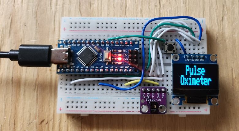
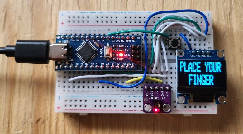
After uploading the code, the device is ready for testing. Immediately the OLED will display the “Pulse Oximeter” text.
Then it will display the message to place your finger.
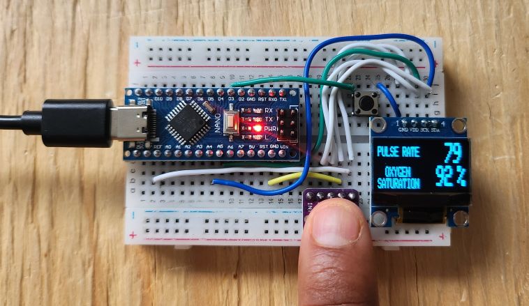
When you place the finger, it will start measuring the Pulse Rate in BPM and Oxygen Saturation in percentage.
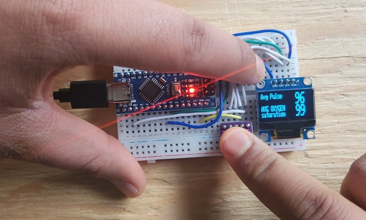
If you press the push button while placing the finger on MAX30102, the OLED will display the Average Pulse and Average Oxygen Saturation.
When no finger is placed on MAX30102 Sensor, the device goes to sleep mode and OLED will turn off in 5 seconds. The OLED will display the countdown timer as well.
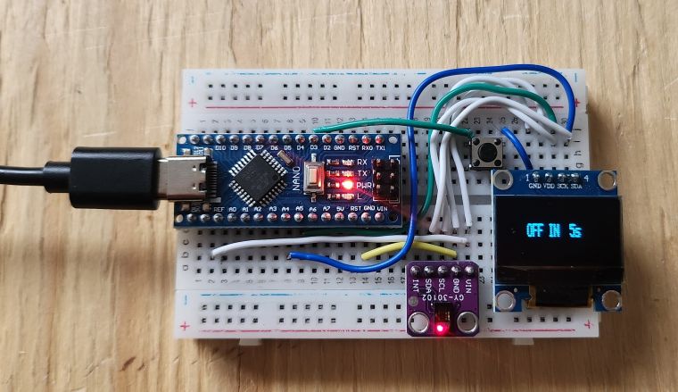
You can bring the OLED to working mode after pressing the push button again. This will wake up the device from sleep mode.
Thus, this is how you can make a portable pulse Oximeter using the Arduino, MAX30102 Sensor & display the Blood Oxygen and Heart Rate in OLED Display.

")


4 Comments
Why do you constantly mix references to the MAX30102 and the MAX30105 within your text here?
make code for ESP32 please
Is there a way to change the beat average?
Why doesn’t the monitor work and the sensor itself doesn’t light up? Only the Arduino board itself lights up? Although everything is fine with the code(