

Blood Oxygen & Heart Rate Monitor with MAX30100 Pulse Oximeter & Arduino
In this project we will make a device that can measure Blood Oxygen & Heart Rate using MAX30100 Pulse Oximeter & Arduino. The blood Oxygen Concentration termed as SpO2 is measured in Percentage and Heart Beat/Pulse Rate is measured in BPM. The MAX30100 is a Pulse Oximetry and heart rate monitor sensor solution. You can also use MAX30102 which is an upgraded version of MAX30100.
We will display the SpO2 and BPM value in 0.96″ OLED Display. With each beat, the display value is changed in the OLED screen. By using Bluetooth module HC-05/HC-06 (operating in a slave mode), we can send data to the android app wirelessly and monitor the data on the app as well as keep a track record of the data in text format. In this way, we can send the data read from the device to another device or to the Internet. This wearable device can be used by athletes to monitor their heart rate and blood oxygen levels during a workout.
You can also go through the basic & advanced version of this project:
1. Interfacing MAX30100 Pulse Oximeter Sensor with Arduino
2. MAX30100 Pulse Oximeter with ESP8266 on Blynk IoT App
Bill of Materials
Following are the components required for this project, i.e Blood Oxygen & Heart Rate Monitor with MAX30100 Pulse Oximeter & Arduino. All the components can be purchased from Amazon. The components name as well as purchased link is given below.
| S.N. | Components Name | Quantity | Purchase Links |
|---|---|---|---|
| 1 | Arduino Nano Board | 1 | Amazon | AliExpress |
| 2 | MAX30100 Pulse Oximeter Sensor | 1 | Amazon | AliExpress |
| 4 | 0.96" I2C OLED Display | 1 | Amazon | AliExpress |
| 5 | HC-05 Bluetooth Module | 1 | Amazon | AliExpress |
| 6 | Connecting Wires | 10 | Amazon | AliExpress |
| 7 | Breadboard | 1 | Amazon | AliExpress |
How does Pulse Oximeter Works?
Oxygen enters the lungs and then is passed on into blood. The blood carries oxygen to the various organs in our body. The main way oxygen is carried in our blood is by means of hemoglobin. During a pulse oximetry reading, a small clamp-like device is placed on a finger, earlobe, or toe.

Small beams of light pass through the blood in the finger, measuring the amount of oxygen. It does this by measuring changes in light absorption in oxygenated or deoxygenated blood.

MAX30100 Pulse Oximeter

The sensor is an integrated pulse oximetry and heart-rate monitor sensor solution. It combines two LED’s, a photo detector, optimized optics, and low-noise analog signal processing to detect pulse and heart-rate signals. It operates from 1.8V and 3.3V power supplies and can be powered down through software with negligible standby current, permitting the power supply to remain connected at all times.
Features
|
1 2 3 |
1. Consumes very low power (operates from 1.8V and 3.3V) 2. Ultra-Low Shutdown Current (0.7µA, typ) 3. Fast Data Output Capability |
Working of MAX30100 Pulse Oximeter and Heart-Rate Sensor
The device has two LEDs, one emitting red light, another emitting infrared light. For pulse rate, only the infrared light is needed. Both the red light and infrared light is used to measure oxygen levels in the blood.
When the heart pumps blood, there is an increase in oxygenated blood as a result of having more blood. As the heart relaxes, the volume of oxygenated blood also decreases. By knowing the time between the increase and decrease of oxygenated blood, the pulse rate is determined.
It turns out, oxygenated blood absorbs more infrared light and passes more red light while deoxygenated blood absorbs red light and passes more infrared light. This is the main function of the MAX30100: it reads the absorption levels for both light sources and stored them in a buffer that can be read via I2C.
Circuit Diagram & Connections
The circuit diagram & connection for interfacing MAX30100 Pulse Oximeter with Arduino along with HC-05 Bluetooth Module & OLED Display is given below.

MAX30100 & OLED Display works on I2C Communication Protocol. So its SDA & SCL pin is connected to I2C pin of Arduino, i.e A4 & A5. Similarly Bluetooth module is an UART module and need to be connected to Tx & Rx pins of Arduino.
PCB Designing for Portable Pulse Oximeter
The PCB for Portable Pulse Oximeter has been designed in EasyEDA online PCB making tool. Below is the front view and Back View of the PCB.

The Gerber File for the PCB is given below. You can simply download the Gerber File and order the PCB from ALLPCB at 1$ only.
PCB Ordering, Soldering & Mounting
You can use this Gerber file to order high quality PCB for this project. To do that visit the ALLPCB official website by clicking here: https://www.allpcb.com/.

You can now upload the Gerber File by choosing the Quote Now option. From these options, you can choose the Material Type, Dimensions, Quantity, Thickness, Solder Mask Color and other required parameters.

After filling all details, select your country and shipping method. Finally you can place the order.
So after a week I got the PCB from ALLPCB. The PCB quality is good and excellent.

After that you can solder all the necessary components as per circuit diagram and make the final product ready.

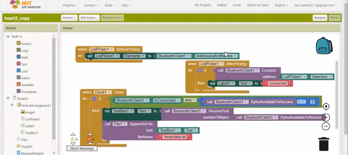
The Android App
The Pulse Rate and Blood Oxygen concentration that is displayed on OLED Display can be transferred wirelessly to Android device using Andorid App over a Bluetooth Connection.

This App has been designed using MIT App Inventor. The link for both the files, i.e APK files and .aia files is given below. You can edit modify the Android app on MIT App inventor after importing .aia file. The app can be installed on any Android device and can be connected to HC-05 Bluetooth Module.
Download Android App: Download
Download .aia File: Download
Source Code/Program
The source Code/program for interfacing MAX30100 Pulse Oximter and Heart Rate Sensor with Arduino is given below. Copy this code and upload it to Arduino Board.
The library files can be downloaded from here:
1. Arduino MAX30100 Library
2. OkaOLED Library
3. Adafruit GFX Library
|
1 2 3 4 5 6 7 8 9 10 11 12 13 14 15 16 17 18 19 20 21 22 23 24 25 26 27 28 29 30 31 32 33 34 35 36 37 38 39 40 41 42 43 44 45 46 47 48 49 50 51 52 53 54 55 56 57 58 59 60 61 62 63 64 65 66 67 68 69 70 71 72 73 74 75 76 77 78 79 80 81 82 83 84 85 86 87 88 89 90 91 92 93 94 95 96 97 98 99 100 101 |
#include <Wire.h> #include "MAX30100_PulseOximeter.h" #include "Wire.h" #include "Adafruit_GFX.h" #include "OakOLED.h" #define REPORTING_PERIOD_MS 1000 OakOLED oled; PulseOximeter pox; uint32_t tsLastReport = 0; const unsigned char bitmap [] PROGMEM= { 0x00, 0x00, 0x00, 0x00, 0x01, 0x80, 0x18, 0x00, 0x0f, 0xe0, 0x7f, 0x00, 0x3f, 0xf9, 0xff, 0xc0, 0x7f, 0xf9, 0xff, 0xc0, 0x7f, 0xff, 0xff, 0xe0, 0x7f, 0xff, 0xff, 0xe0, 0xff, 0xff, 0xff, 0xf0, 0xff, 0xf7, 0xff, 0xf0, 0xff, 0xe7, 0xff, 0xf0, 0xff, 0xe7, 0xff, 0xf0, 0x7f, 0xdb, 0xff, 0xe0, 0x7f, 0x9b, 0xff, 0xe0, 0x00, 0x3b, 0xc0, 0x00, 0x3f, 0xf9, 0x9f, 0xc0, 0x3f, 0xfd, 0xbf, 0xc0, 0x1f, 0xfd, 0xbf, 0x80, 0x0f, 0xfd, 0x7f, 0x00, 0x07, 0xfe, 0x7e, 0x00, 0x03, 0xfe, 0xfc, 0x00, 0x01, 0xff, 0xf8, 0x00, 0x00, 0xff, 0xf0, 0x00, 0x00, 0x7f, 0xe0, 0x00, 0x00, 0x3f, 0xc0, 0x00, 0x00, 0x0f, 0x00, 0x00, 0x00, 0x06, 0x00, 0x00, 0x00, 0x00, 0x00, 0x00, 0x00, 0x00, 0x00, 0x00 }; void onBeatDetected() { Serial.println("Beat!"); oled.drawBitmap( 60, 20, bitmap, 28, 28, 1); oled.display(); } void setup() { Serial.begin(9600); oled.begin(); oled.clearDisplay(); oled.setTextSize(1); oled.setTextColor(1); oled.setCursor(0, 0); oled.println("Initializing pulse oximeter.."); oled.display(); Serial.print("Initializing pulse oximeter.."); if (!pox.begin()) { Serial.println("FAILED"); oled.clearDisplay(); oled.setTextSize(1); oled.setTextColor(1); oled.setCursor(0, 0); oled.println("FAILED"); oled.display(); for(;;); } else { oled.clearDisplay(); oled.setTextSize(1); oled.setTextColor(1); oled.setCursor(0, 0); oled.println("SUCCESS"); oled.display(); Serial.println("SUCCESS"); } pox.setOnBeatDetectedCallback(onBeatDetected); } void loop() { pox.update(); if (millis() - tsLastReport > REPORTING_PERIOD_MS) { Serial.print("Heart BPM:"); Serial.print(pox.getHeartRate()); Serial.print("-----"); Serial.print("Oxygen Percent:"); Serial.print(pox.getSpO2()); Serial.println("\n"); oled.clearDisplay(); oled.setTextSize(1); oled.setTextColor(1); oled.setCursor(0,16); oled.println(pox.getHeartRate()); oled.setTextSize(1); oled.setTextColor(1); oled.setCursor(0, 0); oled.println("Heart BPM"); oled.setTextSize(1); oled.setTextColor(1); oled.setCursor(0, 30); oled.println("Spo2"); oled.setTextSize(1); oled.setTextColor(1); oled.setCursor(0,45); oled.println(pox.getSpO2()); oled.display(); tsLastReport = millis(); } } |
MAX30100 Arduino Working Project
The project is tested both on the breadboard as well as in PCB Assembled board. Initially, when no finger is placed over MAX30100, the SPO2 & BPM value both are zero. When the finger is placed, the BPM & SPO2 values start appearing. But the value shown is not correct initially, then after a few seconds, the OLED Display starts showing the correct value.
Here is a working demonstration of the device working when assembled on breadboard.

Similarly the same thing is with the PCB portable device it also works super fine and we got the same results.

MAX30100 Not Working Troubleshooting
If you purchased the MAX30100 Module shown below, then it might not work as it has a serious design problem. The MAX30100 IC uses 1.8V for VDD and this particular module uses two regulators to achieve this voltage. Nothing wrong with that. However, if you look closely, the SCL and SDA pins are pulled-up via the 4.7k ohm resistors to 1.8V! This means it won’t work well with microcontrollers with higher logic levels.
1st Method
The solution is to remove the resistors from the board (encircled on the image below) and attach external 4.7k ohms resistors to SDA, SCL and INT Pin instead.

After removing all 4.7K Resistor, connect the INT, SDA, SCL pin to the external 4.7K Pull up resistor as shown in the image below.

2nd Method
Similarly you can use the second method to fix this issue if you don’t like the first one. It is enough to cut the path in the place of the red cross and make a jumper as shown by the yellow line. The jumper does not need an insulated wire. You can take a tinned strand from the stranded wire. The board is covered with a protective mask and there is no short circuit to the copper pour.

Video Demonstration & Explanation


")


39 Comments
good tutorial can you describe how to fix max 30100 resister
error help
Arduino: 1.8.10 (Windows 10), Board: “Arduino/Genuino Uno”
Sketch uses 15040 bytes (46%) of program storage space. Maximum is 32256 bytes.
Global variables use 1834 bytes (89%) of dynamic memory, leaving 214 bytes for local variables. Maximum is 2048 bytes.
Low memory available, stability problems may occur.
avrdude: stk500_getsync() attempt 1 of 10: not in sync: resp=0x45
avrdude: stk500_getsync() attempt 2 of 10: not in sync: resp=0xfc
avrdude: stk500_getsync() attempt 3 of 10: not in sync: resp=0x45
avrdude: stk500_getsync() attempt 4 of 10: not in sync: resp=0x7c
avrdude: stk500_getsync() attempt 5 of 10: not in sync: resp=0x11
avrdude: stk500_getsync() attempt 6 of 10: not in sync: resp=0xfc
avrdude: stk500_getsync() attempt 7 of 10: not in sync: resp=0x45
avrdude: stk500_getsync() attempt 8 of 10: not in sync: resp=0x1c
avrdude: stk500_getsync() attempt 9 of 10: not in sync: resp=0x11
avrdude: stk500_getsync() attempt 10 of 10: not in sync: resp=0x3c
An error occurred while uploading the sketch
This report would have more information with
“Show verbose output during compilation”
option enabled in File -> Preferences.
Please help me, I have the MAX 30102 sensor and with this code it doesn’t work correctly. What changes I have to do?
there is a problem with code and same tings with sensor when i am trying to just test the Max 30100 tell you this error Not used: C:\Users\User\Documents\Arduino\libraries\MAX30100lib
exit status 1
Error compiling for board Arduino Uno.
hi If i was to do this with the Arduino Nano 33 BLE
how would i alter code
Arduino: 1.8.10 (Windows 10), Board: “Arduino Nano, ATmega328P”
Sketch uses 15052 bytes (48%) of program storage space. Maximum is 30720 bytes.
Global variables use 1846 bytes (90%) of dynamic memory, leaving 202 bytes for local variables. Maximum is 2048 bytes.
Low memory available, stability problems may occur.
avrdude: loadaddr(): (b) protocol error, expect=0x14, resp=0xfc
avrdude: loadaddr(): (b) protocol error, expect=0x14, resp=0xfc
avrdude: loadaddr(): (b) protocol error, expect=0x14, resp=0xfc
avrdude: stk500_paged_load(): (a) protocol error, expect=0x10, resp=0x00
avrdude: stk500_cmd(): programmer is out of sync
avr_read(): error reading address 0x0000
read operation not supported for memory “flash”
avrdude: failed to read all of flash memory, rc=-2
avrdude: stk500_disable(): protocol error, expect=0x14, resp=0x00
avrdude: stk500_disable(): protocol error, expect=0x14, resp=0x00
This report would have more information with
“Show verbose output during compilation”
option enabled in File -> Preferences.
Everything working fine till I add update pox command.
When I add this command in loop function it gets off.
What is the problem.
I m new and lerner .
Using 6 pin oled disply to see result.
I have used cut connection and add wire method, still not working but when I connect INT TO GND after initialising command senser glows and shows result on COM port i.e serial port.
Where is the code for bluetooth module
There is another post for bluetooth part. Check the link in yt video description website article.
Hello Mr. Alam. i can’t find another post for bluetooth part.
Hallo Mr. Alam,
I use the green oxygen-modul MAX30100 with 5V. SDA -> A4 SCL -> A5 . I use arduino nano.
Compiling and upload is ok. No error.
My problem is in
setup void {
if (!pox.begin()) {
Serial.println(“FAILED”);
……..} }
I cannot initialize the pox. On Oled is written “failed”.
Who can help me?
The MAX30100 Sensor is damaged. Please fix the sensor first. The method of fixing the sensor is given.
I´m waiting for answer to fix my project soon.
Do I have the same problems with the red GY-MAX30100
Thanks. Do I have the same problems with the red GY-MAX30100
There is a method to fix the issue.
You can try if its not working.
Hello,
I have removed all 4.7K Resistor from the sensor MAX30100/30102 (1st Method) and connect the INT, SDA, SCL pin to the external 4.7K Pull up resistor and INT to D2 as shown in the image.
My question: must I connect with 3,3V or 5V? In the discription of the sensor I read it works with 3,3V.
My problem is: compiling and upload ok but sensor error “INIT FAILED”.
How can I fix this problem?
Can I send you pictures?
On Pinterest I send you a picture of wiring the sensor MAX30100/30102 with the extern resistors (1st method).
Maybe you can help me fixing my problems with init the sensor. I like to use the blood oxygen and heart rate monitor with my friends. They are still waiting.
I´m still waiting for answer to fix my problems.
I don´t think it´s good if you offer a forum and don´t respond.
Hey bro, the first and 2nd method both works fine, there is no problem. If it’s not working even after trying the 1st and 2nd method. Then maybe your sensor is damaged. Buy the purple color sensor, not the green one. The purple color sensor doesn’t have any issue.
Hey bro, the first and 2nd method both works fine, there is no problem. If it’s not working even after trying the 1st and 2nd method. Then maybe your sensor is damaged. Buy the purple color sensor, not the green one. The purple color sensor doesn’t have any issues.
Thank you for answer.
Now I use:
Arduino UNO, LCD (5V) and purple GY-Max30100 sensor (3,3V).
Compiling ok
Upload OK
Init succeed
Data realistic with finger on sensor.
Problem: When I take off the finger, the data do not go back to zero. Only when I put a dark plastic (packaging of sensor) over the sensor, the data are going back to zero.
Is this normal?
This day i Test the second version of this project. Using arduino NANO and OLED display.
It is strange!! This project only works when I put a dark plastic (packaging of the sensor) between my finger and the sensor. Then I get right data for O² and heart rate. When I put my finger directly on the sensor, the data are zero.
Strange!!
Do you understand this? Can you help me?
hi, even i am facing same problem,
did u resolved it?
No, I+m still waiting for answer/help.
Since on Week I´m waiting for an answer to fix my problems. I´m not glad about this service. Maybe it is my first and my last project on this plattform. I think you can´t understand how somebody feels waiting for help and get no answer.
Sir , is it needed to cut and short the connections on MAX30100 arduino module , arduino nano ?????
I only use the purple GY-Max30100 sensor. I have removed all 4.7K Resistor from the sensor MAX30100/30102 (1st Method) and connect the INT, SDA, SCL pin to the external 4.7K Pull up resistor and INT to D2 as shown in the image.
The green sensor doen´t work.
But the purple GY-Max30100 sensor work well.
Hey great work ! Thanks. I am wondering what is the signs just below the blinking heart logo. I scan the codes and couldnt find anything related. Appreciated!
Just show me one example that indian making one thing correct???!!! they are just talking taking taking
I need max3010x code for “CCS C” compiler. I want to do this work on pic (eg 18f4550). Can you help me?
can I contact you on email. I need total solution of these project. can you help me professionally ? my email id is
[email protected]
can u plz tell is the sensors used in this project are also used to measure glucose level?
Hello creator , i have a doubt ; how did you created the circuit diagram using arduino and MAX30100 sensor .I just want to know which stimulator you have used to make the circuit. please replay me the online website of the stimulator.
use fritzing to draw diagrams. download fritzing from fritzing.org
I am using the purple sensor still intitialization failed please help
Good Morning,
As I am preparing myself to implement this,
Is the administrator still available?
hello in app instead spo2 and bpm is written ” Hint for TextBox1″ what i need to do ?