

Overview
In this tutorial, we will learn Interfacing of LoRa Module SX1276 with STM32 Bluepill Microcontroller. The LR1276UA-A-915 module uses SX1276 IC and works on a 915MHz frequency. Using the Frequency hopping, it gives the sweet balance of quality signal transmission will cover a range of 915MHz. The LoRa LR1276/SX1276 works with SPI communication protocol so it can be used with any microcontroller that supports SPI. The SX1276 or LR1276 module can be easily interfaced with the STM32F103 chip.
Earlier we used Reyax LoRa module RYLR890/RYLR896 with Arduino. You can go through the post as well. The Reyax RYLR890 LoRa module works on UART Communication and has some communication breakage while testing. But Gplus-IoT LR1276 is an SPI Module with better performance similar to LoRa SX1278 Module.
The tutorial consists of two examples. In the first example, we will send a simple “Hello World” message from LoRa Sender/Transmitter to Receiver. But in the second example, we will send the sensor data wirelessly. The DHT11 Humidity Temperature sensor is best suited for the testing application. The STM32 LoRa Sender will send the sensor data to the STM32 LoRa Receiver.
Bill of Materials
All the components required for this tutorial are given below along with the purchase link.
| S.N. | Components Name | Quantity | Purchase Links |
|---|---|---|---|
| 1 | STM32 Microcontroller | 2 | Amazon | AliExpress |
| 2 | LoRa Module LR1276/SX1276 | 2 | Gplus-IoT on TECHDesign |
| 3 | DHT11 Sensor | 1 | Amazon | AliExpress |
| 4 | 3.7V Lithium-Battery | 2 | Amazon | AliExpress |
| 5 | 0.96" I2C OLED Display | 1 | Amazon | AliExpress |
| 6 | Connecting Wires | 20 | Amazon | AliExpress |
| 7 | Breadboard | 1 | Amazon | AliExpress |
LoRa Module LR1276/SX1276
The LR1276 module is designed based on SX1276. The SX1276 incorporates the LoRa spread spectrum modem which is capable of achieving a significantly longer range than existing systems based on FSK or OOK modulation. At maximum data rates of LoRa, the sensitivity is 8dB better than FSK. But using a low-cost bill of materials with a 2Oppm XTAL LoRa can improve receiver sensitivity by more than 20dB compared to FSK.

LoRa also provides significant advances in selectivity and blocking performance, further improving communication reliability. For maximum flexibility the user may decide on the spread spectrum modulation bandwidth (BW), spreading factor (SF), and error correction rate (CR). Another benefit of the spread modulation is that each spreading factor is orthogonal. It means multiple transmitted signals can occupy the same channel without interfering.
This also permits simple coexistence with existing FSK-based systems. Standard GFSK, FSK, 00K, and GMSK modulation is also provided to allow compatibility with existing systems or standards such as wireless MBUS and IEEE 802.15.4g.
LR1276/SX1276 Features
- LoRa Modem
- 168 dB maximum link budget
- +20 dBm – 100 mW constant RF output vs. V supply
- +14 dBm high efficiency PA
- Programmable bit rate up to 300 kbps
- High sensitivity: down to -148 dBm
- Bullet-proof front end: IIP3 = -11 dBm
- Excellent blocking immunity
- Operating Voltage 1.8-3.7V
- Low RX current of 9.9 mA, 200 nA register retention
- Fully integrated synthesizer with a resolution of 61 Hz
- FSK, GFSK, MSK, GMSK, LoRaTMand 00K modulation
- Built-in bit synchronizer for clock recovery
- Preamble detection
- 127 dB Dynamic Range RSSI
- Automatic RF Sense and CAD with ultra-fast AFC
- Packet engine up to 256 bytes with CRC
- Built-in temperature sensor and low battery indicator
Applications
- Automated Meter Reading.
- Home and Building Automation.
- Wireless Alarm and Security Systems.
- Industrial Monitoring and Control
- Long-range Irrigation System
LR1276/SX1276 Pinout
The Gplus-IoT LoRa Module LR1276 has total 18 pins which functionalities are as follows:

Designing LR1276 Breakout Board
The Gplus-IoT LR1276 chip is very tiny in size so its very difficult to interface it with any controller. So I designed a small breakout board using EasyEDA software and converted it into a PCB. The PCB layout looks something like this.

The Gerber File for the PCB is given below. You can simply download the Gerber File and order the PCB from ALLPCB at 1$ only.
You can use this Gerber file to order high quality PCB for this project. To do that visit the ALLPCB official website by clicking here: https://www.allpcb.com/.

You can now upload the Gerber File by choosing the Quote Now option. From these options, you can choose the Material Type, Dimensions, Quantity, Thickness, Solder Mask Color and other required parameters.

After filling all details, select your country and shipping method. Finally you can place the order.

Then I soldered the LR1276 chip into the PCB. The SX1276 chip has a very small gap between the two consecutive pins. So it requires good soldering skills for soldering the components.

LoRa Library for STM32
The Arduino LoRa Library is not supported by STM32F103 Board. That is why there is a modified library for STM32F103 Board for Arduino IDE. The STM32 LoRa library is used for sending and receiving data using LoRa radios.
This library exposes the LoRa radio directly and allows you to send data to any radios in range with the same radio parameters. All data is broadcasted and there is no addressing.
Interfacing Gplus-IoT LoRa LR1276/SX1276 with STM32
Schematic & Connection
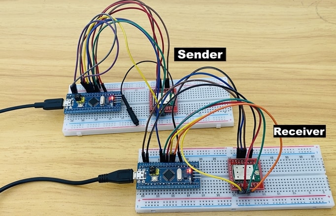
Now let us interface LoRa Module LR1276/SX1276 with STM32F103C Board and make a simple STM32 LoRa Sender Receiver Device. The connection between SX1276 & STM32F103 is as follows:
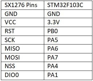
The schematic is given below. You can assemble the pair of circuits on the breadboard. One of the circuits will act as a transmitter or sender and the other as a receiver.
Sender Code
|
1 2 3 4 5 6 7 8 9 10 11 12 13 14 15 16 17 18 19 20 21 22 23 24 25 26 27 28 29 30 31 32 33 34 35 36 37 38 39 40 41 42 43 44 45 |
#include <SPI.h> #include <LoRa_STM32.h> #define SS PA4 #define RST PB0 #define DI0 PA1 #define TX_P 17 #define BAND 915E6 #define ENCRYPT 0x78 int counter = 0; void setup() { Serial.begin(115200); while (!Serial); Serial.println("LoRa Sender"); LoRa.setTxPower(TX_P); LoRa.setSyncWord(ENCRYPT); LoRa.setPins(SS, RST, DI0); if (!LoRa.begin(BAND)) { Serial.println("Starting LoRa failed!"); while (1); } } void loop() { Serial.print("Sending packet: "); Serial.println(counter); // send packet LoRa.beginPacket(); LoRa.print("hello "); LoRa.print(counter); LoRa.endPacket(); counter++; delay(5000); } |
Receiver Code
|
1 2 3 4 5 6 7 8 9 10 11 12 13 14 15 16 17 18 19 20 21 22 23 24 25 26 27 28 29 30 31 32 33 34 35 36 37 38 39 40 41 42 43 44 45 |
#include <SPI.h> #include <LoRa_STM32.h> #define SS PA4 #define RST PB0 #define DI0 PA1 #define TX_P 17 #define BAND 915E6 #define ENCRYPT 0x78 void setup() { Serial.begin(115200); while (!Serial); Serial.println("LoRa Receiver"); LoRa.setTxPower(TX_P); LoRa.setSyncWord(ENCRYPT); LoRa.setPins(SS, RST, DI0); if (!LoRa.begin(BAND)) { Serial.println("Starting LoRa failed!"); while (1); } } void loop() { // try to parse packet int packetSize = LoRa.parsePacket(); if (packetSize) { // received a packet Serial.print("Received packet '"); // read packet while (LoRa.available()) { Serial.print((char)LoRa.read()); } // print RSSI of packet Serial.print("' with RSSI "); Serial.println(LoRa.packetRssi()); } } |
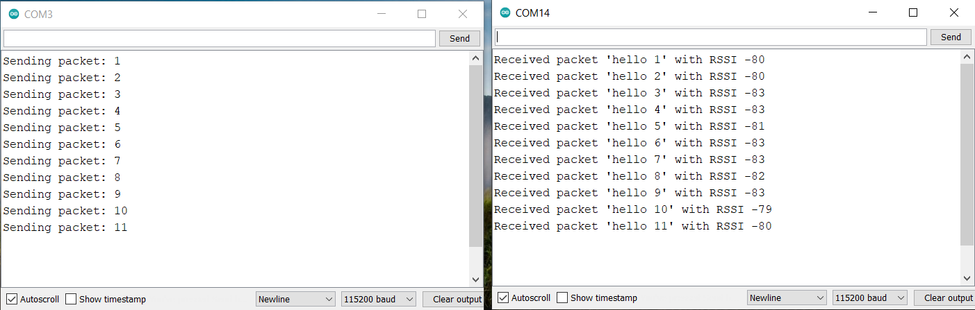
Testing & Result
Once code is uploaded, open the Serial Monitor for both transmitter and receiver. The sender will send some data which is received by receiver.
Sending Sensor Data Wirelessly using LoRa Module
Schematic & Connection
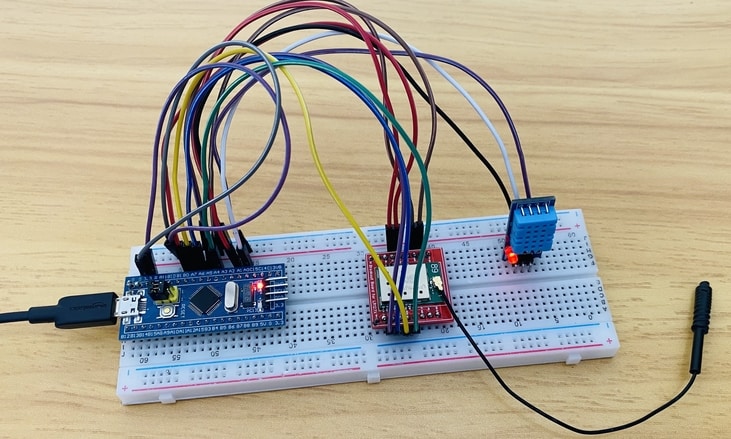
Let us go through the second example now. In this example, we will be Interfacing SX1276 with STM32 and DHT11 sensor to the Sender Circuit. The DHT11 is a basic, ultra low-cost digital temperature and humidity sensor. It uses a capacitive humidity sensor and a thermistor to measure the surrounding air and spits out a digital signal on the data pin.
The Sensor works don’t require an analog connection, rather if it is connected to a digital pin, it will give an output. We will send the DHT11 Sensor reading wirelessly from STM32 LoRa Sender to STM32 LoRa Receiver.

On the receiver part, we added a 0.96″ I2C OLED Display to the circuit. Connect the VCC & GND pin of OLED to STM32 3.3V & GND Pins respectively. Then connect the SDA & SCL Pins of OLED to PB7 & PB6 of OLED respectively.
Check the previous similar project here: Send Sensor Data Wirelessly using LoRa & Arduino
The LoRa LR1276/SX1276 STM32 Sender and Receiver Code is given below. The Sender & receiver Code requires the following libraries. Download all these libraries and add them through the library manager.
1. DHT11 Library: https://github.com/adafruit/DHT-sensor-library
2. Adafruit GFX Library: https://github.com/adafruit/Adafruit-GFX-Library
3. Adafruit SSD1306 Library: https://github.com/adafruit/Adafruit_SSD1306
Sender Code
|
1 2 3 4 5 6 7 8 9 10 11 12 13 14 15 16 17 18 19 20 21 22 23 24 25 26 27 28 29 30 31 32 33 34 35 36 37 38 39 40 41 42 43 44 45 46 47 48 49 50 51 52 53 54 55 56 57 58 59 60 61 62 63 64 65 66 67 68 69 |
#include <SPI.h> #include <LoRa_STM32.h> #include<DHT.h> //Library for using DHT sensor #define DHTPIN PA0 #define DHTTYPE DHT11 #define NSS PA4 #define RST PB0 #define DI0 PA1 #define TX_P 17 #define BAND 915E6 #define ENCRYPT 0x78 int counter = 0; String LoRaMessage = ""; DHT dht(DHTPIN, DHTTYPE); void setup() { Serial.begin(115200); while (!Serial); Serial.println(F("LoRa Sender")); //LoRa.setTxPower(TX_P); LoRa.setSyncWord(ENCRYPT); LoRa.setPins(NSS, RST, DI0); if (!LoRa.begin(BAND)) { Serial.println(F("Starting LoRa failed!")); while (1); } dht.begin(); } void loop() { float humidity = dht.readHumidity(); //Gets Humidity value float temperature = dht.readTemperature(); //Gets Temperature value Serial.print(F("Sending packet: ")); Serial.println(counter); Serial.print(F("Temperature: ")); Serial.print(temperature); Serial.println(F("*C")); Serial.print(F("Humidity: ")); Serial.print(humidity); Serial.println(F("%")); Serial.println(); LoRaMessage = String(counter) + "/" + String(temperature) + "&" + String(humidity); // send packet LoRa.beginPacket(); LoRa.print(LoRaMessage); LoRa.endPacket(); counter++; delay(3000); } |
Receiver Code
|
1 2 3 4 5 6 7 8 9 10 11 12 13 14 15 16 17 18 19 20 21 22 23 24 25 26 27 28 29 30 31 32 33 34 35 36 37 38 39 40 41 42 43 44 45 46 47 48 49 50 51 52 53 54 55 56 57 58 59 60 61 62 63 64 65 66 67 68 69 70 71 72 73 74 75 76 77 78 79 80 81 82 83 84 85 86 87 88 89 90 91 92 93 94 95 96 97 98 99 100 101 102 103 104 105 |
#include <SPI.h> #include <Wire.h> #include <Adafruit_GFX.h> #include <Adafruit_SSD1306.h> #include <LoRa_STM32.h> #define SCREEN_WIDTH 128 // OLED display width, in pixels #define SCREEN_HEIGHT 64 // OLED display height, in pixels #define OLED_RESET -1 // Reset pin # (or -1 if sharing reset pin) Adafruit_SSD1306 display(SCREEN_WIDTH, SCREEN_HEIGHT, &Wire, OLED_RESET); #define SS PA4 #define RST PB0 #define DI0 PA1 #define TX_P 17 #define BAND 915E6 #define ENCRYPT 0x78 String counter; String temperature; String humidity; void setup() { Serial.begin(115200); while (!Serial); Serial.println("LoRa Receiver"); //LoRa.setTxPower(TX_P); LoRa.setSyncWord(ENCRYPT); LoRa.setPins(SS, RST, DI0); if (!LoRa.begin(BAND)) { Serial.println("Starting LoRa failed!"); while (1); } if (!display.begin(SSD1306_SWITCHCAPVCC, 0x3C)) { Serial.println(F("SSD1306 allocation failed")); for (;;); // Don't proceed, loop forever } } void loop() { // try to parse packet int pos1, pos2; int packetSize = LoRa.parsePacket(); if (packetSize) { // received a packet Serial.print("Received packet: "); String LoRaData = LoRa.readString(); Serial.print(LoRaData); // read packet while (LoRa.available()) { Serial.print((char)LoRa.read()); } // print RSSI of packet Serial.print("' with RSSI "); Serial.println(LoRa.packetRssi()); pos1 = LoRaData.indexOf('/'); pos2 = LoRaData.indexOf('&'); counter = LoRaData.substring(0, pos1); temperature = LoRaData.substring(pos1 + 1, pos2); humidity = LoRaData.substring(pos2 + 1, LoRaData.length()); Serial.print(F("Packet No. = ")); Serial.println(counter); Serial.print(F("Temperature = ")); Serial.print(temperature); Serial.println(F("*C")); Serial.print(F("Humidity = ")); Serial.print(humidity); Serial.println(F("%")); Serial.println(); display.clearDisplay(); display.setTextColor(WHITE); display.setTextSize(2); display.setCursor(0, 10); display.print("T: "); display.print(temperature); display.print("*C"); display.setTextSize(2); display.setCursor(0, 40); display.print("H: "); display.print(humidity); display.print("%"); display.display(); delay(500); } } |
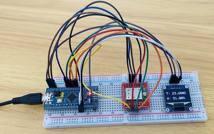
Testing & Results
After uploading the code on both the sender and receiver circuit, the LoRa sender will start. It means the sender circuit will read the humidity temperature data from DHT11 Sensor and send it wirelessly.
On the receiver side, the LoRa will receive data wirelessly. The received data will be displayed on OLED Display. The temperature and humidity value gets updated whenever the data packet is received.
This is how you can make a point-to-point communication between two Gplus-IoT LR1276 or Generic SX1276 LoRa Module with the help of an STM32F103C microcontroller.
A dedicated plug and play type LoRa USB Dongle is also available for learning more about two way LoRa Communication.
Video Tutorial & Guide


1 Comment
Lora module link is dead. Where should we buy one today?