

Overview
In this tutorial, we will learn Interfacing of LoRa Module SX1278 with STM32 Bluepill Microcontroller. The Ra-02 module uses SX1278 IC and works on a 433MHz frequency. Using the Frequency hopping, it gives the sweet balance of quality signal transmission—will cover a range of 420-450MHz. The LoRa SX1278 works with SPI communication protocol so it can be used with any microcontroller that supports SPI. The SX1278 module can be easily interfaced with the STM32F103 chip.
The tutorial consists of two examples. In the first example, we will send a simple “Hello World” message from LoRa Sender/Transmitter to Receiver. But in the second example, we will send the sensor data wirelessly. The BME280 Barometric Pressure Sensor gives the information of Barometric Pressure, Temperature, Humidity & Approx. Altitude. The STM32 LoRa Sender will send the sensor data to the STM32 LoRa Receiver.
If you are reading this post from the North America region, then you can work with 915MHz LoRa Module SX1276.
Bill of Materials
All the components required for this tutorial are given below along with the purchase link.
| S.N. | Components Name | Quantity | Purchase Links |
|---|---|---|---|
| 1 | STM32F103C Microcontroller | 2 | Amazon | AliExpress |
| 2 | LoRa Module SX1278 | 2 | Amazon | AliExpress |
| 3 | BME280 Sensor | 1 | Amazon | AliExpress |
| 4 | 5V Power Supply | 2 | Amazon | AliExpress |
| 5 | Connecting Jumper Wires | 20 | Amazon | AliExpress |
| 6 | Breadboard | 1 | Amazon | AliExpress |
LoRa Module SX1278
The SX1278 Ra-02 Chip is manufactured by Semtech. The SX1278 RF module is mainly used for long-range spread spectrum communication. It can resist Minimize current consumption & has a high sensitivity of -148 dBm with a power output of +20 dBm. A long transmission distance with almost 5km can be achieved with high reliability. Thus SX1278 is great for IoT applications to send sensor data to the cloud over long ranges.

This module uses SX1278 IC from SEMTECH and works on a 433MHz frequency. Frequency hopping—which gives you that sweet balance of quality signal transmission will cover a range of 420-450 MHz. This long-range wireless capability is packed into a small (17 x 16mm) package and delivered without an antenna.
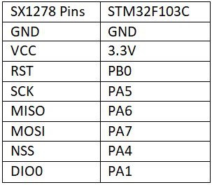
SX1278 Pinout

Pin 1: ANT – This pin is to attach to the antenna.
Pin 2, 9, 16: GND – Ground pin of common ground with power supply and controllers.
Pin 3: 3.3V – To power up the device pin 3 will help for power input.
Pin 4: RESET – Pin 4 is to reset the module through an external signal.
Pin 5, 6, 7, 8, 10, 11: DIO0, DIO1, DIO2, DIO3, DIO4, DIO5 – To perform the general, I/O function through module the DIO pins will help. These pins is customizable as an interrupt pin.
Pin 12: SCK – SCK pin is for the clock pulse during the SPI communication.
Pin 13: MISO – MISO means Master in and Slave out that transfers data transfer from the Module to the Controller. The Master is a controller & SX1278 is Slave.
Pin 14: MOSI – MOSI means Master out Slave In. So, this pin will receive the data from Controller.
Pin 15: NSS – NSS is a chip select/enable pin will help to activate the slave.
LoRa Frequency Allocation
LoRa frequency is not legal everywhere. I am from India and here the unlicensed Frequency range is from 865MHz to 867MHz. So I am only allowed to use this frequency range. The SX1278 has a frequency of 433MHz so I am not allowed to use it for an extended time aside from for an academic purpose. Similarly, check the allowed Ranges in your country and confirm you’re allowed to use the actual frequency range. LoRa modules do are available different frequency ranges, the foremost common being the 433MHz, 915MHz, and 868MHz.
Interfacing LoRa SX1278 with STM32
Now let us interface LoRa Module SX1278 with STM32F103C Board and make a simple STM32 LoRa Sender Receiver Device. The connection between SX1278 & STM32F103 is as follows:
The schematic is given below. You can assemble the pair of the circuit on the breadboard. One of the circuits will act as a transmitter or sender and the other as a receiver.

LoRa Library for STM32
The Arduino LoRa Library is not supported by STM32F103 Board. That is why there is a modified library for STM32F103 Board for Arduino IDE. The STM32 LoRa library is used for sending and receiving data using LoRa radios.
This library exposes the LoRa radio directly and allows you to send data to any radios in range with the same radio parameters. All data is broadcasted and there is no addressing.
Sender & Receiver Code

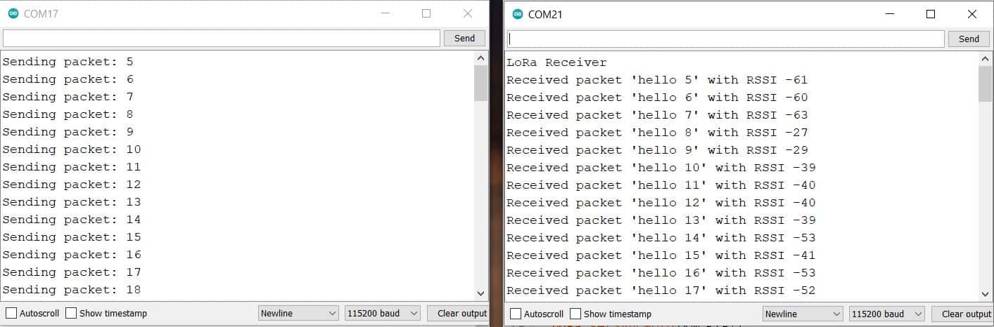
Sender Code
|
1 2 3 4 5 6 7 8 9 10 11 12 13 14 15 16 17 18 19 20 21 22 23 24 25 26 27 28 29 30 31 32 33 34 35 36 37 38 39 40 41 42 43 44 |
#include <SPI.h> #include <LoRa_STM32.h> #define SS PA4 #define RST PB0 #define DI0 PA1 #define TX_P 17 #define BAND 433E6 #define ENCRYPT 0x78 int counter = 0; void setup() { Serial.begin(115200); while (!Serial); Serial.println("LoRa Sender"); LoRa.setTxPower(TX_P); LoRa.setSyncWord(ENCRYPT); LoRa.setPins(SS, RST, DI0); if (!LoRa.begin(BAND)) { Serial.println("Starting LoRa failed!"); while (1); } } void loop() { Serial.print("Sending packet: "); Serial.println(counter); // send packet LoRa.beginPacket(); LoRa.print("hello "); LoRa.print(counter); LoRa.endPacket(); counter++; delay(5000); } |
Receiver Code
|
1 2 3 4 5 6 7 8 9 10 11 12 13 14 15 16 17 18 19 20 21 22 23 24 25 26 27 28 29 30 31 32 33 34 35 36 37 38 39 40 41 42 43 44 45 |
#include <SPI.h> #include <LoRa_STM32.h> #define SS PA4 #define RST PB0 #define DI0 PA1 #define TX_P 17 #define BAND 433E6 #define ENCRYPT 0x78 void setup() { Serial.begin(115200); while (!Serial); Serial.println("LoRa Receiver"); LoRa.setTxPower(TX_P); LoRa.setSyncWord(ENCRYPT); LoRa.setPins(SS, RST, DI0); if (!LoRa.begin(BAND)) { Serial.println("Starting LoRa failed!"); while (1); } } void loop() { // try to parse packet int packetSize = LoRa.parsePacket(); if (packetSize) { // received a packet Serial.print("Received packet '"); // read packet while (LoRa.available()) { Serial.print((char)LoRa.read()); } // print RSSI of packet Serial.print("' with RSSI "); Serial.println(LoRa.packetRssi()); } } |
Result
Sending Sensor Data Wirelessly using LoRa Module
Let us go through the second example now. In this example, we will be Interfacing SX1278 with STM32 and BME280 sensor to the Sender Circuit. The BME280 is an integrated environmental sensor developed specifically for mobile applications that have high linearity & accuracy for pressure, humidity and temperature measurements.

The Sensor works on I2C Protocol so its I2C Pins, i.e SDA & SCL is connected to PB7 & PB6 respectively. We will send the BME280 Sensor reading wirelessly from STM32 LoRa Sender to STM32 LoRa Receiver.
Check the previous similar project here: Send Sensor Data Wirelessly using LoRa & Arduino
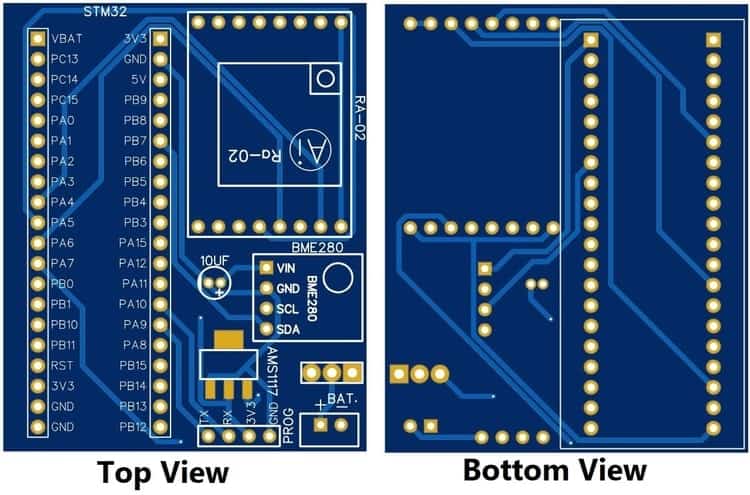
Project PCB Gerber File & PCB Ordering Online
If you don’t want to assemble the circuit on breadboard and you want PCB for the project, then here is the PCB for you. The PCB Board for the STM32 LoRa SX1278 Sender & Receiver is designed using EasyEDA online Circuit Schematics & PCB designing tool. The image of the Sender PCB is given below.
Similarly the image of the Receiver PCB is given below.
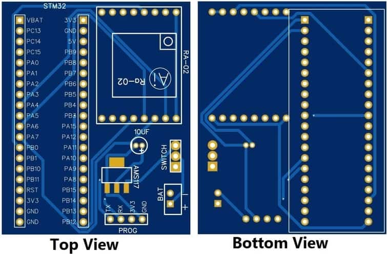
The Gerber File for the PCB is given below. You can simply download the Gerber File and order the PCB from ALLPCB at 1$ only.
- Download Gerber File for Sender PCB: Sender PCB
- Download Gerber File for Receiver PCB: Receiver PCB
You can use this Gerber file to order high quality PCB for this project. To do that visit the ALLPCB official website by clicking here: https://www.allpcb.com/.

You can now upload the Gerber File by choosing the Quote Now option. From these options, you can choose the Material Type, Dimensions, Quantity, Thickness, Solder Mask Color and other required parameters.

After filling all details, select your country and shipping method. Finally you can place the order.
Source Code/Program
The LoRa SX1278 STM32 Sender and Receiver Code is given below. The Sender Code requires a BME280 Library. Download the BME280 Library from this link: BME280 Library

Sender Code
|
1 2 3 4 5 6 7 8 9 10 11 12 13 14 15 16 17 18 19 20 21 22 23 24 25 26 27 28 29 30 31 32 33 34 35 36 37 38 39 40 41 42 43 44 45 46 47 48 49 50 51 52 53 54 55 56 57 58 59 60 61 62 63 64 65 66 67 68 69 70 71 72 73 74 75 76 77 78 79 80 81 82 83 |
#include <Wire.h> #include <SPI.h> #include <LoRa_STM32.h> #include <Adafruit_Sensor.h> #include <Adafruit_BME280.h> #define NSS PA4 #define RST PB0 #define DI0 PA1 #define TX_P 17 #define BAND 433E6 #define ENCRYPT 0x78 int counter = 0; String LoRaMessage = ""; #define SEALEVELPRESSURE_HPA (1013.25) Adafruit_BME280 bme; void setup() { Serial.begin(115200); while (!Serial); Serial.println(F("LoRa Sender")); //LoRa.setTxPower(TX_P); LoRa.setSyncWord(ENCRYPT); LoRa.setPins(NSS, RST, DI0); if (!LoRa.begin(BAND)) { Serial.println(F("Starting LoRa failed!")); while (1); } if (!bme.begin(0x76)) { Serial.println("Could not find a valid BME280 sensor, check wiring!"); while (1); } } void loop() { float temperature = bme.readTemperature(); float pressure = bme.readPressure() / 100.0F; float altitude = bme.readAltitude(SEALEVELPRESSURE_HPA); float humidity = bme.readHumidity(); Serial.print(F("Sending packet: ")); Serial.println(counter); Serial.print(F("Temperature = ")); Serial.print(temperature); Serial.println(F("*C")); Serial.print(F("Pressure = ")); Serial.print(pressure); Serial.println(F("hPa")); Serial.print(F("Approx. Altitude = ")); Serial.print(altitude); Serial.println(F("m")); Serial.print(F("Humidity = ")); Serial.print(humidity); Serial.println(F("%")); Serial.println(); LoRaMessage = String(counter) + "/" + String(temperature) + "&" + String(pressure) + "#" + String(altitude) + "@" + String(humidity); // send packet LoRa.beginPacket(); LoRa.print(LoRaMessage); LoRa.endPacket(); counter++; delay(3000); } |
Receiver Code
|
1 2 3 4 5 6 7 8 9 10 11 12 13 14 15 16 17 18 19 20 21 22 23 24 25 26 27 28 29 30 31 32 33 34 35 36 37 38 39 40 41 42 43 44 45 46 47 48 49 50 51 52 53 54 55 56 57 58 59 60 61 62 63 64 65 66 67 68 69 70 71 72 73 74 75 76 77 78 79 80 81 82 83 84 85 86 |
#include <SPI.h> #include <LoRa_STM32.h> #define SS PA4 #define RST PB0 #define DI0 PA1 #define TX_P 17 #define BAND 433E6 #define ENCRYPT 0x78 String counter; String temperature; String pressure; String altitude; String humidity; void setup() { Serial.begin(115200); while (!Serial); Serial.println("LoRa Receiver"); //LoRa.setTxPower(TX_P); LoRa.setSyncWord(ENCRYPT); LoRa.setPins(SS, RST, DI0); if (!LoRa.begin(BAND)) { Serial.println("Starting LoRa failed!"); while (1); } } void loop() { // try to parse packet int pos1,pos2,pos3,pos4; int packetSize = LoRa.parsePacket(); if (packetSize) { // received a packet Serial.print("Received packet: "); String LoRaData = LoRa.readString(); Serial.print(LoRaData); // read packet while (LoRa.available()) { Serial.print((char)LoRa.read()); } // print RSSI of packet Serial.print("' with RSSI "); Serial.println(LoRa.packetRssi()); pos1 = LoRaData.indexOf('/'); pos2 = LoRaData.indexOf('&'); pos3 = LoRaData.indexOf('#'); pos4 = LoRaData.indexOf('@'); counter = LoRaData.substring(0, pos1); temperature = LoRaData.substring(pos1+1,pos2); pressure = LoRaData.substring(pos2+1,pos3); altitude = LoRaData.substring(pos3+1,pos4); humidity = LoRaData.substring(pos4+1,LoRaData.length()); Serial.print(F("Packet No. = ")); Serial.println(counter); Serial.print(F("Temperature = ")); Serial.print(temperature); Serial.println(F("*C")); Serial.print(F("Pressure = ")); Serial.print(pressure); Serial.println(F("hPa")); Serial.print(F("Approx. Altitude = ")); Serial.print(altitude); Serial.println(F("m")); Serial.print(F("Humidity = ")); Serial.print(humidity); Serial.println(F("%")); Serial.println(); } } |
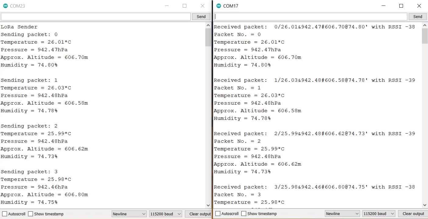
Results


8 Comments
We can encrypt data, but I could not understand how to make receiver to listen to only particular sender,
I have two transmitter Lora Module transmits some data, consider these as T1 and T2, and one receiver Lora modules R1.
Here receiver module R1 receives data from both transmitter T1 and T2,
So how can we make R1 to receive data from only T1?
Assign device address to identify from which receiver the data is being received.
Thanks for quick reply, i am new to this world, can you share document link?sample code?
It’s not working I connected same components in same circuit but it’s not working
Thanks, i did it at software level.
Hello, can i use this system with ra-01 lora?
can i use this system with lora ra – 01?
Y it’s not working