

Overview
In this project, we will learn how to use Reyax RYLR890 LoRa Module with Arduino. The RYLR890/RYLR896 transceiver module features the Lora long range modem that provides ultra-long range spread spectrum communication and high interference immunity whilst minimizing current consumption. Earlier we learned about LoRa Module LR1276/SX1276 & its interfacing with the STM32 Microcontroller through SPI Pins. Today we will learn about the UART LoRa Module that can be used with any microcontroller using only 4 pins.
The Lora Module RYLR890/RYLR896 communicates up to the range of 10-15Km. It is designed using the best noise reduction technology. The LoRa Module can be easily interfaced with Arduino Board, ESP8266, ESP32, or STM32 Microcontrollers. The power consumption of the module is very low about 43mA during transmission & 16.5mA during receiving. Putting the module to sleep mode further reduces the power to 0.5uA.
In this tutorial, we will first make a simple Arduino LoRa RYLR890 Transmitter/Receiver Circuit & do a point-to-point communication like controlling a LED brightness Wirelessly using Potentiometer. In the 2nd example, we will send the sensor data wirelessly from transmitter to receiver. The sensor we are going to use is the BME280 Sensor that can measure environmental temperature, humidity, pressure & altitude.
Bill of Materials
Following are the list of components required for making this simple LoRa Based projects. All the components can be easily assembled on a breadboard. The components purchase link from Amazon is given below.
| S.N. | Components Name | Quantity | Purchase Links |
|---|---|---|---|
| 1 | Arduino Nano Board | 2 | Amazon | AliExpress |
| 2 | LoRa Module RYLR890/RYLR896 | 2 | Amazon | AliExpress |
| 3 | Potentiometer 10K | 1 | Amazon | AliExpress |
| 4 | LED 5mm Any Color | 1 | Amazon | AliExpress |
| 5 | BME280 Sensor | 1 | Amazon | AliExpress |
| 6 | Resistor 4.7K | 1 | Amazon | AliExpress |
| 7 | Resistor 10K | 1 | Amazon | AliExpress |
| 8 | Connecting Wires | 10 | Amazon | AliExpress |
| 9 | Breadboard | 1 | Amazon | AliExpress |
Reyax LoRa RYLR890/RYLR896
The LoRa Module RYLR890/RYLR896 from Reyax Technologies is based on Semtech LoRa Chip SX1276 and STM32L151C8T6 microcontroller. The SX1276 Chips operates on frequency 868/915Mhz & is interfaced to STM32L151C8T6 via SPI Pins.

The Reyax RYLR890/RYLR896 LoRa module can be easily interfaced with Arduino using the UART Pins. There is a list of AT Commands that can be used to perform any task like sending the data or receiving the data or putting the device to sleep mode. You can learn more about the AT Commands from this Technical AT Command Documentation: RYLR890/RYLR896
Features & Specifications
1. Semtech SX1276 Chip
2. Excellent blocking immunity
3. Operating Voltage: 2.8V – 3.3V
4. Low Current Consumption (43mA in Transmission, 16.5 in receiving, 0.5uA in Sleep Mode)
5. Communication Range: 4.5km Typical & 15km Maximum
6. High RF sensitivity: -148dBm
7. Control easily by AT commands
8. 127 dB Dynamic Range RSSI
9. Small PCB integrated antenna
10. AES128 Data encryption
Pinouts
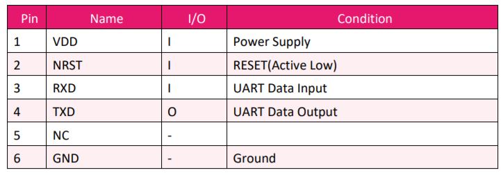
Interfacing RYLR890/RYLR896 LoRa Module with Arduino
Now let us learn how we can interface the RYLR890/RYLR896 LoRa Module with Arduino Board. In this first example we will make a transmitter and a receiver circuit & control the brightness of LED using the potentiometer Wirelessly.
Transmitter Circuit
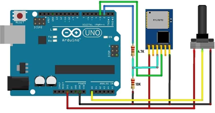
The transmitter circuit has the potentiometer connected to A0 Pin of Arduino to generate variable Analog voltage while rotating the potentiometer. The LoRa module operates at 3.3V so we need a voltage divider network for UART Pins as Arduino digital pins can generate 5V. So a 4.7K & 10K Resistor is used for a voltage divider network that converts 5V logic voltage to almost 3.4V. Assemble the circuit as shown in the image.
Receiver Circuit

The receiver circuit has the led connected to the D5 Pin of Arduino whose brightness can be adjusted while a signal from the transmitter is sent.
Source Code/Program
The code/program for the transmitter and receiver circuit is given below. You can upload the code to the both transmitter and receiver circuit after assembling them.
Transmitter Code
|
1 2 3 4 5 6 7 8 9 10 11 12 13 14 15 16 17 18 19 20 21 22 23 24 25 26 27 28 29 |
#include <SoftwareSerial.h> SoftwareSerial lora(2,3); int pot = A0; void setup() { // put your setup code here, to run once: Serial.begin(115200); lora.begin(115200); pinMode(pot, INPUT); } void loop() { int val = map(analogRead(pot),0,1024,0,255); Serial.println(val); String potval = String(val); String cmd = "AT+SEND=0,"+String(potval.length()) +","+ String(val)+"\r"; //Serial.println("AT+SEND=0,3,val"); lora.println(cmd); while(lora.available()){ Serial.write(lora.read()); } Serial.println(); Serial.println(cmd); delay(50); } |
Receiver Code
|
1 2 3 4 5 6 7 8 9 10 11 12 13 14 15 16 17 18 19 20 21 22 23 24 25 26 27 28 29 30 31 32 33 34 35 36 37 |
#include <SoftwareSerial.h> SoftwareSerial lora(2,3); int LED = 5; //String inString = ""; // string to hold input int val = 0; void setup() { // put your setup code here, to run once: Serial.begin(115200); lora.begin(115200); pinMode(LED, OUTPUT); } void loop() { //char ch; String inString; while (lora.available()) { if(lora.available()){ inString += String(char(lora.read())); } } if(inString.length()>0) { //Serial.println(inString); String potval; potval= inString.substring(9,12); Serial.println(potval); analogWrite(LED,potval.toInt()); } //delay(100); } |
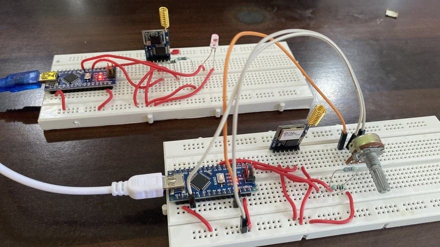
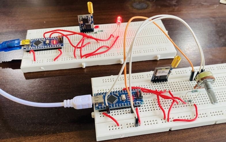
After the code is uploaded to both the microcontroller board, you can start testing the entire circuit. On the transmitter side, you need to rotate the potentiometer so that the receiver LED Brightness will increase or decrease.
Send Sensor Data wirelessly with LoRa RYLR890/RYLR896 & Arduino
In this 2nd example, we will send the BME280 Barometric Pressure Sensor Data wirelessly to LoRa Receiver. The BME280 Barometric Pressure Sensor measures Temperature, Pressure, Humidity & Altitude.
Transmitter Circuit
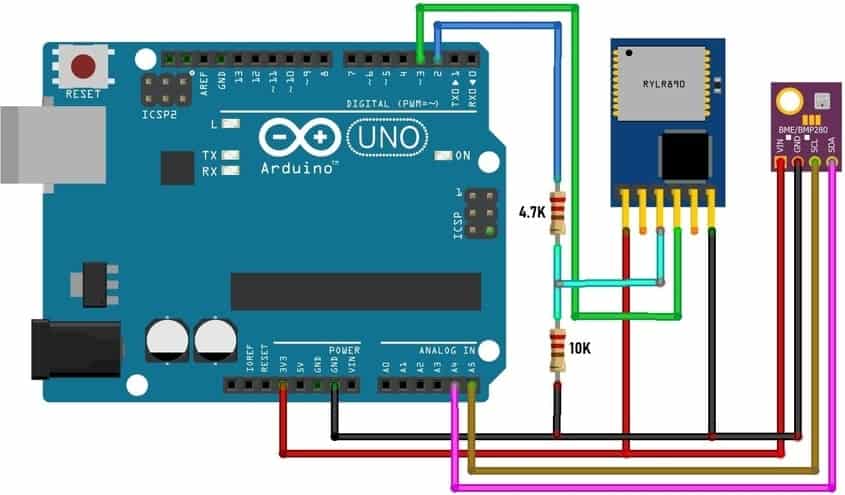
The transmitter circuit has the BME280 sensor connected to the I2C Pins of Arduino. The LoRa module operates at 3.3V so we need a voltage divider network for UART Pins as Arduino digital pins can generate 5V. So a 4.7K & 10K Resistor is used for a voltage divider network that converts 5V logic voltage to almost 3.4V. Assemble the circuit as shown in the image.
Receiver Circuit

The receiver circuit has nothing except the LoRa Module connected to the UART pin of the Arduino

Source Code/Program
The code/program for the transmitter and receiver circuit is given below. After assembling the entire circuit as per the circuit diagram, you can upload the code to the both transmitter and receiver circuit.
Transmitter Code
|
1 2 3 4 5 6 7 8 9 10 11 12 13 14 15 16 17 18 19 20 21 22 23 24 25 26 27 28 29 30 31 32 33 34 35 36 37 38 39 40 41 42 43 44 45 46 47 48 49 50 51 52 53 54 55 56 57 58 59 60 61 62 63 |
#include <SoftwareSerial.h> #include <Wire.h> #include <SPI.h> #include <Adafruit_Sensor.h> #include <Adafruit_BME280.h> SoftwareSerial lora(2,3); #define SEALEVELPRESSURE_HPA (1013.25) Adafruit_BME280 bme; void setup() { // put your setup code here, to run once: Serial.begin(115200); lora.begin(115200); if (!bme.begin(0x76)) { Serial.println("Could not find a valid BME280 sensor, check wiring!"); while (1); } } void loop() { float temperature = bme.readTemperature(); float pressure = bme.readPressure() / 100.0F; float altitude = bme.readAltitude(SEALEVELPRESSURE_HPA); float humidity = bme.readHumidity(); Serial.print(F("Temperature = ")); Serial.print(temperature); Serial.println(F("*C")); Serial.print(F("Pressure = ")); Serial.print(pressure); Serial.println(F("hPa")); Serial.print(F("Approx. Altitude = ")); Serial.print(altitude); Serial.println(F("m")); Serial.print(F("Humidity = ")); Serial.print(humidity); Serial.println(F("%")); String temp = String(temperature); String pres = String(pressure); String alt = String(altitude); String hum = String(humidity); String values = String(temp)+","+ String(pres)+","+ String(alt)+","+ String(hum); String cmd = "AT+SEND=0,"+String(values.length())+","+values; lora.println(cmd); while(lora.available()) { Serial.write(lora.read()); } Serial.println(); Serial.println(cmd); delay(5000); } |
Receiver Code
|
1 2 3 4 5 6 7 8 9 10 11 12 13 14 15 16 17 18 19 20 21 22 23 24 25 26 27 |
#include <SoftwareSerial.h> SoftwareSerial lora(2,3); void setup() { // put your setup code here, to run once: Serial.begin(115200); lora.begin(115200); } void loop() { String inString; while (lora.available()) { if(lora.available()){ inString += String(char(lora.read())); } } if(inString.length()>0) { Serial.println(inString); inString.remove(0); } } |
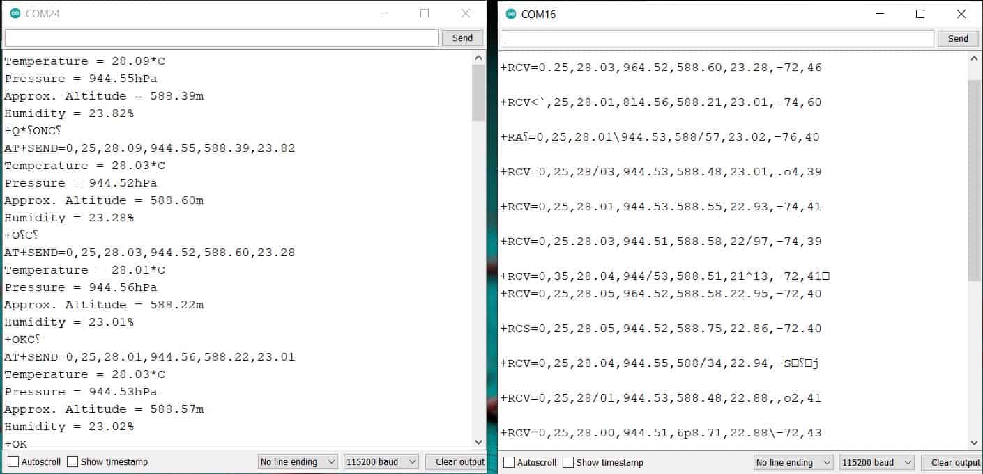
Once the code is uploaded, you can open the Serial Monitor for both the transmitter & receiver parts. The sender/transmitter circuit will read the BME280 Sensor data and send it wirelessly to the receiver. The receiver will receive the data and display it on Serial Monitor along with the RSSI signal.
So this is how we can make a point to point communication between Reyax LoRa RYLR890 or RYLR896 & Arduino.
Video Tutorial & Guide

Some other products from Reyax Technology like RYS8830 & RYB080I may be useful in some other wireless applications.

")


8 Comments
In your transmitter program, temp, pres, alt etc are declared as String. But in String values calculation, you have again say:
String values = String(temp)+”,”+ String(pres)+”,”+ String(alt)+”,”+ String(hum);
Probably should be the following ?
String values = temp+”,”+pres+”,”+alt+”,”+hum;
Hi I am connecting my lora module with esp32 and one module with arduino . can you let me know what directory i should use in both for transmitting and receiving ends of the modules .
Is the the schematic wrong for the reciever of the first example i only see 2 resistors in the picture?
The Schematic is correct. Those two resistors are 1k+1k valued resistors making it 2K. In the schematic, a 2k is directly mentioned.
Sorry, I am trying to make this project but is not working. Which two resistors 1k+1k you mean? the schematic shows a 10k, 4.7k and one resistor without the value. Can you clarify this please?
What is logic level output voltage of ESP32 (ESP32 ESP-WROOM-32 )? 5v or 3.3v?
I have to connect Lora module “REYAX RYLR998” to it, which works with 3.3v only.
I lost whole day but could not succeed in sending AT command using SoftwareSerial, I have ESP32 Dev Unit
SoftwareSerial lora(16, 17);
const int NETWORKID_LORA=5; //enter Lora Network ID
const int ADDRESS_LORA_NODE_GATEWAY=1;
lora.begin(115200); // default baud rate of module is 115200
delay(1000); // wait for LoRa module to be ready
lora.print((String)”AT+ADDRESS=” + ADDRESS_LORA_NODE_GATEWAY + “\r\n”);
delay(200);
lora.print((String)”AT+NETWORKID=” + NETWORKID_LORA + “\r\n”);
delay(200);
Please help
It doesn’t work.